
Create successful ePaper yourself
Turn your PDF publications into a flip-book with our unique Google optimized e-Paper software.
Bulletin 241-E Metric<br />
C E R T I F I E D E N I S O 9 0 0 1<br />
Mr. GoodTower ®
T H E A D V A N C E D T E C H N O L O G Y D ESIG N<br />
<br />
Since its founding in 1976,<br />
<strong>EVAPCO</strong>, Inc. has become a<br />
world-wide leader in supplying<br />
quality cooling equipment for<br />
thousands of customers in both the<br />
commercial and industrial markets.<br />
<strong>EVAPCO</strong>’s success has been the result of<br />
a continual commitment to product<br />
improvement, quality workmanship and<br />
a dedication to providing unparalleled<br />
service.<br />
Low Sound Solutions<br />
The New ESWA is available with<br />
Low Sound Solutions to reduce the<br />
overall sound generated from the<br />
top of the already quiet ESWA<br />
Closed Circuit Cooler. Each option<br />
provides various levels of sound<br />
reduction and can be combined to<br />
provide the lowest sound level<br />
available on a closed circuit cooler.<br />
Low Sound Options available<br />
Refer to page 11 for details<br />
Efficient Drift Eliminators<br />
• Advanced design removes mist from<br />
leaving airstream.<br />
• Corrosion resistant PVC for long life.<br />
†<br />
CTI Certified<br />
Refer to page 15<br />
for details<br />
Our emphasis on research and<br />
development has led to many product<br />
innovations – a hallmark of <strong>EVAPCO</strong><br />
through the years.<br />
The ongoing R & D Program enables<br />
<strong>EVAPCO</strong> to provide the most advanced<br />
products in the industry – technology<br />
for the future, available today.<br />
PVC Spray Distribution<br />
Header with ABS Nozzles<br />
• Nozzles are threaded to<br />
assure proper orientation.<br />
• Large orifice nozzles<br />
prevent clogging.<br />
• Threaded end caps for<br />
ease of cleaning.<br />
Totally Enclosed Pump Motors<br />
• Helps assure long, trouble-free operation.<br />
Z-725 Heavy Gauge Mill-Dip<br />
Galvanized Steel Construction<br />
See page 4 for additional informations<br />
(Stainless steel available as an affordable option)<br />
With 17 facilities in eight countries and<br />
over 170 sales offices in 42 countries<br />
world-wide, <strong>EVAPCO</strong> is ready to assist in<br />
all your equipment needs.<br />
Certificate of Compliance<br />
AT, USS, UAT, UT Cooling Towers<br />
ATW(B) and ESWA Closed Circuit Coolers<br />
ATC-E and HTC Evaporative Condensers<br />
Are certified to meet or exceed the Seismic and Wind Load Provisions<br />
set forth in the applicable building codes for this project.<br />
These products have been manufactured following all<br />
applicable quality assurance programs.<br />
Applicable Building Codes:<br />
Referenced Report:<br />
IBC 2006<br />
VMA-43387<br />
ASCE-7<br />
NFPA 5000<br />
Approval Agency:<br />
VMC Seismic Consulting Group<br />
<strong>EVAPCO</strong>...Specialists in Heat Transfer Products and Services. ID IBC COC 001<br />
IBC Compliant<br />
Design<br />
Refer to page 13<br />
for details<br />
† Mark owned by the Cooling Technology Institute<br />
2
P R O V I D I N G E A S I E R S O L U T I O N S A N D B E T T E R C H O I C E S<br />
<br />
WST Air Inlet Louvers<br />
(Water and Sight Tight)<br />
• Easily removable for access.<br />
• Designed to keep sunlight outpreventing<br />
biological growth.<br />
• Keeps water in while keeping dirt<br />
and debris out.<br />
DESIGN AND CONSTRUCTION FEATURES<br />
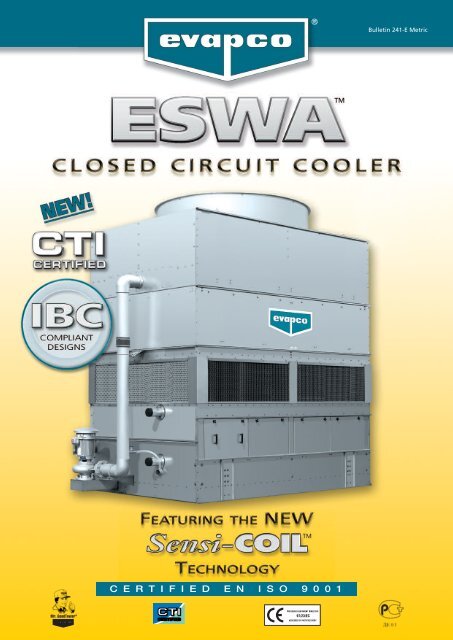
The new ESWA closed circuit cooler is another exciting product from <strong>EVAPCO</strong>. The ESWA is a new high performance<br />
version of the original ESW with greater capacity, more models and increased energy savings! The new ESWA is able to<br />
provide higher performance as a result of our new Sensi-Coil Technology, a new coil design that provides significant<br />
performance improvements on every ESWA model.<br />
Sensi-Coil Technology features over 20% more Thermal-Pak ® elliptical tubes packed densely together into the same coil<br />
plan area as the original ESW. This design also has 50% more water loading than the previous ESW line. More surface<br />
area plus more water equals higher capacity resulting in more performance with the ESWA in a smaller footprint with<br />
less energy.<br />
TM<br />
New<br />
Technology<br />
The NEW Sensi-Coil , exclusive on the new ESWA closed circuit cooler, features the<br />
maximum amount of Thermal-Pak elliptical tubes packed densely together in a new<br />
coil arrangement.<br />
The new Sensi-Coil transfers heat through its tube walls<br />
in a sensible exchange - No air travels through the tube<br />
bundle, therefore tighter tube spacing is possible. Look at<br />
the side by side tube spacing comparison below.<br />
Sensi-Coil <br />
Sensi-Coil <br />
Original Thermal-Pak Coil<br />
used in the ESW<br />
The Sensi-Coil Features:<br />
• More Thermal-Pak ® elliptical tubes densely packed together<br />
into the same plan area used on the original ESW.<br />
• Over 20% more coil surface area than the original ESW coil.<br />
• Higher water loading capability for more heat rejection,<br />
increasing from 8 l/s per m 2 to 12 l/s per m 2 , a 50% increase!<br />
• More surface area and more water equals higher capacity<br />
and increased energy efficiency.<br />
This innovative tight tube spacing is designed specifically to<br />
maximize sensible heat transfer, and is exclusive on the<br />
ESWA product line.<br />
Most Accessible<br />
Basin and Coil<br />
• Side access.<br />
• Large open area simplifies<br />
maintenance.<br />
• Basin may be inspected with<br />
pumps running.<br />
3<br />
DESIGN MAINTENANCE OPTIONS SOUND I B C C T I ENGINEERING SPECIFICATIONS
C L O S E D C I R C U I T C O O L E R<br />
Cool Dry<br />
Entering<br />
Air<br />
Hot Saturated Discharge Air<br />
Principle of Operation<br />
Cool Dry<br />
Entering<br />
Air<br />
Cooled<br />
Fluid Out<br />
Hot<br />
Fluid In<br />
Principle of Operation<br />
The warm process fluid circulates from the heat source to the<br />
coil of the closed circuit cooler. The fluid in the coil transfers<br />
its heat through the coil tube walls in a sensible exchange to<br />
the spray water that floods over the tubes. Having gained<br />
heat from the coil, the spray water then falls to the sump<br />
where it is circulated by the spray pump up through<br />
distribution piping to the spray nozzles. The warmed spray<br />
water is then distributed as a thin film over the fill section<br />
surface for maximum cooling efficiency. The fan system<br />
operates simultaneously, moving large volumes of air<br />
through the unit in a direction opposite the falling water.<br />
The air and water contact directly across the fill surface<br />
whereupon a small portion of the spray water is evaporated.<br />
The evaporation process provides a latent exchange of heat<br />
from the spray water to the air passing through the unit.<br />
The air is then discharged from the unit as a warm and<br />
saturated stream with a final dissipation of heat to the<br />
atmosphere. The spray water exits the fill section as a cooled<br />
fluid where it floods across the coil in a repeat cycle.<br />
New Sensi-Coil Technology<br />
The NEW Sensi-Coil , exclusive on the new ESWA closed<br />
circuit cooler, features the maximum amount of Thermal-<br />
Pak elliptical tubes packed densely together in a new coil<br />
arrangement designed with over 20% more surface area.<br />
stacked within the unit’s<br />
protective casing. The<br />
structural strength of the<br />
assembled fill pack enables it<br />
to be used as a working<br />
platform.<br />
EVAPAK ® fill is impervious to<br />
rot and decay. *U.S. Patent #5,124,087<br />
<strong>EVAPCO</strong>AT Corrosion Protection System<br />
Sensi-Coil <br />
Evapco's coils are manufactured within the most stringent<br />
of quality control procedures. Each circuit consists of high<br />
quality steel tubing formed into a continuous serpentine<br />
circuit. Each circuit is then inspected and tested prior to<br />
being welded into a framed coil assembly. Finally, the<br />
assembled coil is air pressure tested under water in<br />
accordance with the “Pressure Equipment Directive” (PED)<br />
97/23/EC. The entire coil assembly is then hot-dip<br />
galvanized for industrial strength corrosion protection.<br />
The Z-725 Mill Hot-Dip Galvanized Steel Construction is<br />
the heaviest level of galvanizing available for<br />
manufacturing closed circuit coolers and has more zinc<br />
protection than competitive designs using Z-275 and<br />
Z-600 steel.<br />
Z-725<br />
Z-600<br />
ZINC<br />
STEEL<br />
ZINC<br />
<strong>EVAPCO</strong><br />
OTHERS<br />
DESIGN<br />
4<br />
Note: Closed circuit coolers should only be used on sealed,<br />
pressurized systems. Continual aeration of the water in an open<br />
system can cause corrosion inside the tubes of the cooler leading<br />
to premature failure.<br />
Patented ® EVAPAK Fill*<br />
The patented EVAPAK ® fill is specially designed to induce<br />
highly turbulent mixing of the air and water for superior<br />
heat transfer. The fill section is constructed of polyvinyl<br />
chloride (PVC) sheets which are thermally formed into a<br />
cross flute design. The individual fill sheets are bonded<br />
together to form rigid fill blocks. The fill blocks are then<br />
Z-275<br />
There are various grades of mill galvanized steel each<br />
with differing amounts of zinc protection. <strong>EVAPCO</strong> has<br />
been a leader in the industry in developing heavier<br />
galvanizing, and was the first to standardize on Z-725 mill<br />
hot-dip galvanized steel. Z-725 designation means there is<br />
a minimum of 725 g/m 2 of surface area as measured in a<br />
triple spot test. During fabrication, all panel edges are<br />
coated with a 95% pure zinc-rich compound for extended<br />
corrosion resistance.
E N E R G Y E F F I C I E N T L O W S O U N D<br />
The new Evapco ESWA represents another leap forward<br />
in coil technology. Evapco has taken the already energy<br />
efficient, low sound, ESW and made it even more efficient<br />
and added additional capacity through the new Sensi-<br />
Coil Technology Design. The ESWA is yet another<br />
example of Evapco's continuous commitment to<br />
developing innovative products which surpass industry<br />
standards and expectations.<br />
Low Energy As Standard<br />
The New ESWA again stands apart as being the most<br />
energy efficient closed circuit cooler ever. This efficiency,<br />
in terms of lower fan horsepower, translates directly to<br />
lower operating costs…significantly lower operating<br />
costs. With the ESWA installed, customers can realize<br />
immediate energy savings which continue each and every<br />
year for the life of the equipment.<br />
• Replace inefficient units:<br />
The potential for energy savings alone is often enough<br />
to justify replacing inefficient fluid coolers with high<br />
efficiency models. As an example, a 250 ton centrifugal<br />
fan fluid cooler with 44 kW worth of fan motors can be<br />
replaced by an ESWA model with a fan motor size of<br />
only 11 kW. This tremendous reduction in fan motor<br />
size offers annual savings of 10.400 € per year based on<br />
3.500 hours of operation and an electric rate of<br />
0,09 €/kWh.<br />
• New Product Comparison:<br />
When comparing the cost of new equipment, energy<br />
efficiency and consumption are important factors for<br />
determining the total product cost. Units having a<br />
lower first cost but higher energy requirements are<br />
more expensive to operate and normally end up costing<br />
the customer more over the life of the equipment.<br />
Annual Savings €<br />
4 to 11 kW Reduction<br />
8,000<br />
7,000<br />
11 kW Reduction<br />
6,000<br />
5,000<br />
7.5 kW Reduction<br />
4,000<br />
3,000<br />
4 kW Reduction<br />
2,000<br />
1,000<br />
0<br />
1500 2500 3500 4500 5500 6500 7500 8500<br />
Hours of Operation<br />
Low Sound As Standard<br />
In addition to being the most energy efficient, the ESWA is<br />
also the quietest axial fan fluid cooler. The removable access<br />
panels around the base of the unit block water noise to the<br />
point where casual conversation is possible at only five feet<br />
from the unit…even with the fan running on high speed.<br />
And at a distance of five feet above the fan, the ESWA has<br />
sound levels that are up to 13dBA less than other axial fan<br />
fluid coolers of equal capacity.<br />
Research and Development<br />
Evapco's research and development team considered the<br />
basic principles of heat transfer to develop the patented<br />
Optimized Technology that was used in the ESW closed<br />
circuit cooler. Optimized Technology combines “latent”<br />
heat transfer over the fill and “sensible” heat transfer<br />
over the coil to maximum heat transfer while minimizing<br />
scale buildup on the coil.<br />
The new ESWA closed circuit cooler was developed to<br />
take Optimized Technology to the next level. The ESWA<br />
features more capacity than ever before, 12-24% more on<br />
average. This is done by using Evapco's new higherdensity<br />
Sensi-Coil Technology. By using this new coil<br />
design (patent pending), and higher water loadings over<br />
the coil, Evapco has achieved significant performance<br />
gains. This means more performance, a smaller footprint,<br />
and less energy.<br />
Patented Optimized Technology*<br />
Evapco is the first manufacturer to develop a closed circuit<br />
cooler with Patented Optimized Technology ® . The<br />
performance of the fill section in the original ESW was<br />
optimized with counterflow heat transfer and a flow rate<br />
of 4 l/s per square meter. The new ESWA is now optimized<br />
at 6 l/s per square meter for increased cooling through the<br />
fill section.<br />
After leaving the fill section, the water focuses on the coil<br />
at a rate of approximately 12 l/s per square meter,<br />
depending on the boxsize – this continues to be the<br />
highest flow over a coil in the industry! This is an increase<br />
of 4 l/s per square meter from the original ESW. Now at<br />
12 l/s per square meter, more heat is being stripped from<br />
the coil by sensible heat transfer.<br />
Annual Savings €<br />
40,000<br />
30,000<br />
20,000<br />
10,000<br />
19 to 49 kW Reduction<br />
49 kW Reduction<br />
33 kW Reduction<br />
26 kW Reduction<br />
19 kW Reduction<br />
Other benefits of this unique counterflow design:<br />
• The coil is easily piped at ground level.<br />
• The coil is easily inspected and accessible at ground<br />
level via removable cover panels around the unit.<br />
• Discharge hood with dampers are not required...the<br />
sheltered enclosure around the coil reduces heat loss<br />
and eliminates natural drafts across the coil.<br />
0<br />
1500 2500 3500 4500 5500 6500 7500 8500<br />
Hours of Operation<br />
Annual savings based on fan motor efficiency = 0.924<br />
and energy cost of 0,09 €/kWh<br />
*U.S. Patent #6,598,862<br />
5<br />
DESIGN
D E S I G N<br />
B E N E F I T S<br />
Spray Water Temperature<br />
16°C<br />
13°C<br />
11°C<br />
8°C<br />
Entering Air at -12°C Wet-Bulb Temperature<br />
Sunlight<br />
Air Intake<br />
Splashout<br />
Debris<br />
Counterflow... Optimum Design for<br />
Freezing Climates<br />
The counterflow design of the New ESWA Closed Circuit<br />
Cooler is well suited for winter operation. The fill section is<br />
totally encased, and protected from freezing winds thus<br />
inhibiting ice formation on the fill section. The even<br />
temperature gradient of the counterflow design further<br />
improves winter operability by eliminating cold spots.<br />
Evapco's counterflow design solves the problem of fill<br />
collapse due to ice formation. This is a problem of<br />
crossflow designs.<br />
Water Sight Tight Air Inlet Louver*<br />
Evapco's innovative air inlet louvers are both water and<br />
sight tight to ensure that the water stays in and the<br />
sunlight stays out of the cold water basin. Using extensive<br />
computational fluid dynamics modeling, Evapco engineers<br />
developed a louver to improve “splash resistance” while<br />
maximizing airflow. The resulting design maximizes<br />
thermal performance while minimizing water loss. This<br />
sight tight design also inhibits algae growth more<br />
effectively than previous designs.<br />
Evapco’s louver design solves the problem of the<br />
circulating water and heat transfer surfaces being directly<br />
exposed to external contaminants and the harsh<br />
surroundings.<br />
DESIGN<br />
6<br />
Water Distribution System<br />
The water distribution system is enclosed and completely<br />
protected by the casing panels and drift eliminators. The<br />
eliminators also function as effective debris screens which<br />
block sunlight and prevent debris from entering the spray<br />
system.<br />
The water distribution system is made with non-corrosive<br />
materials including schedule 40 PVC pipe and durable ABS<br />
plastic water diffusers.<br />
The spray branch piping is easily removed and designed<br />
with threaded end-caps for easy cleaning. The water<br />
diffusers have wide openings with anti-sludge rings to<br />
prevent clogging from sediment and debris.<br />
Evapco’s design avoids the problems of biological growth<br />
and clogging that can occur due to a water distribution<br />
system that is open with direct exposure to the<br />
surroundings.<br />
Efficient Drift Eliminators**<br />
The New ESWA is provided with an efficient drift<br />
eliminator system that effectively reduces entrained water<br />
droplets from the air discharge to less than 0.001% of the<br />
spray water flow rate.<br />
The eliminators are constructed of non-corrosive PVC with<br />
a multi-pass design for maximum drift reduction. They are<br />
assembled in modular sections for easy removal and access<br />
to the water distribution system.<br />
In addition to reducing drift, the eliminators also function<br />
as effective debris screens which protect the spray system<br />
from sunlight and debris.<br />
*U.S. Patent #6,923,250<br />
**U.S. Patent #6,315,804
M A I N T E N A N C E<br />
A D V A N T A G E S<br />
The Advanced Technology Easy Maintenance Basin Design<br />
The cold water basin is perhaps the most important area for maintenance in an evaporative cooler. Service mechanics<br />
who work on this equipment know that dirt, debris and silt all settle out in the basin. Because basin maintenance is<br />
important and should be performed regularly, Evapco designed the basin to make inspection, cleaning and flushing as<br />
easy as possible.<br />
<strong>EVAPCO</strong>’s basin is designed for quick and easy access with the following valuable features:<br />
Easy Access<br />
The cold water basin section is easily accessible from<br />
ground level. The basin is provided with solid access<br />
panels which are designed to protect the basin water<br />
and heat transfer coil from direct exposure to sunlight<br />
and debris. The access panels are light-weight and easy<br />
to remove. With the access panels removed, a service<br />
mechanic has complete access to the basin floor, heat<br />
transfer coil, float assembly and pump strainer.<br />
Clean Pan Basin Design<br />
The basin of the New ESWA is sloped toward a<br />
depressed area where the drain is located. With the<br />
"Clean Pan" design, it is easy for a service mechanic to<br />
flush the pan without getting wet feet. Other fluid<br />
cooler designs may necessitate getting inside of the<br />
unit for complete cleaning.<br />
Stainless Steel Strainers<br />
The <strong>EVAPCO</strong> standard for many years, the stainless steel<br />
strainer is one component that is subject to excessive<br />
wear and corrosion. With stainless steel construction,<br />
this component will last the life of the unit.<br />
MAINTENANCE<br />
7
M A I N T E N A N C E<br />
A D V A N T A G E S<br />
The Advanced Technology Easy Maintenance Drive System<br />
The <strong>EVAPCO</strong> POWER-BAND drive system utilized on the New ESWA Closed Circuit Cooler is the easiest belt drive system<br />
to maintain in the industry. Unlike other designs, there is no need to enter the cold water basin to climb up the plenum<br />
for access to motors, bearings or belts. All routine and periodic maintenance on the drive system can be safely<br />
performed from the exterior of the unit. The most significant benefits and features of Evapco’s drive system are<br />
detailed below.<br />
Models with Motors Mounted Externally<br />
Models ESWA-72, 96 and 142<br />
The fan motor and drive assembly are designed for easy service and<br />
adjustment from the unit’s exterior. The Totally Enclosed fan motor is<br />
mounted external to the unit with a protective cover which swings aside<br />
for maintenance. A large access door adjacent to the fan motor swings<br />
open enabling easy access to the fan drive system. The belt tension can<br />
be checked and adjusted easily from the outside of the unit. The fan<br />
shaft bearings also have their lubrication lines extended to the access<br />
door for added convenience.<br />
Models with Swing-Out Motors<br />
Models ESWA-144 and 216<br />
The fan motor is Totally Enclosed, Air Over (TEAO) and specifically designed for evaporative cooling applications. The<br />
motor is mounted inside of the unit on an adjustable base that enables the motor to swing outside the unit for easy<br />
access. The belt tension is easily checked and adjusted from outside the access door. Evapco provides a special tool for<br />
belt adjustment which also functions as a locking mechanism for the motor base adjustment. Lubrication lines for the fan<br />
shaft bearings are also extended to the access door for added convenience.<br />
Internally mounted<br />
fan motor can swing<br />
outside the unit for<br />
easy access.<br />
Internal motor...<br />
...with swing-out base<br />
MAINTENANCE<br />
“With all periodic and routine maintenance for the drive system performed from the side<br />
of the unit, Evapco drive systems are the most serviceable in the industry.”<br />
8
D R I V E<br />
S Y S T E M<br />
The Advanced Technology POWER-BAND Drive System Design<br />
The New ESWA Closed Circuit Cooler features the highly successful POWER-BAND Belt Drive System. The POWER-BAND<br />
Drive System has performed consistently with trouble-free operation in the most severe conditions of closed circuit<br />
cooler applications.<br />
POWER-BAND Drive System Includes:<br />
• Solid back POWER-BAND drive belt<br />
• Totally enclosed fan motors<br />
• Aluminum sheaves<br />
• Fan shaft bearings with minimum 75,000 hrs. L-10 life<br />
POWER-BAND Belt<br />
POWER-BAND Belt Drive<br />
The POWER-BAND drive is a solid-backed multigroove<br />
belt designed for closed circuit cooler service. The drive<br />
belt is sized for 150 percent of the motor nameplate<br />
kW and constructed of neoprene with polyester chords.<br />
Band belts are field-proven with 20 years of successful<br />
operation.<br />
Drive System Sheaves<br />
Drive system sheaves are constructed of an aluminum<br />
alloy for corrosion resistance in the humid closed circuit<br />
cooler environment.<br />
TEFC Fan Motor<br />
Fan Shaft Bearings<br />
The fan shaft bearings on the ESWA closed circuit<br />
cooler are specially selected to provide long life,<br />
minimizing costly downtime. They are rated for an L- 10<br />
life of 75,000 to 135,000 hours, making them the<br />
heaviest duty pillow block bearings in the industry.<br />
TEAO Fan Motor<br />
Fan Motors<br />
All ESWA Closed Circuit Coolers utilize Totally Enclosed<br />
fan motors (T.E.F.C. or T.E.A.O.) designed specifically for<br />
evaporative cooling application. In addition to the<br />
standard efficiency motors, the following motor options<br />
are available:<br />
• Premium efficiency motors<br />
• Two speed single winding<br />
• Two speed two winding<br />
• Mill and chemical duty<br />
• Inverter-duty motors for VFD applications<br />
• Explosion proof<br />
MAINTENANCE<br />
9
O P T I O N A L<br />
E Q U I P M E N T<br />
External Platforms & Motor Davits<br />
Electric Heaters<br />
Electric immersion heaters are available to protect the<br />
basin water from freezing. Basin heaters are sized to<br />
maintain a 4,5°C pan water temperature at -18°C<br />
ambient with the fans off*. The heater option includes a<br />
thermostat and low water protection device to control<br />
the heater and to prevent it from energizing unless they<br />
are completely submerged.<br />
Additional heater options are also available including<br />
contactors, transformers and disconnects.<br />
* Electric heater selection based on -18°C ambient temperature.<br />
Lower design ambient heaters are available in accordance with<br />
Table 3 on page 17.<br />
OPTIONS<br />
External platforms provide a sturdy base for access to the<br />
drive components, water distribution and drift<br />
eliminators. The platform mounts easily to the unit and<br />
requires no external support. The platform option<br />
includes a vertical aluminum ladder. A safety cage for<br />
the ladder is also available if required for the installation.<br />
Motor<br />
davit<br />
The motor davit option is an economical option which<br />
eliminates the need for a crane in the event that a fan<br />
motor has to be removed. The service mechanic needs<br />
only to have a chain-fall or come-along for easy removal<br />
of these heavy items. The motor davit is constructed from<br />
heavy duty galvanized steel with easy mounting to the<br />
unit in the field.<br />
Electric Water Level Control<br />
An electric water level control package is available as an<br />
alternative to the standard mechanical makeup valve and<br />
float ball. This package provides accurate control for the<br />
basin water level and does not require field adjustment,<br />
even under varying operating conditions.<br />
The control was designed by <strong>EVAPCO</strong> and is<br />
manufactured exclusively for <strong>EVAPCO</strong>. It consists of<br />
multiple heavy duty stainless steel electrodes.<br />
These electrodes are mounted external to the unit in a<br />
vertical stand pipe. For winter operation, the stand pipe<br />
must be wrapped with electric heating cable and<br />
insulated to<br />
protect it from<br />
freezing. The<br />
solenoid valve(s)<br />
for the makeup<br />
water connection<br />
is factory supplied<br />
and is ready for piping to<br />
a water supply with a<br />
pressure between 172 and<br />
345 kPa.<br />
Other Options<br />
• Heater Control Packages<br />
• Vibration Isolators<br />
• Vibration Switches<br />
• Remote Sump Connections<br />
• Motors–Energy Efficient / Inverter Duty<br />
2 speed / 1winding and<br />
2 speed / 2 windings<br />
• Sloped Ladders<br />
10
Ultra Quiet<br />
Closed Circuit<br />
Cooler<br />
The ESWA Closed Circuit<br />
Cooler is now available<br />
with two (2) equipment<br />
options to reduce the<br />
overall sound<br />
generated from<br />
the side or top<br />
of the ESWA<br />
Closed Cicuit<br />
Cooler. Each<br />
option provides<br />
various levels of<br />
sound reduction<br />
and can be used in<br />
combination to<br />
provide the lowest sound level.<br />
Ultra Quiet operation<br />
for induced draft<br />
counterflow<br />
Closed Circuit Coolers<br />
SOUND<br />
11
A D V A N C E D<br />
Super Low Sound Solution for Sound Sensitive Applications<br />
T E C H N O L O G Y<br />
L O W S O U N D S O L U T I O N S<br />
Family of Super Low Sound Fans<br />
Improved Sound Quality versus Standard Fan<br />
The Super Low Sound Fan<br />
Reduced Sound Levels versus<br />
Model ESWA Standard Fan<br />
<strong>EVAPCO</strong>'s Super Low Sound Fan on the ESWA<br />
closed circuit cooler utilizes an extremely wide chord<br />
blade design applied for sound sensitive<br />
applications where the lowest sound levels are<br />
desired. The fan is one piece molded heavy duty FRP<br />
construction utilizing a forward swept blade design.<br />
The Super Low Sound Fan reduces sound levels 9 to<br />
15 dB(A) compared to standard fans.<br />
Blade Passing Frequencies<br />
The SUPER Low Sound Fan on the ESWA closed circuit cooler<br />
reduces sound levels 9-15 dB(A) and eliminates audible blade<br />
passing frequencies indicative of straight bladed axial type fans.<br />
Refer to the Narrow Band Spectrum graph which shows how<br />
straight bladed axial fans produce blade passing frequencies –<br />
the same phenomena that produce the signature pulsating<br />
helicopter noise.<br />
The blade passing frequencies are audible spikes in sound<br />
pressure levels, but are not apparent in the octave band<br />
sound spectrum.<br />
Sound Pressure Level (dB)<br />
Standard Axial Fan<br />
Super Low Sound Fan<br />
Frequency (Hz)<br />
Narrow Band Spectrum Analysis<br />
SOUND<br />
The Super Low Sound Fan on the ESWA Closed Circuit Cooler reduces sound levels and betters the sound quality!<br />
Additional Solutions for Sound Sensitive Applications<br />
Low Sound Fan 4 – 7 dB(A) Reduction!<br />
The Low Sound Fan offered by <strong>EVAPCO</strong> is a wide chord blade design for<br />
sound sensitive applications where low sound levels are desired. The Low<br />
Sound Fan shall utilize a unique soft-connect blade-to-hub design that is<br />
compatible with Variable Speed Drives.<br />
The Low Sound Fan is capable of reducing the unit sound pressure levels<br />
4 dB(A) to 7 dB(A), depending upon specific unit selection and<br />
measurement location. The fans are high efficiency axial propeller type<br />
and are on the ESWA Closed Circuit Coolers.<br />
The Low Sound Fan is available on all 2.4 m wide and larger ESWA Closed<br />
Circuit Coolers.<br />
NOTE: These low sound options may impact the overall installed dimensions of the ESWA<br />
Closed Circuit Cooler selected.<br />
Consult <strong>EVAPCO</strong>’s iES selection software for unit sound levels. If a detailed analysis or full<br />
octave band data sheet is required for your application, please consult your <strong>EVAPCO</strong> Sales<br />
Representative.<br />
12
We Stand Tall<br />
Through it All!<br />
The International<br />
Building Code (IBC) is a<br />
comprehensive set of<br />
regulations addressing<br />
the structural design<br />
and installation<br />
requirements for<br />
building systems–<br />
including HVAC<br />
and industrial<br />
refrigeration<br />
equipment.<br />
I B C<br />
With the advent<br />
of the IBC,<br />
<strong>EVAPCO</strong> is<br />
proud to<br />
introduce the new and<br />
improved line of ESWA Closed<br />
Circuit Coolers with IBC 2006<br />
compliance standard.<br />
Wind, Rain,<br />
Earthquake<br />
and Hurricane<br />
<strong>EVAPCO</strong> Closed Circuit Coolers… designed to<br />
withstand seismic or wind load forces.<br />
13
I B C C O M P L I A N C E<br />
In its continuing commitment to be the leaders in evaporative cooling equipment<br />
design and services, <strong>EVAPCO</strong> ESWA Closed Circuit Coolers are now Independently Certified to<br />
withstand Seismic and Wind Loads in accordance with IBC 2006.<br />
I B C<br />
What is IBC<br />
International Building Code<br />
The International Building Code (IBC) is a comprehensive set of<br />
regulations addressing both the structural design and the<br />
installation requirements for building systems – including HVAC<br />
and industrial refrigeration equipment.<br />
Compared to previous building codes that considered only the<br />
building structure and component anchorage, the requirements<br />
contained within the IBC address anchorage, structural integrity,<br />
and the operational capability of a component following either a<br />
seismic or wind load event. Simply stated, the IBC code<br />
provisions require that evaporative cooling equipment, and all<br />
other components permanently installed on a structure, must be<br />
designed to meet the same seismic or wind load forces as the<br />
building to which they are attached.<br />
How Does IBC 2006 Apply to Closed Circuit Cooler<br />
Based on site design factors, calculations are made to determine<br />
the equivalent seismic “g force” and wind load (kilo-Newton per<br />
square meter, kN/m 2 ) on the unit. The cooling tower must be<br />
designed to withstand the greater of either the seismic or wind<br />
load.<br />
All locations with design criteria resulting in a seismic design<br />
force of up to 1.0g or a wind load of 2,87 kN/m 2 or below will<br />
be provided with the standard ESWA structural design. An<br />
upgraded structural design is available for installations with<br />
design criteria resulting in “g forces” greater than 1.0g. The<br />
highest “g force” location in North America is 5.12g. The<br />
highest wind load shown on the maps is 273 km/h, which is<br />
approximately equal to 6,94 kN/m 2 velocity pressure. Therefore,<br />
the upgraded structural design package option for the New<br />
ESWA is designed for 5.12 g and 6,94 kN/m 2 making it<br />
applicable to most building locations all over the World.<br />
Design Implementation<br />
<strong>EVAPCO</strong> applies the seismic design and wind load information<br />
provided for the project to determine the equipment design<br />
necessary to meet IBC requirements. This process ensures that the<br />
mechanical equipment and its components are compliant per the<br />
provisions of the IBC as given in the plans and specifications for<br />
the project.<br />
Independent Certification<br />
Although the IBC references and is based on the structural<br />
building code ASCE 7, many chapters and paragraphs of ASCE 7<br />
are superceded by the IBC, independent certification and<br />
methods of analysis are such paragraphs. Per the most recent<br />
edition of the code, the <strong>EVAPCO</strong> compliance process included an<br />
exhaustive analysis by an independent approval agency. As<br />
required by the International Building Code, <strong>EVAPCO</strong> supplies a<br />
certificate of compliance as part of its submittal documents. The<br />
certificate of compliance demonstrates that the equipment has<br />
been independently tested and analyzed in accordance with the<br />
IBC seismic and wind load requirements. Evapco has worked<br />
closely with the independent approval agency, The VMC Group,<br />
to complete the independent equipment testing and analysis.<br />
If the seismic “g force” or wind load requirements for the project<br />
site are known, <strong>EVAPCO</strong>’s online equipment selection software,<br />
iES, will allow you to choose the required structural design<br />
package – either standard construction or upgraded<br />
construction.<br />
For further questions regarding IBC compliance, please contact<br />
your local <strong>EVAPCO</strong> Representative.<br />
Certificate of Compliance<br />
AT, USS, UAT, UT Cooling Towers<br />
ATW(B) and ESWA Closed Circuit Coolers<br />
ATC-E and HTC Evaporative Condensers<br />
Are certified to meet or exceed the Seismic and Wind Load Provisions<br />
set forth in the applicable building codes for this project.<br />
These products have been manufactured following all<br />
applicable quality assurance programs.<br />
Applicable Building Codes:<br />
IBC 2006<br />
ASCE-7<br />
NFPA 5000<br />
Referenced Report:<br />
VMA-43387<br />
Approval Agency:<br />
VMC Seismic Consulting Group<br />
<strong>EVAPCO</strong>...Specialists in Heat Transfer Products and Services. ID IBC COC 001<br />
14
CTI Certified<br />
ESWA Closed<br />
Circuit Coolers<br />
CTI Certification<br />
Purpose (STD-201)<br />
C T I<br />
This standard sets forth<br />
a program whereby the<br />
Cooling Technology<br />
Institute will certify<br />
that all models of a<br />
line of evaporative<br />
heat rejection<br />
equipment offered<br />
for sale by a specific<br />
manufacturer will<br />
perform<br />
thermally in<br />
accordance with the<br />
manufacturer’s<br />
published ratings...<br />
CTI<br />
Validation Number<br />
06-13-05<br />
† Mark owned by the Cooling Technology Institute<br />
15
C T I C E R T I F I C A T I O N<br />
In its continuing commitment to be the leaders in evaporative cooling equipment design and<br />
services, <strong>EVAPCO</strong> ESWA Closed Circuit Coolers are now Independently Certified by CTI, to<br />
perform thermally in accordance with the published data.<br />
What is CTI<br />
C T I<br />
Cooling Technology Institute<br />
The Cooling Technology Institute is an organization<br />
headquartered in the United States with over 400 member<br />
companies from around the globe. CTI membership is composed<br />
of manufacturers, suppliers, owner operators, and test agencies<br />
from over 40 countries. In 2008 CTI certified more than 5000<br />
Evaporative Heat Transfer Systems (EHTS) from 49 product line of<br />
24 participants.<br />
COOLING TECHNOLOGY<br />
INSTITUTE<br />
Standard for Thermal Performance<br />
Certification<br />
of<br />
Evaporative Heat Rejection<br />
Equipment<br />
COOLING TECHNOLOGY<br />
CTI CODE TOWER<br />
Standard Specifications<br />
Acceptance Test Code for<br />
Closed Circuit Cooling Towers<br />
Part 1:<br />
Appendix A:<br />
Appendix B:<br />
INSTITUTE<br />
Procedure<br />
SI Example<br />
IP Example<br />
CTI’s Mission and Objectives<br />
This can be best explained by the CTI’s published Mission<br />
statement and Objectives revised in December 2003 and<br />
published on their website www.cti.org.<br />
STD 201<br />
Supplemen to CTI Code ATC-105(96)<br />
CTI Mission Statement<br />
To advocate and promote the use of environmentally<br />
responsible Evaporative Heat Transfer Systems (EHTS)<br />
for the benefit of the public by encouraging:<br />
• Education<br />
• Research<br />
• Standards Development and Verification<br />
• Government Relations<br />
• Technical Information Exchange<br />
CTI Objectives<br />
• Maintain and expand a broad base membership of<br />
individuals and organizations interested in<br />
Evaporative Heat Transfer Systems (EHTS).<br />
• Identify and address emerging and evolving issues<br />
concerning EHTS.<br />
• Encourage and support educational programs in<br />
various formats to enhance the capabilities and<br />
competence of the industry to realize the maximum<br />
benefit of EHTS.<br />
• Encourage and support cooperative research to<br />
improve EHTS technology and efficiency for the<br />
long-term benefit of the environment.<br />
• Assure acceptable minimum quality levels and<br />
performance of EHTS and their components by<br />
establishing standard specifications, guidelines, and<br />
certification programs.<br />
• Establish standard testing and performance analysis<br />
systems and procedures for EHTS.<br />
• Communicate with and influence governmental<br />
entities regarding the environmentally responsible<br />
technologies, benefits, and issues associated with<br />
EHTS.<br />
• Encourage and support forums and methods for<br />
exchanging technical information on EHTS.<br />
Benefits to the End User<br />
CTI defines an independent testing certification program<br />
that is specifiable, enforceable and available to all<br />
equipment manufacturer’s. End users that purchase CTI<br />
certified products are assured that those products will<br />
perform thermally as specified.<br />
Additionally CTI certification is the first step for the Green<br />
Building Concept in <strong>Europe</strong>:<br />
• LEED - Leadership in Energy and Environmental<br />
Design<br />
• Best Available Practice<br />
• Green Building Rating System<br />
Thermal Performance Guarantee<br />
In addition to the CTI Certification, Evapco unequivocally<br />
guarantees the Thermal Performance of ALL Evapco<br />
Equipment. Every unit order is confirmed with a submittal<br />
package that includes an Evapco Thermal Performance<br />
Guarantee Certificate.<br />
Guarantee of Thermal Performance<br />
<strong>EVAPCO</strong> ® unequivocally guarantees the thermal performance of its equipment as shown on the<br />
certified drawings, when the equipment is installed in accordance with good engineering practice. If<br />
after installation and start-up there is any question regarding thermal performance of the equipment,<br />
at the owner’s request <strong>EVAPCO</strong> will send its engineers to the jobsite to conduct a performance test.<br />
This test may be observed by the owner and the consulting engineer or by their authorized<br />
representatives. If the results of the evaluation show the equipment to be deficient, <strong>EVAPCO</strong> will<br />
make the necessary repairs or alterations to correct the deficiency at no cost to the owner. If the<br />
equipment is found to be performing in accordance with its certified drawing, the owner is expected<br />
to reimburse the company for its costs associated with this performance test.<br />
<strong>EVAPCO</strong>...Specialists in Heat Transfer Products and Services.<br />
AOS2636<br />
16
C T I C E R T I F I C A T I O N<br />
CTI Certification Program<br />
CTI Certification Process<br />
• Submit Application for Certification<br />
• CTI completes a technical review of the product<br />
line submitted<br />
• CTI performs an initial qualification test in a<br />
laboratory on a specified model number<br />
• CTI issues an Approval Letter with Validation<br />
Number if test is passed. Letter is also distributed<br />
to all members of CTI to inform everyone that a<br />
successfull certification has been completed.<br />
The Certification Validation Number assigned<br />
should be fixed to each tower sold and displayed in<br />
all catalogs and other literature<br />
• Product Line must undergo an Annual Reverification<br />
Test - Different model number is selected every year<br />
• More details can be found on the CTI website<br />
www.cti.org<br />
Evapco <strong>Europe</strong> CTI Certified ESWA Product Line<br />
ESWA Line of CTI Certified Closed Cicuit Coolers<br />
• CTI Certification Validation Number 06-13-05<br />
• Includes the use of optional remote sump<br />
• Includes optional Super Low Sound Fan (SLSF)<br />
and Low Sound Fan (LSF)<br />
• Includes high flow header connections and series<br />
flow coil configuration<br />
• Includes optional external service platform and<br />
ladders for access<br />
• iES Technical data sheet will state “CTI Certified<br />
Selection” if the selection falls within the CTI<br />
Certification Test Parameters<br />
• Unit will receive a CTI Certified Shield located near<br />
the nameplate<br />
• Certification applies only to units with water as<br />
process fluid<br />
C T I<br />
CTI Certification Test Parameters<br />
• Entering Wet Bulb temperature - 12.8°C to 32.2°C<br />
• Cooling Range - Minimum of 2.2°C<br />
• Cooling Approach - Minimum of 2.8°C<br />
• Process Fluid Temperature - Maximum of 51.7°C<br />
• Barometric Pressure - 91.4 to 105 kPa<br />
• More details can be found on the CTI website<br />
www.cti.org<br />
CTI Certification Limitations<br />
• Specific manufacturer’s product line name and<br />
model numbers<br />
• Applicable only to product lines and model numbers<br />
submitted<br />
• Multiple cell model numbers are allowed if the<br />
airflow is not affected or the configuration impact is<br />
included in the unit rating<br />
• Optional accessories are allowed if the aiflow is not<br />
affected or the accessory impact is accounted for in<br />
the rating<br />
• More details can be found on the CTI website<br />
www.cti.org<br />
Note<br />
All CTI Certified Product Lines of all manufacturers<br />
with CTI certified products can be found on the<br />
website: http://www.cti.org/certification.shtml<br />
† Mark owned by the Cooling Technology Institute<br />
17
18<br />
Notes:
Engineering<br />
Data<br />
ENGINEERING<br />
Dimensions<br />
19
ENGINEERING DATA & DIMENSIONS<br />
ESWA MODELS 72-23H TO 72-46K<br />
774<br />
ENGINEERING<br />
Note: The coil connections increase to DN 150 BFW when the flow rate exceeds 28,3 l/s.<br />
This required option is referred to as the High Flow coil configuration.<br />
502<br />
M<br />
P<br />
M<br />
M<br />
ACCESS<br />
DOOR<br />
ACCESS<br />
DOOR<br />
U<br />
100 BFW<br />
FLUID OUT<br />
H<br />
50 MPT<br />
MAKE-UP<br />
50 MPT<br />
DRAIN<br />
100 BFW<br />
FLUID IN<br />
J<br />
511<br />
L<br />
75 MPT<br />
OVERFLOW<br />
2388<br />
765 616<br />
2731<br />
Weights (kg) Fans Spray Pump Coil<br />
Remote Sump 4<br />
Unit Dimensions 5<br />
Model Heaviest Volume Liters Conn. Operating<br />
Number 1 Shipping Section 2 Operating kW m 3 /s kW l/s (Liters) Required 3 Size Weight (kg) H L U J<br />
ESWA 72-23H 3305 2195 4910 5,5 18,1 4 33,4 412 909 200 4220 4103 1915 2188 495<br />
ESWA 72-23I 3320 2195 4925 7,5 20,0 4 33,4 412 909 200 4230 4103 1915 2188 495<br />
ESWA 72-23J 3350 2195 4960 11 22,7 4 33,4 412 909 200 4265 4103 1915 2188 495<br />
ESWA 72-24J 3685 2530 5415 11 22,7 4 33,4 536 909 200 4720 4293 2105 2188 686<br />
ESWA 72-25J 4040 2885 5890 11 22,7 4 33,4 658 909 200 5195 4484 2296 2188 876<br />
ESWA 72-26J 4400 3245 6375 11 22,7 4 33,4 781 909 200 5680 4674 2486 2188 1067<br />
ESWA 72-33H 3425 2195 5035 5,5 17,8 4 33,4 413 909 200 4340 4407 1915 2492 495<br />
ESWA 72-33I 3440 2195 5045 7,5 19,7 4 33,4 413 909 200 4350 4407 1915 2492 495<br />
ESWA 72-33J 3470 2195 5080 11 22,4 4 33,4 413 909 200 4385 4407 1915 2492 495<br />
ESWA 72-33K 3495 2195 5100 15 24,2 4 33,4 413 909 200 4405 4407 1915 2492 495<br />
ESWA 72-34H 3760 2530 5490 5,5 17,8 4 33,4 536 909 200 4795 4597 2105 2492 686<br />
ESWA 72-34I 3775 2530 5500 7,5 19,7 4 33,4 536 909 200 4810 4597 2105 2492 686<br />
ESWA 72-34J 3805 2530 5535 11 22,4 4 33,4 536 909 200 4840 4597 2105 2492 686<br />
ESWA 72-34K 3830 2530 5555 15 24,2 4 33,4 536 909 200 4865 4597 2105 2492 686<br />
ESWA 72-35H 4115 2885 5965 5,5 17,8 4 33,4 658 909 200 5270 4788 2296 2492 876<br />
ESWA 72-35I 4130 2885 5980 7,5 19,7 4 33,4 658 909 200 5285 4788 2296 2492 876<br />
ESWA 72-35J 4160 2885 6010 11 22,4 4 33,4 658 909 200 5315 4788 2296 2492 876<br />
ESWA 72-35K 4180 2885 6035 15 24,2 4 33,4 658 909 200 5340 4788 2296 2492 876<br />
ESWA 72-36H 4475 3245 6450 5,5 17,8 4 33,4 781 909 200 5755 4978 2486 2492 1067<br />
ESWA 72-36I 4490 3245 6460 7,5 19,7 4 33,4 781 909 200 5765 4978 2486 2492 1067<br />
ESWA 72-36J 4520 3245 6495 11 22,4 4 33,4 781 909 200 5800 4978 2486 2492 1067<br />
ESWA 72-36K 4545 3245 6515 15 24,2 4 33,4 781 909 200 5820 4978 2486 2492 1067<br />
ESWA 72-43I 3575 2195 5180 7,5 19,2 4 33,4 413 909 200 4485 4712 1915 2797 495<br />
ESWA 72-43J 3605 2195 5210 11 21,7 4 33,4 413 909 200 4520 4712 1915 2797 495<br />
ESWA 72-43K 3630 2195 5235 15 23,7 4 33,4 413 909 200 4540 4712 1915 2797 495<br />
ESWA 72-44I 3910 2530 5635 7,5 19,2 4 33,4 536 909 200 4940 4902 2105 2797 686<br />
ESWA 72-44J 3940 2530 5670 11 21,7 4 33,4 536 909 200 4975 4902 2105 2797 686<br />
ESWA 72-44K 3960 2530 5690 15 23,7 4 33,4 536 909 200 4995 4902 2105 2797 686<br />
ESWA 72-45I 4260 2885 6110 7,5 19,2 4 33,4 658 909 200 5420 5093 2296 2797 876<br />
ESWA 72-45J 4295 2885 6145 11 21,7 4 33,4 658 909 200 5450 5093 2296 2797 876<br />
ESWA 72-45K 4315 2885 6165 15 23,7 4 33,4 658 909 200 5475 5093 2296 2797 876<br />
ESWA 72-46I 4620 3245 6595 7,5 19,2 4 33,4 781 909 200 5900 5283 2486 2797 1067<br />
ESWA 72-46J 4655 3245 6625 11 21,7 4 33,4 781 909 200 5935 5283 2486 2797 1067<br />
ESWA 72-46K 4675 3245 6650 15 23,7 4 33,4 781 909 200 5955 5283 2486 2797 1067<br />
1 Model Number will end in "-2" for units with Series Flow piping configuration. Series Flow will require factory mounted internal crossover piping.<br />
2 Heaviest section is the lower section.<br />
3 Liters shown is water in suspension in unit and piping. Allow for additional water in bottom of remote sump to cover pump suction and strainer during<br />
operation (300mm would normally be sufficient).<br />
4 When a remote sump arrangement is selected, the spray pump, suction strainer and associated piping are omitted; the unit is provided with an oversized<br />
outlet to facilitate drainage to the remote sump.<br />
5 Unit dimensions may vary slightly from catalog. See factory certified prints for exact dimensions. Coil connections are 100 mm beveled for weld (BFW).<br />
Other connection types such as grooved for mechanical coupling or flanged are also available as options.<br />
20
ENGINEERING DATA & DIMENSIONS<br />
ESWA MODELS 96-23H TO 96-46K<br />
Note: The coil connections increase to DN 150 BFW when the flow rate exceeds 28,3 l/s.<br />
This required option is referred to as the High Flow coil configuration.<br />
502<br />
P<br />
774<br />
M<br />
ACCESS<br />
DOOR<br />
ENGINEERING<br />
M<br />
U<br />
M<br />
ACCESS<br />
DOOR<br />
100 BFW<br />
FLUID OUT<br />
H<br />
50 MPT<br />
MAKE-UP<br />
100 BFW<br />
FLUID IN<br />
J<br />
L<br />
50 MPT<br />
DRAIN<br />
75 MPT<br />
OVERFLOW<br />
2388<br />
765<br />
511<br />
648<br />
3651<br />
Weights (kg) Fans Spray Pump Coil<br />
Remote Sump 4<br />
Unit Dimensions 5<br />
Model Heaviest Volume Liters Conn. Operating<br />
Number 1 Shipping Section 2 Operating kW m 3 /s kW l/s (Liters) Required 3 Size Weight (kg) H L U J<br />
ESWA 96-23H 4235 2910 6495 5,5 22,6 5,5 46,7 606 1211 250 5590 4103 1915 2188 495<br />
ESWA 96-23I 4250 2910 6510 7,5 25,0 5,5 46,7 606 1211 250 5600 4103 1915 2188 495<br />
ESWA 96-33H 4390 2910 6650 5,5 22,2 5,5 46,7 606 1211 250 5740 4407 1915 2492 495<br />
ESWA 96-33I 4405 2910 6665 7,5 24,6 5,5 46,7 606 1211 250 5755 4407 1915 2492 495<br />
ESWA 96-33J 4435 2910 6695 11 27,9 5,5 46,7 606 1211 250 5790 4407 1915 2492 495<br />
ESWA 96-33K 4460 2910 6720 15 30,4 5,5 46,7 606 1211 250 5810 4407 1915 2492 495<br />
ESWA 96-34H 4895 3410 7345 5,5 22,2 5,5 46,7 791 1211 250 6435 4597 2105 2492 686<br />
ESWA 96-34I 4910 3410 7355 7,5 24,6 5,5 46,7 791 1211 250 6450 4597 2105 2492 686<br />
ESWA 96-34J 4940 3410 7390 11 27,9 5,5 46,7 791 1211 250 6480 4597 2105 2492 686<br />
ESWA 96-34K 4960 3410 7410 15 30,4 5,5 46,7 791 1211 250 6505 4597 2105 2492 686<br />
ESWA 96-35H 5420 3935 8055 5,5 22,2 5,5 46,7 980 1211 250 7145 4788 2296 2492 876<br />
ESWA 96-35I 5430 3935 8065 7,5 24,6 5,5 46,7 980 1211 250 7160 4788 2296 2492 876<br />
ESWA 96-35J 5465 3935 8100 11 27,9 5,5 46,7 980 1211 250 7190 4788 2296 2492 876<br />
ESWA 96-35K 5485 3935 8120 15 30,4 5,5 46,7 980 1211 250 7215 4788 2296 2492 876<br />
ESWA 96-36H 5920 4435 8740 5,5 22,2 5,5 46,7 1166 1211 250 7835 4978 2486 2492 1067<br />
ESWA 96-36I 5935 4435 8755 7,5 24,6 5,5 46,7 1166 1211 250 7845 4978 2486 2492 1067<br />
ESWA 96-36J 5965 4435 8785 11 27,9 5,5 46,7 1166 1211 250 7880 4978 2486 2492 1067<br />
ESWA 96-36K 5985 4435 8810 15 30,4 5,5 46,7 1166 1211 250 7900 4978 2486 2492 1067<br />
ESWA 96-43I 4575 2910 6835 7,5 24,0 5,5 46,7 606 1211 250 5925 4712 1915 2797 495<br />
ESWA 96-43J 4605 2910 6865 11 27,3 5,5 46,7 606 1211 250 5960 4712 1915 2797 495<br />
ESWA 96-43K 4630 2910 6890 15 29,9 5,5 46,7 606 1211 250 5980 4712 1915 2797 495<br />
ESWA 96-44I 5080 3410 7525 7,5 24,0 5,5 46,7 791 1211 250 6620 4902 2105 2797 686<br />
ESWA 96-44J 5110 3410 7560 11 27,3 5,5 46,7 791 1211 250 6650 4902 2105 2797 686<br />
ESWA 96-44K 5130 3410 7580 15 29,9 5,5 46,7 791 1211 250 6675 4902 2105 2797 686<br />
ESWA 96-45I 5600 3935 8235 7,5 24,0 5,5 46,7 980 1211 250 7330 5093 2296 2797 876<br />
ESWA 96-45J 5635 3935 8270 11 27,3 5,5 46,7 980 1211 250 7360 5093 2296 2797 876<br />
ESWA 96-45K 5655 3935 8290 15 29,9 5,5 46,7 980 1211 250 7385 5093 2296 2797 876<br />
ESWA 96-46I 6105 4435 8925 7,5 24,0 5,5 46,7 1166 1211 250 8015 5283 2486 2797 1067<br />
ESWA 96-46J 6135 4435 8955 11 27,3 5,5 46,7 1166 1211 250 8050 5283 2486 2797 1067<br />
ESWA 96-46K 6160 4435 8980 15 29,9 5,5 46,7 1166 1211 250 8070 5283 2486 2797 1067<br />
1 Model Number will end in "-2" for units with Series Flow piping configuration. Series Flow will require factory mounted internal crossover piping.<br />
2 Heaviest section is the lower section.<br />
3 Liters shown is water in suspension in unit and piping. Allow for additional water in bottom of remote sump to cover pump suction and strainer<br />
during operation (300mm would normally be sufficient).<br />
4 When a remote sump arrangement is selected, the spray pump, suction strainer and associated piping are omitted; the unit is provided with an<br />
oversized outlet to facilitate drainage to the remote sump.<br />
5 Unit dimensions may vary slightly from catalog. See factory certified prints for exact dimensions. Coil connections are 100 mm beveled for weld<br />
(BFW). Other connection types such as grooved for mechanical coupling or flanged are also available as options.<br />
21
ENGINEERING DATA & DIMENSIONS<br />
ENGINEERING<br />
ESWA Models 142-23H to 142-46K<br />
Note: The coil connections increase to DN 150 BFW when the flow<br />
rate exceeds 28,3 l/s.<br />
This required option is referred to as the High Flow coil configuration.<br />
M<br />
502<br />
P<br />
774 774<br />
M<br />
M<br />
ACCESS<br />
DOOR<br />
ACCESS<br />
DOOR<br />
M<br />
M<br />
ACCESS<br />
DOOR<br />
ACCESS<br />
DOOR<br />
U<br />
100 BFW<br />
FLUID OUT<br />
H<br />
50 MPT<br />
MAKE-UP<br />
50 MPT<br />
DRAIN<br />
100 BFW<br />
FLUID IN<br />
J<br />
511<br />
L<br />
765 75 MPT<br />
2388 OVERFLOW<br />
641<br />
5486<br />
Weights (kg) Fans Spray Pump Coil<br />
Remote Sump 4<br />
Unit Dimensions 5<br />
Model Heaviest Volume Liters Conn. Operating<br />
Number 1 Shipping Section 2 Operating kW m 3 /s kW l/s (Liters) Required 3 Size Weight (kg) H L U J<br />
ESWA 142-23H 6420 4295 9855 (2) 5,5 35,6 7,5 61,2 927 1817 300 8510 4309 2080 2229 495<br />
ESWA 142-23I 6445 4295 9885 (2) 7,5 39,4 7,5 61,2 927 1817 300 8535 4309 2080 2229 495<br />
ESWA 142-23J 6510 4295 9945 (2) 11 44,7 7,5 61,2 927 1817 300 8600 4309 2080 2229 495<br />
ESWA 142-33H 6650 4295 10090 (2) 5,5 35,1 7,5 61,2 927 1817 300 8740 4614 2080 2534 495<br />
ESWA 142-33I 6675 4295 10115 (2) 7,5 38,8 7,5 61,2 927 1817 300 8770 4614 2080 2534 495<br />
ESWA 142-33J 6740 4295 10180 (2) 11 44,1 7,5 61,2 927 1817 300 8830 4614 2080 2534 495<br />
ESWA 142-33K 6785 4295 10225 (2) 15 48,6 7,5 61,2 927 1817 300 8875 4614 2080 2534 495<br />
ESWA 142-34H 7445 5090 11175 (2) 5,5 35,1 7,5 61,2 1223 1817 300 9825 4804 2270 2534 686<br />
ESWA 142-34I 7475 5090 11200 (2) 7,5 38,8 7,5 61,2 1223 1817 300 9855 4804 2270 2534 686<br />
ESWA 142-34J 7535 5090 11265 (2) 11 44,1 7,5 61,2 1223 1817 300 9920 4804 2270 2534 686<br />
ESWA 142-34K 7580 5090 11310 (2) 15 48,6 7,5 61,2 1223 1817 300 9965 4804 2270 2534 686<br />
ESWA 142-35H 8180 5820 12200 (2) 5,5 35,1 7,5 61,2 1514 1817 300 10855 4995 2461 2534 876<br />
ESWA 142-35I 8205 5820 12230 (2) 7,5 38,8 7,5 61,2 1514 1817 300 10880 4995 2461 2534 876<br />
ESWA 142-35J 8270 5820 12290 (2) 11 44,1 7,5 61,2 1514 1817 300 10945 4995 2461 2534 876<br />
ESWA 142-35K 8315 5820 12340 (2) 15 48,6 7,5 61,2 1514 1817 300 10990 4995 2461 2534 876<br />
ESWA 142-36H 8970 6615 13290 (2) 5,5 35,1 7,5 61,2 1809 1817 300 11945 5185 2651 2534 1067<br />
ESWA 142-36I 9000 6615 13315 (2) 7,5 38,8 7,5 61,2 1809 1817 300 11970 5185 2651 2534 1067<br />
ESWA 142-36J 9065 6615 13380 (2) 11 44,1 7,5 61,2 1809 1817 300 12035 5185 2651 2534 1067<br />
ESWA 142-36K 9110 6615 13425 (2) 15 48,6 7,5 61,2 1809 1817 300 12080 5185 2651 2534 1067<br />
ESWA 142-43I 6930 4295 10365 (2) 7,5 37,7 7,5 61,2 927 1817 300 9020 4918 2080 2838 495<br />
ESWA 142-43J 6990 4295 10430 (2) 11 42,8 7,5 61,2 927 1817 300 9085 4918 2080 2838 495<br />
ESWA 142-43K 7035 4295 10475 (2) 15 47,4 7,5 61,2 927 1817 300 9130 4918 2080 2838 495<br />
ESWA 142-44I 7725 5090 11455 (2) 7,5 37,7 7,5 61,2 1223 1817 300 10105 5108 2270 2838 686<br />
ESWA 142-44J 7790 5090 11515 (2) 11 42,8 7,5 61,2 1223 1817 300 10170 5108 2270 2838 686<br />
ESWA 142-44K 7835 5090 11560 (2) 15 47,4 7,5 61,2 1223 1817 300 10215 5108 2270 2838 686<br />
ESWA 142-45I 8455 5820 12480 (2) 7,5 37,7 7,5 61,2 1514 1817 300 11135 5299 2461 2838 876<br />
ESWA 142-45J 8520 5820 12545 (2) 11 42,8 7,5 61,2 1514 1817 300 11195 5299 2461 2838 876<br />
ESWA 142-45K 8565 5820 12590 (2) 15 47,4 7,5 61,2 1514 1817 300 11240 5299 2461 2838 876<br />
ESWA 142-46I 9250 6615 13570 (2) 7,5 37,7 7,5 61,2 1809 1817 300 12220 5489 2651 2838 1067<br />
ESWA 142-46J 9315 6615 13635 (2) 11 42,8 7,5 61,2 1809 1817 300 12285 5489 2651 2838 1067<br />
ESWA 142-46K 9360 6615 13680 (2) 15 47,4 7,5 61,2 1809 1817 300 12330 5489 2651 2838 1067<br />
1 Model Number will end in "-2" for units with Series Flow piping configuration. Series Flow will require factory mounted internal crossover piping.<br />
2 Heaviest section is the lower section.<br />
3 Liters shown is water in suspension in unit and piping. Allow for additional water in bottom of remote sump to cover pump suction and strainer during<br />
operation (300mm would normally be sufficient).<br />
4 When a remote sump arrangement is selected, the spray pump, suction strainer and associated piping are omitted; the unit is provided with an oversized<br />
outlet to facilitate drainage to the remote sump.<br />
5 Unit dimensions may vary slightly from catalog. See factory certified prints for exact dimensions. Coil connections are 100 mm beveled for weld (BFW).<br />
Other connection types such as grooved for mechanical coupling or flanged are also available as options.<br />
22
ENGINEERING DATA & DIMENSIONS<br />
ESWA MODELS 144-23I TO 144-46M<br />
P<br />
M<br />
ACCESS<br />
DOOR<br />
Note: The coil connections increase to DN150 BFW when the flow<br />
rate exceeds 28,3 l/s per coil.<br />
This required option is referred to as the High Flow coil configuration.<br />
U<br />
178<br />
M<br />
ACCESS<br />
DOOR<br />
ENGINEERING<br />
(2) 100 BFW<br />
FLUID OUT<br />
(2) 100 BFW<br />
FLUID IN<br />
H<br />
50 MPT<br />
MAKE-UP<br />
J<br />
L<br />
75 MPT<br />
DRAIN<br />
75 MPT<br />
OVERFLOW<br />
580<br />
1181 642<br />
3652<br />
3607<br />
Weights (kg) Fans Spray Pump Coil<br />
Unit Dimensions 5<br />
Model<br />
Number 1 Shipping<br />
Heaviest<br />
Section 2 Operating kW m 3 /s kW l/s<br />
Volume<br />
(Liters)<br />
Liters<br />
Required 3 Conn.<br />
Size<br />
Operating<br />
Weight (kg) H L U J<br />
ESWA 144-23I 6485 4215 10030 7,5 32,9 7,5 65,0 852 1855 300 8080 4597 2057 2540 495<br />
ESWA 144-23J 6505 4215 10055 11 37,6 7,5 65,0 852 1855 300 8105 4597 2057 2540 495<br />
ESWA 144-23K 6530 4215 10075 15 41,3 7,5 65,0 852 1855 300 8125 4597 2057 2540 495<br />
ESWA 144-24I 7200 4930 11000 7,5 32,9 7,5 65,0 1109 1855 300 9050 4788 2248 2540 686<br />
ESWA 144-24J 7220 4930 11020 11 37,6 7,5 65,0 1109 1855 300 9070 4788 2248 2540 686<br />
ESWA 144-24K 7245 4930 11045 15 41,3 7,5 65,0 1109 1855 300 9095 4788 2248 2540 686<br />
ESWA 144-25I 7940 5670 12005 7,5 32,9 7,5 65,0 1370 1855 300 10055 4978 2438 2540 876<br />
ESWA 144-33I 6735 4215 10285 7,5 32,2 7,5 65,0 852 1855 300 8330 4902 2057 2845 495<br />
ESWA 144-33J 6760 4215 10305 11 36,8 7,5 65,0 852 1855 300 8355 4902 2057 2845 495<br />
ESWA 144-33K 6780 4215 10330 15 40,4 7,5 65,0 852 1855 300 8380 4902 2057 2845 495<br />
ESWA 144-34I 7450 4930 11250 7,5 32,2 7,5 65,0 1109 1855 300 9300 5093 2248 2845 686<br />
ESWA 144-34J 7475 4930 11275 11 36,8 7,5 65,0 1109 1855 300 9325 5093 2248 2845 686<br />
ESWA 144-34K 7495 4930 11295 15 40,4 7,5 65,0 1109 1855 300 9345 5093 2248 2845 686<br />
ESWA 144-34L 7520 4930 11320 18,5 43,6 7,5 65,0 1109 1855 300 9370 5093 2248 2845 686<br />
ESWA 144-35I 8190 5670 12255 7,5 32,2 7,5 65,0 1370 1855 300 10305 5283 2438 2845 876<br />
ESWA 144-35J 8215 5670 12280 11 36,8 7,5 65,0 1370 1855 300 10330 5283 2438 2845 876<br />
ESWA 144-35K 8235 5670 12300 15 40,4 7,5 65,0 1370 1855 300 10350 5283 2438 2845 876<br />
ESWA 144-35L 8260 5670 12325 18,5 43,6 7,5 65,0 1370 1855 300 10375 5283 2438 2845 876<br />
ESWA 144-36I 8900 6380 13225 7,5 32,2 7,5 65,0 1632 1855 300 11275 5474 2629 2845 1067<br />
ESWA 144-36J 8920 6380 13250 11 36,8 7,5 65,0 1632 1855 300 11300 5474 2629 2845 1067<br />
ESWA 144-36K 8945 6380 13270 15 40,4 7,5 65,0 1632 1855 300 11320 5474 2629 2845 1067<br />
ESWA 144-36L 8970 6380 13295 18,5 43,6 7,5 65,0 1632 1855 300 11345 5474 2629 2845 1067<br />
ESWA 144-43J 6985 4215 10530 11 36,2 7,5 65,0 852 1855 300 8580 5207 2057 3150 495<br />
ESWA 144-43K 7005 4215 10555 15 39,8 7,5 65,0 852 1855 300 8600 5207 2057 3150 495<br />
ESWA 144-44J 7695 4930 11500 11 36,2 7,5 65,0 1109 1855 300 9550 5398 2248 3150 686<br />
ESWA 144-44K 7720 4930 11520 15 39,8 7,5 65,0 1109 1855 300 9570 5398 2248 3150 686<br />
ESWA 144-44L 7745 4930 11545 18,5 42,9 7,5 65,0 1109 1855 300 9595 5398 2248 3150 686<br />
ESWA 144-44M 7790 4930 11590 22 45,0 7,5 65,0 1109 1855 300 9640 5398 2248 3150 686<br />
ESWA 144-45J 8440 5670 12505 11 36,2 7,5 65,0 1370 1855 300 10555 5588 2438 3150 876<br />
ESWA 144-45K 8460 5670 12525 15 39,8 7,5 65,0 1370 1855 300 10575 5588 2438 3150 876<br />
ESWA 144-45L 8485 5670 12550 18,5 42,9 7,5 65,0 1370 1855 300 10600 5588 2438 3150 876<br />
ESWA 144-45M 8530 5670 12595 22 45,0 7,5 65,0 1370 1855 300 10645 5588 2438 3150 876<br />
ESWA 144-46J 9145 6380 13475 11 36,2 7,5 65,0 1632 1855 300 11525 5779 2629 3150 1067<br />
ESWA 144-46K 9170 6380 13495 15 39,8 7,5 65,0 1632 1855 300 11545 5779 2629 3150 1067<br />
ESWA 144-46L 9190 6380 13520 18,5 42,9 7,5 65,0 1632 1855 300 11570 5779 2629 3150 1067<br />
ESWA 144-46M 9235 6380 13565 22 45,0 7,5 65,0 1632 1855 300 11615 5779 2629 3150 1067<br />
1 Model Number will end in "-2" for units with Series Flow piping configuration. Series Flow units will require crossover piping.<br />
2 Heaviest section is the lower section.<br />
3 Liters shown is water in suspension in unit and piping. Allow for additional water in bottom of remote sump to cover pump suction and strainer during<br />
operation (300mm would normally be sufficient).<br />
4 When a remote sump arrangement is selected, the spray pump, suction strainer and associated piping are omitted; the unit is provided with an oversized<br />
outlet to facilitate drainage to the remote sump.<br />
5 Unit dimensions may vary slightly from catalog. See factory certified prints for exact dimensions. Coil connections are 100 mm beveled for weld (BFW).<br />
Other connection types such as grooved for mechanical coupling or flanged are also available as options.<br />
Remote Sump 4 23
ENGINEERING DATA & DIMENSIONS<br />
ENGINEERING<br />
ESWA MODELS 216-23J TO 216-46S<br />
Note: The coil connections increase to DN150 BFW when the flow rate<br />
exceeds 28,3 l/s per coil.<br />
This required option is referred to as the High Flow coil configuration.<br />
U<br />
178<br />
P<br />
M<br />
M<br />
ACCESS<br />
DOOR<br />
ACCESS<br />
DOOR<br />
(2) 100 BFW<br />
FLUID OUT<br />
H<br />
50 MPT<br />
MAKE-UP<br />
(2) 100 BFW<br />
FLUID IN<br />
J<br />
L<br />
75 MPT<br />
OVERFLOW<br />
580<br />
75 MPT<br />
DRAIN<br />
3607<br />
1181<br />
680<br />
5487<br />
Weights (kg) Fans Spray Pump Coil<br />
Remote Sump 4<br />
Unit Dimensions 5<br />
Model Heaviest Volume Liters Conn. Operating<br />
Number 1 Shipping Section 2 Operating kW m 3 /s kW l/s (Liters) Required 3 Size Weight (kg) H L U J<br />
ESWA 216-23J 9005 5965 14390 11 50,4 11 78,9 1302 2725 300 11560 4801 2261 2540 495<br />
ESWA 216-23K 9025 5965 14415 15 55,4 11 78,9 1302 2725 300 11585 4801 2261 2540 495<br />
ESWA 216-23L 9050 5965 14440 18,5 59,6 11 78,9 1302 2725 300 11605 4801 2261 2540 495<br />
ESWA 216-23M 9100 5965 14490 22 63,3 11 78,9 1302 2725 300 11655 4801 2261 2540 495<br />
ESWA 216-24J 10120 7085 15930 11 50,4 11 78,9 1711 2725 300 13095 4991 2451 2540 686<br />
ESWA 216-24K 10145 7085 15950 15 55,4 11 78,9 1711 2725 300 13120 4991 2451 2540 686<br />
ESWA 216-24L 10165 7085 15975 18,5 59,6 11 78,9 1711 2725 300 13145 4991 2451 2540 686<br />
ESWA 216-24M 10215 7085 16025 22 63,3 11 78,9 1711 2725 300 13195 4991 2451 2540 686<br />
ESWA 216-25J 11195 8160 17410 11 50,4 11 78,9 2120 2725 300 14580 5182 2642 2540 876<br />
ESWA 216-25K 11220 8160 17435 15 55,4 11 78,9 2120 2725 300 14605 5182 2642 2540 876<br />
ESWA 216-25L 11240 8160 17455 18,5 59,6 11 78,9 2120 2725 300 14625 5182 2642 2540 876<br />
ESWA 216-25M 11290 8160 17505 22 63,3 11 78,9 2120 2725 300 14675 5182 2642 2540 876<br />
ESWA 216-26J 12310 9270 18935 11 50,4 11 78,9 2529 2725 300 16105 5372 2832 2540 1067<br />
ESWA 216-33K 9385 5965 14770 15 54,7 11 78,9 1302 2725 300 11940 5106 2261 2845 495<br />
ESWA 216-33L 9405 5965 14795 18,5 59,0 11 78,9 1302 2725 300 11965 5106 2261 2845 495<br />
ESWA 216-33M 9455 5965 14845 22 62,4 11 78,9 1302 2725 300 12015 5106 2261 2845 495<br />
ESWA 216-34K 10500 7085 16305 15 54,7 11 78,9 1711 2725 300 13475 5296 2451 2845 686<br />
ESWA 216-34L 10525 7085 16330 18,5 59,0 11 78,9 1711 2725 300 13500 5296 2451 2845 686<br />
ESWA 216-34M 10575 7085 16380 22 62,4 11 78,9 1711 2725 300 13550 5296 2451 2845 686<br />
ESWA 216-34N 10690 7085 16495 30 68,3 11 78,9 1711 2725 300 13665 5296 2451 2845 686<br />
ESWA 216-35K 11575 8160 17790 15 54,7 11 78,9 2120 2725 300 14960 5487 2642 2845 876<br />
ESWA 216-35L 11600 8160 17815 18,5 59,0 11 78,9 2120 2725 300 14980 5487 2642 2845 876<br />
ESWA 216-35M 11650 8160 17860 22 62,4 11 78,9 2120 2725 300 15030 5487 2642 2845 876<br />
ESWA 216-35N 11765 8160 17980 30 68,3 11 78,9 2120 2725 300 15150 5487 2642 2845 876<br />
ESWA 216-36K 12690 9270 19310 15 54,7 11 78,9 2529 2725 300 16480 5677 2832 2845 1067<br />
ESWA 216-36L 12710 9270 19335 18,5 59,0 11 78,9 2529 2725 300 16505 5677 2832 2845 1067<br />
ESWA 216-36M 12760 9270 19385 22 62,4 11 78,9 2529 2725 300 16555 5677 2832 2845 1067<br />
ESWA 216-36N 12880 9270 19500 30 68,3 11 78,9 2529 2725 300 16670 5677 2832 2845 1067<br />
ESWA 216-43K 9715 5965 15100 15 53,7 11 78,9 1302 2725 300 12270 5411 2261 3150 495<br />
ESWA 216-43L 9735 5965 15125 18,5 57,8 11 78,9 1302 2725 300 12295 5411 2261 3150 495<br />
ESWA 216-43M 9785 5965 15175 22 61,4 11 78,9 1302 2725 300 12345 5411 2261 3150 495<br />
ESWA 216-44K 10830 7085 16640 15 53,7 11 78,9 1711 2725 300 13805 5601 2451 3150 686<br />
ESWA 216-44L 10855 7085 16660 18,5 57,8 11 78,9 1711 2725 300 13830 5601 2451 3150 686<br />
ESWA 216-44M 10905 7085 16710 22 61,4 11 78,9 1711 2725 300 13880 5601 2451 3150 686<br />
ESWA 216-44N 11020 7085 16830 30 67,5 11 78,9 1711 2725 300 14000 5601 2451 3150 686<br />
ESWA 216-44O 11050 7085 16855 37 72,0 11 78,9 1711 2725 300 14025 5601 2451 3150 686<br />
ESWA 216-45K 11905 8160 18120 15 53,7 11 78,9 2120 2725 300 15290 5792 2642 3150 876<br />
ESWA 216-45L 11930 8160 18145 18,5 57,8 11 78,9 2120 2725 300 15315 5792 2642 3150 876<br />
ESWA 216-45M 11980 8160 18195 22 61,4 11 78,9 2120 2725 300 15365 5792 2642 3150 876<br />
ESWA 216-45N 12095 8160 18310 30 67,5 11 78,9 2120 2725 300 15480 5792 2642 3150 876<br />
ESWA 216-45O 12125 8160 18340 37 72,0 11 78,9 2120 2725 300 15510 5792 2642 3150 876<br />
ESWA 216-46K 13020 9270 19645 15 53,7 11 78,9 2529 2725 300 16810 5982 2832 3150 1067<br />
ESWA 216-46L 13045 9270 19665 18.5 57,8 11 78,9 2529 2725 300 16835 5982 2832 3150 1067<br />
ESWA 216-46M 13095 9270 19715 22 61,4 11 78,9 2529 2725 300 16885 5982 2832 3150 1067<br />
ESWA 216-46N 13210 9270 19835 30 67,5 11 78,9 2529 2725 300 17005 5982 2832 3150 1067<br />
ESWA 216-46O 13240 9270 19860 37 72,0 11 78,9 2529 2725 300 17030 5982 2832 3150 1067<br />
ESWA 216-46P 13240 9270 19860 45 76,2 11 78,9 2529 2725 300 17030 5982 2832 3150 1067<br />
ESWA 216-46S 13700 9730 20445 45 76,2 11 78,9 2529 2725 300 17665 5982 2832 3150 1067<br />
1 Model Number will end in "-2" for units with Series Flow piping configuration. Series Flow units will require crossover piping.<br />
2 Heaviest section is the lower section.<br />
3 Liters shown is water in suspension in unit and piping. Allow for additional water in bottom of remote sump to cover pump suction and strainer during<br />
operation (300mm would normally be sufficient).<br />
4 When a remote sump arrangement is selected, the spray pump, suction strainer and associated piping are omitted; the unit is provided with an oversized<br />
outlet to facilitate drainage to the remote sump.<br />
5 Unit dimensions may vary slightly from catalog. See factory certified prints for exact dimensions. Coil connections are 100 mm beveled for weld (BFW).<br />
Other connection types such as grooved for mechanical coupling or flanged are also available as options.<br />
24
STRUCTURAL STEEL SUPPORT<br />
SUGGESTED TWO “I” BEAM ARRANGEMENT<br />
Dimensions are in mm.<br />
(W)<br />
20,6<br />
Centerline of<br />
Mounting Holes<br />
20,6<br />
Unit Outline<br />
ENGINEERING<br />
End Elevation View<br />
Plan View<br />
(L)<br />
41,3<br />
20,6<br />
41,3<br />
20,6<br />
19<br />
Mounting<br />
Hole<br />
Section A – A<br />
19<br />
Mounting<br />
Hole<br />
A<br />
W<br />
A<br />
Model<br />
Unit Unit Centerline of Number of<br />
Width (W) Length (L) mounting holes mounting holes<br />
ESWA-72 2388 2731 2347 6<br />
ESWA-96 2388 3372 2347 6<br />
ESWA-142 2388 5486 2347 12<br />
ESWA-144 3607 3651 3566 6<br />
ESWA-216 3607 5486 3566 12<br />
Notes:<br />
1. These are suggested arrangements for preliminary layout purposes. Consult your <strong>EVAPCO</strong> representative or the <strong>EVAPCO</strong> website<br />
(www.evapco.eu) for certified steel support drawings.<br />
2. The recommended support is structural “I” beams under the entire lengths of the unit. The unit should be elevated for access<br />
underneath the unit and the supporting base. Mounting holes are 19mm diameter.<br />
3. Beams should be sized in accordance with accepted structural practices. Maximum deflection of beam under unit to be 1/360 of the<br />
unit length, not to exceed 13 mm.<br />
4. Deflection may be calculated by using 55% of the operating weight as a uniform load on each beam. Refer to unit certified print for<br />
the operating weight.<br />
5. Beams should be level before setting the unit in place. Do not level the unit by shimming between the unit and the support beam.<br />
6. Support beams and anchor bolts are to be supplied and installed by others.<br />
7. Dimensions, weights and data are subject to change without notice. Refer to the factory certified drawings for exact dimensions.<br />
8. If point isolation is to be used, the isolators must be installed under the supports beams, not between the unit and support beam.<br />
9. Consult your Evapco representative for alternate support beam layouts.<br />
25
H E A T<br />
L O S S<br />
ENGINEERING<br />
Freeze Protection<br />
Units installed in climates subject to freezing conditions must<br />
be adequately protected against freezing of the pan water<br />
and the heat exchanger coil.<br />
Freeze Protection of Closed Circuit Cooler Coils<br />
The simplest and most effective way of protecting the heat<br />
exchanger coil from freezing is to use an inhibited ethylene<br />
or propylene glycol solution.<br />
If a glycol solution cannot be used the following conditions<br />
must be met:<br />
1) Maintain sufficient process heat load through the coil<br />
such that the coil temperature is kept above 10°C. If the<br />
process load cannot support 10°C fluid, an auxiliary heat<br />
load should be applied when freezing conditions exist.<br />
Refer to Table 1 for coil heat loss data.<br />
2) Design flow should be maintained through the coil<br />
whenever possible. If this is not possible, refer to table<br />
2 for minimum recommended flow rates.<br />
3) If the coil is not protected with an antifreeze/glycol<br />
solution, automatic drain valves and air vents should be<br />
installed in the coil supply and return piping. The drain<br />
valves and piping should be heat traced and sized for<br />
quick drainage of the coil. The drain valves and air<br />
vents should be signaled to drain the coil if the fluid<br />
flow stops or drops below 4°C in freezing conditions.<br />
Draining the coil as an emergency method of freeze<br />
protection is acceptable, however it is not recommended as<br />
standard practice. Frequent draining of the coil exposes the<br />
inner tube surface to oxygen which results in corrosion. If the<br />
coil is drained for emergency freeze protection, it should not<br />
be left empty for extended periods of time.<br />
Table 1 Heat Loss Data<br />
Model kW Model kW<br />
ESWA 72-23 32,5 ESWA 142-36 95,2<br />
ESWA 72-24 38,9 ESWA 142-43 65,9<br />
ESWA 72-25 44,2 ESWA 142-44 79,1<br />
ESWA 72-26 46,8 ESWA 142-45 89,3<br />
ESWA 72-33 32,5 ESWA 142-46 95,2<br />
ESWA 72-34 38,9 ESWA 144-24 73,8<br />
ESWA 72-35 44,2 ESWA 144-25 83,2<br />
ESWA 72-36 46,8 ESWA 144-26 88,7<br />
ESWA 72-43 32,5 ESWA 144-33 61,2<br />
ESWA 72-44 38,9 ESWA 144-34 73,8<br />
ESWA 72-45 44,2 ESWA 144-35 83,2<br />
ESWA 72-46 46,8 ESWA 144-36 88,7<br />
ESWA 96-23 43,3 ESWA 144-43 61,2<br />
ESWA 96-33 43,3 ESWA 144-44 73,8<br />
ESWA 96-34 52,4 ESWA 144-45 83,2<br />
ESWA 96-35 58,9 ESWA 144-46 88,7<br />
ESWA 96-36 62,9 ESWA 216-23 92,2<br />
ESWA 96-43 43,3 ESWA 216-24 111,3<br />
ESWA 96-44 52,4 ESWA 216-25 125,6<br />
ESWA 96-45 58,9 ESWA 216-26 133,8<br />
ESWA 96-46 62,9 ESWA 216-33 92,2<br />
ESWA 142-23 65,9 ESWA 216-34 111,3<br />
ESWA 142-24 79,1 ESWA 216-35 125,6<br />
ESWA 142-25 89,3 ESWA 216-36 133,8<br />
ESWA 142-26 95,2 ESWA 216-43 92,2<br />
ESWA 142-33 65,9 ESWA 216-44 111,3<br />
ESWA 142-34 79,1 ESWA 216-45 125,6<br />
ESWA 142-35 89,3 ESWA 216-46 133,8<br />
Heat loss ratings are based on 10°C water in the coil with -23,3°C<br />
ambient and 72km/h winds. Fan and pump off.<br />
Table 2 Minimum Flow Chart<br />
Unit No.<br />
Minimum Flow (l/s)<br />
ESWA 72 15,1<br />
ESWA 96 15,1<br />
ESWA 142 15,1<br />
ESWA 144 20,8<br />
ESWA 216 20,8<br />
Recirculating Water System<br />
There are several effective methods for protecting the<br />
pan water from freezing.<br />
Remote sumps are commonly used where extreme<br />
freezing conditions are expected. For these<br />
applications the unit can be provided with an<br />
oversized bottom outlet to allow the pan water to<br />
drain from the unit to an indoor sump. Units arranged<br />
for remote sump applications are provided without a<br />
spray pump. The spray pump in these cases is provided<br />
by others and installed by the contractor alongside an<br />
indoor sump.<br />
Unit Arranged<br />
for Remote<br />
Sump<br />
Remote Sump<br />
by Others<br />
Electric pan heaters, hot water coils, steam coils and<br />
steam injectors are also frequently used for protecting<br />
the pan water from freezing when the unit is idle.<br />
Contact <strong>EVAPCO</strong> or consult iES for heater sizing at<br />
various freeze design temperatures.<br />
All water lines to and from the unit should be heat<br />
traced. Additionally, the spray pump, standpipes and<br />
exterior piping should be heat traced and insulated up<br />
to the units’ overflow level.<br />
26
APPLICATIONS AND WATER QUALITY<br />
Design<br />
<strong>EVAPCO</strong> equipment is constructed of the highest quality<br />
materials and designed to provide years of reliable service<br />
when properly installed and maintained. The following<br />
sections present items which must be considered prior to<br />
the selection and installation of equipment.<br />
Structural Steel Support<br />
The recommended method of support for Evapco coolers is<br />
two structural “I” beams located under the outer flanges<br />
and running the entire length of the unit. Mounting holes<br />
19mm in diameter, are located in the bottom channels of<br />
the pan section to provide for bolting to the structural<br />
steel; refer to certified drawings from the factory for bolt<br />
hole locations.<br />
Beams should be level before setting the unit in place. Do<br />
not level the unit by shimming between it and the “I”<br />
beams as this will not provide proper longitudinal support.<br />
Consult Evapco or Evapco's iES program for steel support<br />
drawings.<br />
Equipment Layout Planning<br />
Proper equipment layout is essential to ensure that the<br />
fluid cooler operates at its rated capacity. Since<br />
evaporative cooling equipment requires large quantities<br />
of fresh air for cooling, it is important that the unit be<br />
located where the air supply is fresh and unobstructed.<br />
The unit should also be located so that recirculation of the<br />
moist discharge air is minimized. Recirculation, also<br />
known as short-cycling, occurs when some of the warm,<br />
moist air discharge flows back to the unit’s air inlet. The<br />
recirculation affect results in higher wet bulbs to the unit,<br />
which has a negative impact on the unit’s field<br />
performance.<br />
Engineering Bulletin No. 311 presents the Layout<br />
Guidelines for Evapco cooling towers, fluid coolers and<br />
evaporative condensers. This bulletin is available from<br />
your local representative, or it can be downloaded from<br />
www.evapco.eu<br />
The closed circuit cooler should be located away from<br />
fresh air intakes, operable windows, kitchen exhaust, and<br />
prevailing winds directed toward public areas.<br />
Closed Circuit Applications<br />
Closed Circuit Coolers are designed to be used on "Closed<br />
Loop" systems where the cooling loop is sealed and<br />
pressurized. These units are not intended for use in<br />
"Open Systems" where the cooling fluid has atmospheric<br />
contact.<br />
If applied in open systems, the coil may corrode from the<br />
inside with rust deposition throughout the cooling loop.<br />
The cooling fluid must be compatible with the coil<br />
material; standard coils are fabricated from black steel<br />
with the outer surface hot dip galvanized.<br />
Piping<br />
Supply and return piping for fluid coolers should be<br />
designed and installed in accordance with generally<br />
accepted engineering practice. The piping layout should<br />
be symmetrical for systems with multiple units, and should<br />
be sized for a low water velocity and pressure drop.<br />
Since these units are intended for "Closed Loop"<br />
applications, the loop piping should include an expansion<br />
tank to allow for fluid expansion and to purge excess air<br />
from the system.<br />
The piping system should include air vents and drain<br />
valves at the coil piping so that the coil can be drained if<br />
the need arises.<br />
All piping external to the unit should be secured and<br />
anchored by properly designed hangers and supports. No<br />
external loads should be placed upon the coil connections<br />
nor should any pipe supports be anchored to the unit.<br />
Recirculating Water Quality<br />
It is recommended that Evapco or another qualified water<br />
treatment company be contacted to design a water<br />
treatment protocol specifically for equipment and<br />
location.<br />
Closed circuit coolers reject heat by evaporating a portion<br />
of the water spray and discharging it as hot, saturated air.<br />
As the spray water evaporates, it leaves behind the<br />
mineral content and impurities of the supply water. If left<br />
untreated, these residuals become concentrated and lead<br />
to a buildup of scale, corrosion, and biological fouling.<br />
Bleed off<br />
To avoid this build-up of residuals, closed circuit coolers<br />
are provided with a bleed valve which allows for a portion<br />
of the spray water to be continually drained from the<br />
unit. The bleed valve, which is located on the pump<br />
discharge, should be set to the "fully open" position so as<br />
to ensure a sufficient bleed rate. Another method to<br />
remove residuals is to use a conductivity controlled<br />
blowdown device. This method should also be considered<br />
for water savings. If the bleed is reduced, the unit should<br />
be checked periodically to ensure the chemistry of the<br />
spray water is within the recommended guidelines as<br />
noted in Evapco’s Operation and Maintenance<br />
Instructions.<br />
Water Treatment<br />
In some cases the make-up water will have high impurity<br />
levels and a normal bleed will not be enough to prevent<br />
scale formation. In these cases, the services of an<br />
experienced water treatment company should be<br />
retained.<br />
Whatever chemical treatment program is prescribed for<br />
the given conditions, it must be compatible with the unit’s<br />
materials of construction, including the galvanized coil. If<br />
an acid is used to control pH, it should be accurately<br />
metered in dilute solution such that the spray water is<br />
held between a pH of 6,5 and 8,0. Batch feeding of<br />
chemicals is not recommended.<br />
Units constructed of galvanized steel operating with<br />
circulating water having a pH of 8,3 or higher may require<br />
periodic passivation to prevent the formation of white<br />
rust. White rust is a corrosion byproduct of the protective<br />
zinc barrier and appears on the metal surface as white,<br />
waxy formations. If white rust forms and is left<br />
untreated, it may flake off and leave the bare metal<br />
substrate exposed.<br />
Control of Biological Contaminants<br />
In addition to the above considerations, the water<br />
treatment program should include a biocide treatment to<br />
control contaminants such as algae, slime and legionella.<br />
At initial start-up or after an extended shut down, the<br />
unit should be drained and thoroughly cleaned. The unit<br />
should then be refilled with fresh water and provided an<br />
initial shock-treatment of biocide. A regular biocide<br />
monitoring and treatment schedule should be<br />
maintained thereafter.<br />
It is preferable that water treatment programs be<br />
implemented, monitored and maintained by an outfit<br />
experienced in the water treatment for cooling tower<br />
systems.<br />
ENGINEERING<br />
27
28<br />
Notes:
S P E C I F I C A T I O N S<br />
FACTORY FABRICATED INDUCED DRAFT CLOSED CIRCUIT COOLER<br />
General<br />
Furnish and install factory assembled closed circuit cooler of<br />
induced draft counterflow design with a horizontal multiple<br />
side air entry and a vertical air discharge.<br />
The unit shall be completely factory assembled and conform<br />
to the specifications and schedules.<br />
The closed circuit cooler shall have the capacity to cool _____<br />
l/sec water / glycol from ____°C to______°C with a_____ °C<br />
entering wet bulb temperature.<br />
The total fan power should not exceed ______kW.<br />
The total pump power should not exceed _____ kW.<br />
The total overall unit dimensions should not exceed the<br />
following:<br />
Length: _____ mm Width: _____ mm Height: _____ mm<br />
The maximum operating weight should not exceed _____ Kg.<br />
The unit will be delivered in two parts: the bottom basin<br />
section and the top section.<br />
The unit (top and bottom section) shall be joined together<br />
with elastic sealer and bolted together with corrosion<br />
resistant fasteners.<br />
Approved manufacturer Evapco – model ESWA ________<br />
Thermal Performance – Performance Warranty<br />
The tower shall be capable of performing the thermal duties<br />
as shown in the schedule and on drawings, and its design<br />
thermal rating shall be certified by the Cooling Technology<br />
Institute (CTI).<br />
Only models with performance certified by CTI will be<br />
approved.<br />
Manufacturers performance guarantee without CTI<br />
certification for the proposed model or an independent<br />
field performance test shall not be accepted.<br />
Applicable Standards<br />
CTI ATC 128 Test Code for Measurements of Sound from<br />
Water Cooling Towers<br />
CTI STD 201 Standard for Thermal Performance Certification<br />
of Evaporative Heat Rejection Equipment<br />
Quality Assurance<br />
a) The manufacturer shall have a quality assurance system in<br />
place which is certified by an accredited registrar and<br />
complying with the requirements of ISO 9001. This<br />
is to guarantee a consistant level of product and service<br />
quality.<br />
b) Manufacturers without ISO 9001 certification are not<br />
acceptable.<br />
ESWA Closed Circuit Cooler<br />
Material of construction and corrosion resistance<br />
a) The structure and all steel elements of the pan and casing<br />
shall be constructed of Z 725 hot dip galvanized steel for<br />
long life and durability. Alternatives with lower zinc layer<br />
thickness and external paint or coating or FRP materials<br />
are not accepted as equal.<br />
b) The strainer shall be made of stainless steel type 304.<br />
c) During fabrication all panel edges shall be coated with a<br />
95 % pure zinc compound.<br />
d) Casing materials shall be of non flammable construction.<br />
Optional execution basin in SST 304 – Corrosion Resistance<br />
a) The structure and all steel elements of the Basin and<br />
Louver section up to the water level shall be made of SST<br />
304.<br />
b) Alternatives with hot dip galvanized steel and epoxy<br />
coatings in lieu of the SST 304 are not considered to be<br />
equal and are not accepted.<br />
c) All other steel components of the casing shall be<br />
constructed of Z 725 hot dip galvanized steel for long life<br />
and durability. Alternatives with lower zinc layer<br />
thickness and external paint or coating or FRP materials<br />
are not accepted as equal.<br />
d) The strainer shall be made of stainless steel type 304.<br />
e) During fabrication all galvanized steel panel edges shall<br />
be coated with a 95 % pure zinc compound.<br />
f) Casing materials shall be of non flammable construction.<br />
Optional execution - Complete unit in SST 304 – (except heat<br />
transfer coil)<br />
a) The structure and all steel elements shall be made of SST<br />
304.<br />
b) Alternatives with hot dip galvanized steel and epoxy<br />
coatings in lieu of the SST 304 are not considered to be<br />
equal and are not accepted.<br />
c) The strainer shall be made of stainless steel type 304.<br />
d) Casing materials shall be of non flammable construction.<br />
CLOSED CIRCUIT COOLER BASIN<br />
a) Standard basin accessories include: overflow, drain,<br />
strainer and brass make up valve with plastic float ball.<br />
b) The strainer shall be made of SST 304.<br />
c) The entire pan area shall incorporate a sloped basin<br />
design to prevent sediment built up, biological film and<br />
standing water.<br />
d) The entire pan area shall be enclosed and protected from<br />
exposure to environmental elements by solid panels.<br />
e) The minimum distance between the heat exchange coil<br />
and the basin floor shall be 200 mm to allow easy<br />
cleaning.<br />
f) The basin bottoms shall be sloped and stepped to<br />
provide drainage of the complete basin section.<br />
g) The basin can be inspected, cleaned and completely<br />
flushed without the need to enter the unit.<br />
Air Inlet Louvers<br />
a) The air inlet louvers shall be constructed of UV inhibited<br />
polyvinyl chloride (PVC) and incorporate an interlocking<br />
design.<br />
b) The louvers shall have a minimum of two changes in air<br />
direction to prevent splash out and block direct sunlight<br />
to the circulating water and heat transfer system.<br />
c) The louvers will have a 19 mm opening to prevent debris<br />
to enter the basin.<br />
Heat Transfer Coil<br />
a) The closed circuit cooler shall use heat exchange coils of a<br />
tightly spaced elliptical tube design.<br />
b) The heat exchange coils shall be made of all prime<br />
surface, encased in a steel framework and hot dip<br />
galvanized after fabrication as a complete assembly.<br />
c) The heat exchange coils shall be air pressure tested under<br />
water.<br />
d) The design and manufacturing process shall be approved<br />
and in accordance with the “Pressure Equipment<br />
Directive “ – PED 97 / 23 EC.<br />
e) The manufacturer shall be responsible for the<br />
manufacturing and performance testing of the entire<br />
heat exchange coil, this to assure single source<br />
responsibility.<br />
f) The coil assembly shall be totally enclosed and completely<br />
protected from sunlight exposure, environmental<br />
elements and debris.<br />
g) The sheltered enclosure shall eliminate natural drafts<br />
across the coil. Closed circuit coolers where the heat<br />
exchange coils can be subject to natural draft shall be<br />
equipped with discharge dampers.<br />
h)The heat exchanger shall use complete sensible cooling<br />
for minimum potential for scale build up.<br />
i) The pressure drop of the process fluid through the coil<br />
shall not exceed ____ kPa.<br />
SPECIFICATIONS<br />
29
SPECIFICATIONS<br />
Water Circulation Pump<br />
a) The pump(s) shall be a close coupled , centrifugal type<br />
with mechanical seal , installed vertically at the factory to<br />
allow free drainage on shut down.<br />
b) A _____ kW totally enclosed motor(s) suitable for outdoor<br />
service shall be furnished.<br />
c) The motor shall be suitable for the following power supply:<br />
____ Volts, ____ Hertz and ____ phase and _____ kW.<br />
CLOSED CIRCUIT COOLER TOP SECTION<br />
Heat Exchange Fill<br />
a) The cooling tower fill shall be PVC (Polyvinyl Chloride) of<br />
cross fluted design for optimum heat transfer and<br />
efficiency.<br />
b) The cross fluted sheets shall be bonded together for<br />
maximum strength and durability. Fill packs which are<br />
not bonded are not allowed. The fill sheets will be<br />
bonded together in such a way that the structural<br />
integrity of the fill makes the fill useable as an internal<br />
working platform.<br />
c) The PVC fill shall be self extinguishing for fire resistance<br />
with a flame spread rating of 5 per ASTM E 84 – 81a.<br />
d) The fill shall be resistant to rot, decay or biological attack.<br />
e) The cooling tower manufacturer shall be responsible for<br />
the manufacturing and performance testing of the fill.<br />
This is to assure single source responsibility.<br />
f) The casing shall totally encase the complete fill section to<br />
protect the complete fill from direct atmosphere contact.<br />
g) The construction of the unit shall allow removal of the fill<br />
bundles for maintenance purposes.<br />
h) The fill shall be elevated a minimum of 600 mm above<br />
the coil to facilitate inspection.<br />
Water Distribution<br />
a) The water distribution system shall be completely<br />
enclosed and protected from sunlight exposure,<br />
environmental elements and debris. Water distribution<br />
systems with direct exposure to the environment are not<br />
allowed.<br />
b) The spray header and branches shall be constructed of<br />
Schedule 40, Polyvinyl Chloride (PVC) pipe for corrosion<br />
resistance.<br />
c) All spray branches shall have threaded end caps and<br />
easily removable for cleaning purposes.<br />
d) The water shall be distributed by precision molded ABS<br />
spray nozzles with large orifice openings and integral<br />
sludge ring to eliminate clogging.<br />
e) The nozzles shall be threaded into the water distribution<br />
piping to assure positive positioning and easy removal for<br />
maintenance. Snap in or strapped on type nozzles are<br />
not accepted.<br />
Drift Eliminators<br />
a) The drift eliminators shall be constructed of entirely inert<br />
polyvinyl (PVC) that has been specially treated to resist<br />
ultra violet light.<br />
b) Assembled in easily handled sections, the eliminator<br />
blades shall be spaced on 1 inch centers and shall<br />
incorporate three changes in air direction to assure<br />
efficient removal of entrained moisture from the<br />
discharge air stream.<br />
c) The maximum drift rate shall not exceed 0,001 % of the<br />
circulating water rate.<br />
Access Door<br />
a) A large hinged access door shall provide access to the fan<br />
section for maintenance.<br />
MECHANICAL EQUIPMENT<br />
Axial Propeller Fan(s) (Standard)<br />
a) Fan shall be heavy duty wide chord axial propeller type,<br />
statically balanced and constructed of extruded<br />
aluminum alloy blades.<br />
S P E C I F I C A T I O N S<br />
b) Fans shall be installed in a closely fitted cowl with<br />
venture air inlet for maximum fan efficiency.<br />
c) The fans shall utilize a soft connect blade to hub design,<br />
compatible with variable speed drives, to avoid<br />
transmission of vertical forces to the unit structure.<br />
d) Each fan blade shall be individually adjustable.<br />
e) The fan cowl shall be covered with a heavy gauge hot dip<br />
galvanized steel wire fan guard.<br />
f) The fan – drive system (fan – drive – motor) shall be<br />
factory mounted, adjusted and undergo a trial run in the<br />
factory before shipment.<br />
Low Sound Axial Propeller Fan(s) (Alternative)<br />
a) Fan shall be heavy duty wide chord axial propeller type,<br />
statically balanced and constructed of extruded<br />
aluminum alloy blades.<br />
b) Fans shall be installed in a closely fitted cowl with venturi<br />
air inlet for maximum fan efficiency.<br />
c) The fans shall utilize a soft connect blade to hub design,<br />
compatible with variable speed drives, to avoid<br />
transmission of vertical forces to the unit structure.<br />
d) Each fan blade shall be individually adjustable.<br />
e) The fan cowl shall be covered with a heavy gauge hot dip<br />
galvanized steel wire fan guard.<br />
f) The fan – drive system (fan – drive – motor) shall be<br />
factory mounted, adjusted and undergo a trial run in the<br />
factory before shipment.<br />
Super Low Sound Axial Fan (Alternative)<br />
a) Fan shall be extremely wide chord axial, one piece heavy<br />
duty propeller type, statically balanced and made of FRP.<br />
b) Fans will be installed in a closely fitted cowl with venturi<br />
air inlet for maximum fan efficiency.<br />
c) The fan cowl shall be covered with a heavy gauge hot dip<br />
galvanized steel wire fan guard.<br />
d) The fan – drive system (fan – drive – motor) shall be<br />
factory mounted, adjusted and undergo a trial run in the<br />
factory before shipment.<br />
e) The fans are high efficiency and operate with no loss of<br />
thermal performance.<br />
Bearings and Drive<br />
a) The fan shaft (s) shall be supported by heavy duty, self<br />
aligning ball type bearings with cast iron housings.<br />
b) The bearings shall be rated for an L-10 life of 75000 hours.<br />
c) The fan drive sheaves shall be aluminum alloy.<br />
d) The belt shall be a multigroove belt system, constructed<br />
of neoprene with polyester cords and designed for 150 %<br />
of the motor nameplate horsepower.<br />
e) The grease fittings shall be extended to a location just<br />
inside the access door.<br />
(Models ESWA 72 , 96 and 142)<br />
a) The fan motor shall be Totally Enclosed Fan Cooled<br />
(TEFC), squirrel cage, ball bearing type motor.<br />
b) The motor shall be specially designed for cooling tower<br />
use with moisture protection on the winding, shaft and<br />
bearings.<br />
c) The motor shall be minimum IP 55 degree of protection,<br />
Class F insulation, Service Factor 1 and selected for the<br />
appropriate cooling tower duty and the correct ambient<br />
temperature but minimum 40 °C.<br />
d) Motor bearings shall be double sealed non-relubricable<br />
or external grease nipples shall be provided.<br />
e) The motor shall be mounted on an adjustable heavy duty<br />
steel motor base.<br />
f) A hinged protective cover shall shield the motor and<br />
sheave from the weather.<br />
g) The motor power supply shall be ____ Volts, ____Hertz<br />
and ____ phase.<br />
h) The maximum installed fan motor kW is ____<br />
Motor (Models ESWA 144 and 216)<br />
a) The fan motor shall be Totally Enclosed Air Over (TEAO),<br />
squirrel cage, ball bearing type motor.<br />
b) The motor shall be specially designed for cooling tower<br />
use with moisture protection on the winding, shaft and<br />
30
S P E C I F I C A T I O N S<br />
bearings.<br />
c) The motor shall be minimum IP 55 degree of protection,<br />
Class F insulation, Service Factor 1 and selected for the<br />
appropriate cooling tower duty and the correct ambient<br />
temperature but minimum 40 °C.<br />
d) Motors bearings shall be double sealed non-relubricable<br />
or external grease nipples shall be provided.<br />
e) The motor shall be mounted on an adjustable heavy duty<br />
steel motor base.<br />
f) The motor base shall be able to swing to the outside of<br />
the unit for repair or removal.<br />
g) If the motor cannot be serviced externally, the<br />
manufacturer must include basin level platforms and<br />
elevated internal platforms for a safe access to the drive<br />
system.<br />
h) The motor power supply shall be ____ Volts, ____Hertz<br />
and ____ phase.<br />
i) The maximum installed fan motor kW is ____<br />
Service Platform<br />
a) The closed circuit cooler shall be supplied with an<br />
external service platform.<br />
b) The external service platform will be self supporting and<br />
include access ladders to the platform.<br />
c) The external service platform will be installed in front of<br />
the fan access doors.<br />
Motor Davit<br />
a) The closed circuit cooler shall be supplied with a motor<br />
davit to facilitate the removal of fan motor(s) and fan(s).<br />
b) The davit is constructed of aluminum and is mounted on<br />
the side of the unit.<br />
c) The fan motor davit ships loose with the unit and is<br />
installed in the field.<br />
SPECIFICATIONS<br />
SOUND LEVELS<br />
Sound Level<br />
The maximum sound pressure levels (dB) measured 1.5 m 45°<br />
from the top of the closed circuit cooler operating at full fan<br />
speed shall not exceed the sound levels detailed below.<br />
Location 63 125 250 500 1000 2000 4000 8000 dB(A)<br />
Fan discharge<br />
Air inlet /end<br />
ACCESSORIES (Optional)<br />
Electric Heaters<br />
a) The closed circuit cooler cold water basin shall be<br />
provided with an electric heater package to prevent<br />
freezing of the water in the cold water basin, when the<br />
pump is shut down.<br />
b) The electric heater package includes: electric heater<br />
element(s), thermostat and low water level cutoff.<br />
c) The heaters shall be selected to maintain 4 °C basin water<br />
temperature at ____ °C ambient<br />
d) The heater(s) shall be ____V / ____ phase / ____ Hz electric<br />
power supply.<br />
Three Probe Electric Water Level Control Package<br />
a) The closed circuit cooler manufacturer shall provide an<br />
electric water level control package instead of the<br />
mechanical float valve arrangement.<br />
i) The package consist of the following elements :<br />
• Multiple heavy duty stainless steel static sensors<br />
mounted in a stilling chamber outside the unit.<br />
Electrodes or sensors mounted inside the unit are not<br />
accepted as there operation will be disturbed by the<br />
moving water in the basin.<br />
• An ABS, IP 56 case contains all the contactors for the<br />
different level probes and will provide an output<br />
signal of a relay for automatic filling and one relay for<br />
alarm level.<br />
• The power supply to the control package is 24 Vac /<br />
230 Vac - ____ Hz .<br />
• A weather protected solenoid valve (PN16) for the<br />
water make up ready for piping to a water supply<br />
with pressure between 140 kPa and 340 kPa.<br />
Vibration Switch<br />
a) A vibration limit switch shall be installed on the<br />
mechanical equipment support and wired into the<br />
control panel. The purpose of this switch is to interrupt<br />
power to the motor in the event of excessive vibration.<br />
b) The switch shall be adjustable for sensitivity and shall<br />
require manual reset.<br />
31
Evapco Products are Manufactured Worldwide<br />
World Headquarters/<br />
Research and<br />
Development Center<br />
<strong>EVAPCO</strong> Manufacturing<br />
Locations<br />
<strong>EVAPCO</strong> North America<br />
<strong>EVAPCO</strong>, Inc.— World Headquarters & Research/Development Center<br />
<strong>EVAPCO</strong>, Inc. • P.O. Box 1300 • Westminster, MD 21158 USA<br />
Phone: +1 410-756-2600 • Fax: +1 410-756-6450 • E-mail: marketing@evapco.com<br />
<strong>EVAPCO</strong> <strong>Europe</strong><br />
<strong>EVAPCO</strong> Asia/Pacífic<br />
<strong>EVAPCO</strong>, Inc.<br />
World Headquarters<br />
P.O. Box 1300<br />
Westminster, MD 21158 USA<br />
Phone: 410-756-2600<br />
Fax: 410-756-6450<br />
E-mail: marketing@evapco.com<br />
<strong>EVAPCO</strong> East<br />
5151 Allendale Lane<br />
Taneytown, MD 21787 USA<br />
Phone: 410-756-2600<br />
Fax: 410-756-6450<br />
E-mail: marketing@evapco.com<br />
<strong>EVAPCO</strong> Midwest<br />
1723 York Road<br />
Greenup, IL 62428 USA<br />
Phone: 217-923-3431<br />
Fax: 217-923-3300<br />
E-mail: evapcomw@evapcomw.com<br />
<strong>EVAPCO</strong> West<br />
1900 West Almond Avenue<br />
Madera, CA 93637 USA<br />
Phone: 559-673-2207<br />
Fax: 559-673-2378<br />
E-mail: contact@evapcowest.com<br />
<strong>EVAPCO</strong> Iowa<br />
925 Quality Drive<br />
Lake View, IA 51450 USA<br />
Phone: 712-657-3223<br />
Fax: 712-657-3226<br />
<strong>EVAPCO</strong> Iowa<br />
Sales & Engineering<br />
1234 Brady Boulevard<br />
Owatonna, MN 55060 USA<br />
Phone: 507-446-8005<br />
Fax: 507-446-8239<br />
E-mail: evapcomn@evapcomn.com<br />
Refrigeration Valves &<br />
Systems Corporation<br />
A wholly owned subsidiary of <strong>EVAPCO</strong>, Inc.<br />
1520 Crosswind Dr.<br />
Bryan, TX 77808 USA<br />
Phone: 979-778-0095<br />
Fax: 979-778-0030<br />
E-mail: rvs@rvscorp.com<br />
McCormack Coil Company, Inc.<br />
A wholly owned subsidiary of <strong>EVAPCO</strong>, Inc.<br />
P.O. Box 1727<br />
6333 S.W. Lakeview Boulevard<br />
Lake Oswego, OR 97035 USA<br />
Phone: 503-639-2137<br />
Fax: 503-639-1800<br />
E-mail: mail@mmccoil.com<br />
EvapTech, Inc.<br />
A wholly owned subsidiary of <strong>EVAPCO</strong>, Inc.<br />
8331 Nieman Road<br />
Lenexa, KS 66214 USA<br />
Phone: 913-322-5165<br />
Fax: 913-322-5166<br />
E-mail: marketing@evaptechinc.com<br />
Tower Components, Inc.<br />
A wholly owned subsidiary of <strong>EVAPCO</strong>, Inc.<br />
5960 US HWY 64E<br />
Ramseur, NC 27316<br />
Phone: 336-824-2102<br />
Fax: 336-824-2190<br />
E-mail: mail@towercomponentsinc.com<br />
<strong>EVAPCO</strong> Newton<br />
701 East Jourdan Street<br />
Newton, IL 62448 USA<br />
Phone: 618-783-3433<br />
Fax: 618-783-3499<br />
E-mail: evapcomw@evapcomw.com<br />
<strong>EVAPCO</strong> <strong>Europe</strong>, N.V.<br />
<strong>Europe</strong>an Headquarters<br />
Industrieterrein Oost 4010<br />
3700 Tongeren, Belgium<br />
Phone: (32) 12-395029<br />
Fax: (32) 12-238527<br />
E-mail: evapco.europe@evapco.be<br />
<strong>EVAPCO</strong> <strong>Europe</strong>, S.r.l.<br />
Via Ciro Menotti 10<br />
I-20017 Passirana di Rho, Milan, Italy<br />
Phone: (39) 02-939-9041<br />
Fax: (39) 02-935-00840<br />
E-mail: evapcoeurope@evapco.it<br />
<strong>EVAPCO</strong> <strong>Europe</strong>, S.r.l.<br />
Via Dosso 2<br />
23020 Piateda Sondrio, Italy<br />
Flex Coil a/s<br />
A subsidiary of Evapco, Inc.<br />
Knøsgårdvej 115<br />
9440 Aabybro, Denmark<br />
Phone: (45) 9824-4999<br />
Fax: (45) 9824-4990<br />
E-mail: flexcoil@flexcoil.dk<br />
<strong>EVAPCO</strong> <strong>Europe</strong>, GmbH<br />
Bovert 22<br />
D-40670 Meerbusch, Germany<br />
Phone: (49) 2159-69560<br />
Fax: (49) 2159-695611<br />
E-mail: info@evapco.de<br />
<strong>EVAPCO</strong> S.A. (Pty.) Ltd.<br />
A licensed manufacturer of Evapco, Inc.<br />
18 Quality Road<br />
Isando 1600, Republic of South Africa<br />
Phone: (27) 11 392-6630<br />
Fax: (27) 11-392-6615<br />
E-mail: evapco@evapco.co.za<br />
Tiba Engineering Industries Co.<br />
A licensed manufacturer of Evapco, Inc.<br />
5 Al Nasr Road St.<br />
Nasr City, Cairo, Egypt<br />
Phone: (20) 2-290-7483/ (20) 2-291-3610<br />
Fax: (20) 2-404-4667/ (20) 2-290-0892<br />
E-mail: manzgroup@tedata.net.eg<br />
<strong>EVAPCO</strong> China<br />
Asia/Pacific Headquarters<br />
1159 Luoning Rd. Baoshan Industrial Zone<br />
Shanghai, P. R. China, Postal Code: 200949<br />
Phone: (86) 21-6687-7786<br />
Fax: (86) 21-6687-7008<br />
E-mail: marketing@evapcochina.com<br />
Evapco (Shanghai) Refrigeration<br />
Equipment Co., Ltd.<br />
1159 Louning Rd., Baoshan Industrial Zone<br />
Shanghai, P.R. China, Postal Code: 200949<br />
Phone: (86) 21-6687-7786<br />
Fax: (86) 21-6687-7008<br />
E-mail: marketing@evapcochina.com<br />
Beijing <strong>EVAPCO</strong> Refrigeration<br />
Equipment Co., Ltd.<br />
Yan Qi Industrial Development District<br />
Huai Rou County<br />
Beijing, P.R. China, Postal Code: 101407<br />
Phone: (86) 10 6166-7238<br />
Fax: (86) 10 6166-7395<br />
E-mail: evapcobj@evapcochina.com<br />
<strong>EVAPCO</strong> Australia Pty Ltd.<br />
A licensed manufacturer of Evapco, Inc.<br />
34-42 Melbourne St.<br />
P.O. Box 436<br />
Riverstone, N.S.W. Australia 2765<br />
Phone: (61) 29 627-3322<br />
Fax: (61) 29 627-1715<br />
E-mail: sales@evapco.com.au<br />
EvapTech Asia Pacific Sdn. Bhd<br />
A wholly owned subsidiary of EvapTech, Inc.<br />
IOI Business Park, 2/F Unit 21<br />
Persiaran Puchong Jaya Selatan<br />
Bandar Puchong Jaya,<br />
47170 Puchong, Selangor, Malaysia<br />
Phone: +(60-3) 8070 7255<br />
Fax: +(60-3) 8070 5731<br />
E-mail: evaptechinc.com<br />
<strong>EVAPCO</strong>... Specialists in Heat Transfer Products and Services.<br />
Visit <strong>EVAPCO</strong>’s Website at: http://www.evapco.eu<br />
Bulletin 241-E 0110