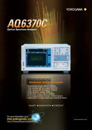
Digital Oscilloscope Mixed Signal Oscilloscope
Digital Oscilloscope Mixed Signal Oscilloscope
Digital Oscilloscope Mixed Signal Oscilloscope

Create successful ePaper yourself
Turn your PDF publications into a flip-book with our unique Google optimized e-Paper software.
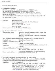
Main Specification<br />
Model<br />
Model name Max. sample rate Frequency bandwidth Max. record length<br />
DL6054 5GS/s 500MHz 6.25Mpts<br />
DLM6054 5GS/s 500MHz 6.25Mpts<br />
DL6014 5GS/s 1GHz 6.25Mpts<br />
DLM6014 5GS/s 1GHz 6.25Mpts<br />
DL6154 10GS/s 1.5GHz 6.25Mpts<br />
Basic Specifications<br />
Input channels DL6000 series 4 analog<br />
DLM6000 series 4 analog + 16 or 32 logic<br />
Analog input<br />
Input coupling setting AC, DC, GND, DC50 Ω<br />
Input impedance 1 MΩ±1.0%, approximately 20 pF<br />
50 Ω±1.5%<br />
Voltage axis sensitivity setting range 1 MΩ: 2 mV/div to 5 V/div (steps of 1-2-5)<br />
50 Ω: 2 mV/div to 500 mV/div (steps of 1-2-5)<br />
Max. input voltage<br />
1 MΩ: 150 Vrms CATl (when frequency is 1 kHz or less)<br />
50 Ω: Must not exceed 5 Vrms or less, or 10 Vpeak<br />
Max. DC offset setting range 1 MΩ<br />
(when probe attenuation is set to 1:1)<br />
Vertical (voltage) accuracy<br />
DC accuracy* 1<br />
2 mV/div to 50 mV/div: ±1 V<br />
100 mV/div to 500 mV/div: ±10 V<br />
1 V/div to 5 V/div: ±100 V<br />
50 Ω<br />
2 mV/div to 50 mV/div: ±1 V<br />
100 mV/div to 500 mV/div: ±5 V<br />
1 MΩ: ±(1.5% of 8 div + offset voltage accuracy)<br />
50 Ω: ±(1.5% of 8 div + offset voltage accuracy)<br />
Offset voltage accuracy* 1 2 mV/div to 50 mV/div: ±(1% of setting + 0.2 mV)<br />
100 mV/div to 500 mV/div: ±(1% of setting + 2 mV)<br />
1 V/div to 5 V/div: ±(1% of setting + 20 mV)<br />
Voltage standing-wave ratio (VSWR) Within frequency band 1.5 or less (typical value* 4 )<br />
Frequency characteristics* 1 * 2<br />
(-3 dB attenuation when inputting a sinewave equivalent in amplitude to ±2 div)<br />
50 Ω DL6054/DLM6054 DL6104/DLM6104 DL6154<br />
0.5 V/div to 10 mV/div DC to 500 MHz DC to 1GMHz DC to 1.5 GHz<br />
5 mV/div DC to 400 MHz DC to 750 MHz DC to 1 GHz<br />
2 mV/div DC to 400 MHz DC to 600 MHz DC to 750 MHz<br />
1 MΩ (with standard passive probe, regulated form the probe tip)<br />
5 V/div to 10 mV/div DC to 500 MHz DC to 500 MHz DC to 500 MHz<br />
5 mV/div to 2 mV/div DC to 400 MHz DC to 400 MHz DC to 400 MHz<br />
Residual noise level* 2 The larger of 0.4 mV rms or 0.05 div rms (typical value* 4 )<br />
A/D resolution<br />
Bandwidth limit<br />
8 bit (25LSB/div)<br />
FULL/200 MHz/20 MHz/8 MHz/4 MHz/2 MHz/1 MHz/500 kHz/250 kHz/<br />
125 kHz/62.5 kHz/32 kHz/16 kHz/8 kHz (can be set for each channel,<br />
can be set independently on CH1 to CH4)<br />
Logic input (DLM6054/DLM6104 only)<br />
Number of inputs<br />
16 or 32 bits<br />
Maximum toggle frequency* 1 Model 701988: 100 MHz<br />
Model 701989: 250 MHz<br />
Compatible probes<br />
701988, 701989 (8 bit input) (701980, 701981 also available)<br />
Min. input voltage<br />
Model 701988: 500mVp-p<br />
Model 701989: 300 mVp-p<br />
Input range<br />
Model 701988: ±40 V<br />
Model 701989: Threshold ±6 V<br />
Max. nondestructive input voltage ±40 V (DC + ACpeak) or 28 Vrms (when using 701989)<br />
Threshold level setting range Model 701988: ±40 V (setting resolution of 0.05 V)<br />
Model 701989: ±6 V (setting resolution of 0.05 V)<br />
Input impedance<br />
Model 701988: Approx. 1 MΩ/approx. 10 pF<br />
Model 701989: Approx. 100 kΩ/approx. 3 pF<br />
Maximum sampling rate<br />
Real time sampling mode DL6054/DL6104/DLM6054/DLM6104 DL6154<br />
Interleave mode ON 5 GS/s 10 GS/s<br />
Interleave mode OFF 2.5 GS/s 5 GS/s<br />
Repetitive sampling mode 2.5TS/s 2.5TS/s<br />
Max. record length 6.25 Mpts 6.25 Mpts<br />
Time axis setting range 500 ps/div to 50 s/div (steps of 1-2-5)<br />
Time base accuracy* 1 ±0.001%<br />
Time axis setting accuracy* 1<br />
Max. acquisition rate* 5<br />
Dead time in N Single mode* 5<br />
Triggers<br />
Trigger modes<br />
Trigger source<br />
Trigger level setting range<br />
CH1 to CH4<br />
EXT<br />
Trigger level setting resolution<br />
CH1 to CH4<br />
EXT<br />
Window Comparator<br />
Center<br />
Width<br />
Trigger level accuracy<br />
CH1 to CH4* 1<br />
EXT* 1<br />
Trigger sensitivity<br />
±(0.001% + 10 ps + 1 sample time)<br />
1.25 Mpts: 60 waveforms/sec/ch<br />
12.5 kpts: 9,000 waveforms/sec/ch<br />
2.5 kpts: 25,000 waveforms/sec/ch<br />
Min. 400 ns or less (equivalent to 2.5 million waveforms/sec)<br />
Auto, Auto Level, Normal, Single, N Single<br />
DL6054/6104/6154 CH1 to CH4, LINE, EXT<br />
DLM6054/DLM6104 CH1 to CH4, LINE, Logic, EXT<br />
±4 div from center of screen<br />
±2 V(1:1), ±20 V (with 10:1 probe)<br />
0.01div<br />
5 mV(1:1), 50 mV (with 10:1 probe)<br />
Can be set on individual channels from CH1 to CH4<br />
±4 div from center of screen<br />
±4 from Center<br />
±(0.2 div + 10% of trigger level)<br />
±(50 mV + 10% of trigger level)<br />
DL6054/DLM6054<br />
CH1 to CH4* 1 1 div p-p DC to 500 MHz DC to 1 GHz<br />
EXT* 1 100 mV p-p DC to 100 MHz DC to 100 MHz<br />
Edge OR* 1 1 div p-p DC to 50 MHz DC to 50 MHz<br />
Trigger type (A trigger)<br />
Edge<br />
Edge<br />
DL6104/DL6154/DLM6104<br />
Triggers on edge of single trigger source (CH1-CH4, Logic, Ext, Line)<br />
Enhanced<br />
Edge/State<br />
Edge (Qualified) Triggers on edge of single trigger source when Qualification<br />
conditions are true (CH1-CH4)<br />
Edge OR<br />
Triggers on edge conditions (OR relationship) of<br />
multiple trigger sources (Max 50 MHz) (CH1-CH4)<br />
State<br />
Triggers on ENTER/EXIT when State conditions are true (CH1 to CH4)<br />
Logic Edge (Qualified) Edge (Qualified) trigger (Logic) with Logic signal as the trigger source<br />
Logic State State trigger (Logic) with Logic signal as the trigger source<br />
Width<br />
Pulse<br />
Triggers on width of a single trigger source (CH1 to CH4)<br />
Pulse (Qualified) Triggers on width of a single trigger source<br />
when Qualification conditions are true (CH1-CH4)<br />
Pulse State Triggers on width when State conditions are true (CH1 to CH4)<br />
Logic Pulse Triggers on width of specified Logic signal pattern (Logic)<br />
Logic Pulse State Pulse State trigger (Logic) with Logic signal as the trigger source<br />
Time width setting mode<br />
More than Triggers when condition changes while time that condition is true is<br />
longer than T1<br />
Less than Triggers when condition changes while time that condition is true is<br />
shorter than T1<br />
Between Triggers when condition changes while time that condition is true is<br />
longer than T1 and shorter than T2<br />
Out of Range Triggers when condition changes while time that condition is true is<br />
shorter than T1 or longer than T2<br />
Time out Triggers when time that condition is true exceeds T1<br />
Setting time (T1/T2) 1 ns to 10 s, 500 ps resolution<br />
Time accuracy ±(0.2% of setting value + 1 ns)<br />
Serial Bus<br />
Serial Pattern General purpose serial communication trigger<br />
Max. bit rate: 50 Mbps; Max. bit length: 128 bits<br />
I2C (optional) (see I2C bus signal analysis function)<br />
SPI (optional) (see SPI bus signal analysis function)<br />
CAN (optional) (see CAN bus signal analysis function)<br />
LIN (optional) (see LIN bus signal analysis function)<br />
UART (optional) (see UART bus signal analysis function)<br />
TV<br />
Triggers on various types of broadcast system video signals<br />
Mode<br />
NTSC/PAL/SDTV/HDTV/UserdefTV<br />
Input CH<br />
CH1-CH4<br />
Sync Guard 60 to 90% of Hsync, steps of 1%<br />
Line<br />
5-1054(NTSC) 2-1251(PAL) 8-2251(SDTV) 2-2251(HDTV) 2-2251(UserdefTV)<br />
Field<br />
1/2/X<br />
Frame Skip 1/2/4/8<br />
Event Interval<br />
Event Cycle Triggers when the event cycle is within the specified time range.<br />
Event Delay After Event 1 occurs, trigger occurs on 1st occurrence of Event 2 that<br />
satisfies the timing constraints. The trigger process is reset if Event<br />
1 or Event 2 occurs before the timing constraints are satisfied.<br />
Event Sequence After Event 1 occurs, trigger occurs on 1st occurrence of Event 2 that<br />
satisfies the timing constraints. The trigger process is not reset if<br />
Event 1 occurs before the timing constraints are satisfied.<br />
Setting time (T1/T2) 1.5ns to 10 s, 500 ps resolution<br />
Time accuracy ±(0.2% of setting value + 1 ns)<br />
Event type<br />
Edge/Edge Qualified/State/Pulse/Pulse Qualified/Pulse State/I2C/CAN/<br />
SPI/Serial<br />
Trigger type (AB triggers)<br />
A Delay B<br />
10 ns to 10 s (B trigger can only be set to Edge)<br />
A to B(N)<br />
1 to 10 9 (B trigger can only be set to Edge)<br />
Display<br />
Display<br />
8.4-inch (21.3 cm) TFT color liquid crystal display<br />
Screen size<br />
170.5 mm (W) 127.9 mm (H)<br />
Total pixels 1024768 (XGA) (waveform display pixels 800640)<br />
Functions<br />
Waveform acquisition/display<br />
Acquisition modes<br />
Normal, Envelope, Average<br />
Other waveform acquisition functions<br />
High Resolution mode (Max. 12 bit equivalent), Repetitive Sampling<br />
mode,Interpolation mode (interpolates up to 1000 times the actually<br />
sampled data),<br />
Roll mode (when the trigger mode is Auto, Auto level, or Single, and the<br />
time width is 100 ms/div to 50 s/div)<br />
Record length<br />
2.5 kpts/6.25 kpts/12.5 kpts/25 kpts/62.5 kpts/125 kpts/250 kpts/<br />
625 kpts/1.25 Mpts/2.5 Mpts/6.25 Mpts<br />
Display format<br />
Analog waveforms can be split into 1, 2, 3, or 4 windows.<br />
Split display of analog and logic waveform domains<br />
(select ratio of 1:1, 1:3, or 3:1).<br />
Bus and State display of logic waveforms.<br />
Accumulation<br />
Select waveform overlapping by Count/Time or Intensity/Color<br />
Snapshot<br />
Currently displayed waveform can be retained on screen<br />
Analysis Functions<br />
Search and Zoom<br />
Auto Scroll<br />
Search functions<br />
Search Type<br />
History memory<br />
Max. data<br />
Zoom up to 2 areas of the displayed waveform along the time axis<br />
(Horizontal Zoom) and voltage axis (Vertical Zoom), with independent<br />
zoom factors.<br />
Automatically scroll the zoom window along the time axis<br />
Search for specific portions of the displayed waveform and display in<br />
the zoom window<br />
Edge/Edge Qualified/State/Pulse/Pulse Qualified/Pulse State/<br />
Serial Pattern/Logic Edge/Logic Edge Qualified/Logic Width/<br />
Logic State/I2C (optional)/SPI (optional)/CAN (optional)/LIN (optional)<br />
2000(2.5 kpts) History<br />
1600(2.5 kpts) N Single<br />
History search<br />
Search for and display waveforms in History memory matching<br />
specified conditions<br />
Search types<br />
Rect/Wave/Polygon/Parameter (Measure/FFT/XY)<br />
Replay<br />
Automatically displays the history waveforms sequentially<br />
Display<br />
Select specified acquisition (#) or average (Avg)<br />
Cursor measurement Vertical/Horizontal/H&V/VT/Marker/Serial<br />
Automated measurement of waveform parameters<br />
Max/Min/High/Low/PP/HighLow/+Over/Over/Rms/Mean/Sdev/<br />
IntegTY/C.Rms/C.Mean/C.Sdev/C.IntegTY/Freq/EdgeCount/Burst/<br />
+Width/-Width/Period/Avg Period/Duty/Rise/Fall/Delay (the following<br />
Mask test<br />
Mask Test Item<br />
Eye pattern Item<br />
are valid when specifying the power supply analysis option)<br />
Umn/Urmn/S/P/Q/Z//Wp/Wp+/Wp-/Abs.Wp/Up-p(P-P)/<br />
U+pk(Max)/U-pk(Min)/Udc(C.Mean)/Urms(C.Rms)/Uac(C.Sdev)/<br />
Imn/Irmn/q/q+/q-/Ads.q/I2t/Ip-p(P-P)/I+pk(Max)/I-pk(Min)/<br />
Idc(C.Mean)/Irms(C.Rms)/Iac(C.Sdev)<br />
Performs Mask Test/Eye Pattern measurement<br />
Wave Count/Wave Count%/Sample Point Count/Sample Point Count%<br />
Vtop/Vbase/top/base/Tcrossing1/Tcrossing2/Vcrossing/Crossing%/<br />
EyeHight/EyeWidth/QFactor/Jitter/DutyCycle/Distortion%/Ext Rate dB/<br />
Rise/Fall<br />
Computations (MATH) Up to 4 traces (M1 to M4)<br />
+/-//Integ/Count(Edge)/Count(Rotary)/Delay/Moving Avg/<br />
LowPass/High Pass/DA/User Defined (user defined MATH option)<br />
Power/Z/I2t (power supply analysis option)<br />
User defined MATH (option)<br />
Reference function<br />
Action ON trigger<br />
Modes<br />
Actions<br />
Analysis<br />
FFT<br />
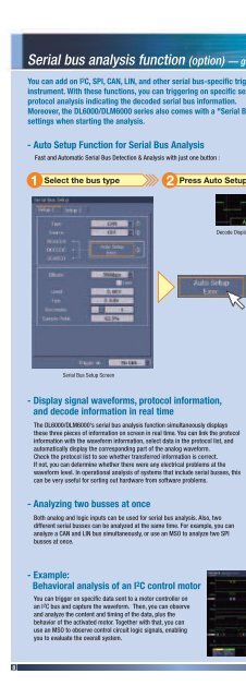
I2C Bus <strong>Signal</strong> Analysis Function (Optional)<br />
The following operators can be arbitrarily combined in equations<br />
+, -, , /, SIN, COS, TAN, ASIN, ACOS, ATAN, INTEG, DIFF, ABS, SQRT,<br />
LOG, EXP, LN, BIN, DELAY, P2 (square), PH, MEAN, HLBT, PWHH,<br />
PWLL, PWHL, PWLH, PWXX, FV, DUTYH, DUTYL, FILT1, FILT2<br />
Up to 4 traces (M1 to M4) of saved waveform data can be displayed<br />
and analyzed (MATH, cursors).<br />
Allows loading and replaying of waveforms in History.<br />
Judges based on automatically measured values of waveform<br />
parameters or waveform zones, and performs the selected action<br />
every time judged to be true.<br />
All Condition/(GO/NOGO Zone/Param)/(GO/NOGO Mask Test)<br />
Buzzer/Print/Save/Mail<br />
XY, Wave Parameter, Accum Histogram,<br />
Serial Bus (optional), Power Analysis(optional)<br />
PS(Up to 250kpts)<br />
Available with /G2 or /G4 option: LS, RS, PSD, CS, TF, CH<br />
Applicable bus I2C bus Bus transfer rate: 3.4 Mbit/s max.<br />
Address mode: 7bits / 10bits<br />
SM bus Complies with System Management Bus<br />
Trigger function<br />
Trigger source CH1 to CH4, Logic<br />
Trigger types Address & Data, Non-Ack, Every Start, General Call,Start Byte,<br />
HS mode<br />
Analyzable no. of data 40,000 bytes max.<br />
Analysis signal input CH1 to CH4, Logic, MATH waveforms (M1 to M4)<br />
Analysis results displays Decode and List displays<br />
Time from reference point, data (Binary/Hex displayed together),<br />
Presence/absence of ACK, R/W, address or data, start condition<br />
Search function<br />
Searches for address patterns, data patterns, and acknowledge bits<br />
Analysis results save function Analysis list data can be saved to CSV-format files<br />
SPI Bus <strong>Signal</strong> Analysis Function (Optional)<br />
Trigger function<br />
Trigger source CH1 to CH4, Logic<br />
Modes<br />
3 wire / 4wire<br />
Bit order<br />
MSB / LSB<br />
Analyzable no. of data 40,000 bytes max.<br />
Analysis signal input CH1 to CH4, Logic, Assignable to MATH waveforms (M1 to M4)<br />
Analysis results displays Decode and List displays<br />
Time from reference point, data<br />
(select Binary or Hex display), CS signal status<br />
Search function<br />
Search for data<br />
Analysis result save function Analysis list data can be saved to CSV-format files<br />
CAN Bus <strong>Signal</strong> Analysis Function (Optional)<br />
CAN bus<br />
CAN version 2.0A/B<br />
Hi-Speed CAN (ISO11898), Low-Speed CAN (ISO11519-2)<br />
Bit rate<br />
1Mbps / 500 kbps / 250 kbps / 125 kbps / 83.3 kbps / User<br />
(can be arbitrarily set with resolution of 100 bps)<br />
Trigger function<br />
Trigger source CH1 to CH4 (input with differential probe)<br />
Trigger types SOF, Error Frame, ID Std/Data, ID Ext/Data, ID/Data OR, Msg/<strong>Signal</strong><br />
Analyzable no. of frames 3,000 frames max.<br />
Analysis signal input CH1 to CH4 or MATH waveforms (M1 to M4)<br />
Analysis results displays Decode and List displays<br />
Frame type, time from trigger point, Frame ID, DLC, Data, CRC,<br />
presence or absence of Ack<br />
Auxiliary analysis functions Data search, field jump, and stuff bit computation functions<br />
Analysis result save function Analysis list data can be saved to CSV-format files<br />
LIN Bus <strong>Signal</strong> Analysis Function (Optional)<br />
LIN bus LIN 1.3 or LIN 2.0<br />
Bit rate<br />
1200 bps, 240 0bps, 4800 bps, 9600 bps, 19200 bps, User, or an<br />
arbitrary bit rate from 1 k to 20 k[bps] (setting resolution of 10 bps).<br />
Trigger function<br />
Trigger source CH1 to CH4, or Logic<br />
Trigger types Break: Triggers when Break<br />
Analysis signal input CH1 to CH4, Logic, or MATH waveforms (M1 to M4)<br />
Analyzable no. of frames 3,000 frames max. (1,500 frames before and after trigger point)<br />
Analysis results displays Decode and List displays<br />
Break, Synch, ID, Data, Checksum, added information (ID parity error,<br />
Checksum error, Wakeup signal)<br />
Auxiliary analysis functions Data search, field jump, and simultaneous analysis (both rev's) functions<br />
Analysis result save function Analysis list data can be saved to CSV-format files<br />
UART <strong>Signal</strong> Analysis Function (Optional)<br />
Bit rate<br />
1200bps, 2400bps, 4800bps, 9600bps, 19200bps, 38400bps,<br />
Select 57600 bps, 115200 bps, User, or an arbitrary bit rate from 1 k<br />
to 200 k[bps] (setting resolution of 0.1 kbps)<br />
Trigger function<br />
Trigger source CH1 to CH4, or Logic<br />
Data format 8bit Data (Non Parity)<br />
7bit Data + Parity bit<br />
8bit Data + Parity bit<br />
Trigger types Every Data: Triggers on Stop Bit position of all data<br />
Analysis signal input CH1 to CH4, Logic, or MATH waveforms (M1 to M4)<br />
Analyzable no. of frames 3,000 bytes max. (1,500 bytes before and after trigger point)<br />
Analysis results displays Decode and List displays<br />
Data, added information (Parity error, Framing error)<br />
Auxiliary analysis functions<br />
Analysis result save function<br />
Data search and field jump functions, ASCII display,and grouping display<br />
Analysis list data can be saved to CSV-format files<br />
Power Supply Analysis (Optional)<br />
Propagation time difference correction (deskew)<br />
The difference in propagation time of voltage and current probe signals<br />
can be automatically or manually corrected.<br />
Correction range is ±80 ns (0.01 ns resolution)<br />
Automated measurement of power supply analysis parameters:<br />
Voltage channels: Umn, Urmn, S, P, Q, Z, , Wp, Wp+, Wp-, Abs.Wp, Up-p(P-P),<br />
Current channels:<br />
U+pk(Max), U-pk(Min), Udc(C.Mean), Urms(C.Rms), Uac(C.Sdev)<br />
Imn, Irmn, q, q+, q-, Abs.q, I2t, Ip-p(P-P), I+pk(Max),I-pk(Min),<br />
Idc(C.Mean), Irms(C.Rms), Iac(C.Sdev)<br />
Statistical processing of measured values:<br />
Enables computation of statistics (Min, Max, Ave, ) from measured values<br />
of power supply analysis items<br />
Waveform computation of power supply analysis parameters:<br />
Active power, impedance, Joule-integral, and FFT waveform computation<br />
can be performed simultaneously with standardwaveform computations.<br />
Harmonic analysis:<br />
Allows for easy comparison with limit values per harmonic current<br />
emission standard IEC 61000-3-2 edition 2.2 (EN61000-3-2 (2000))<br />
Display of the Area of Voltage-Current Operation:<br />
Allows for checking whether it is within the ASO (area of safe operation)<br />
Saving harmonic analysis results: Results of harmonic analysis can be saved to CSV files<br />
Built-in Printer (/B5 Option)<br />
Print type<br />
Thermal line/dot matrix<br />
Paper width<br />
112 mm<br />
Effective print width<br />
104 mm (832 dots)<br />
Auxiliary Input<br />
Rear panel I/O signal External trigger input, external trigger output, GO/NO-GO output,<br />
video output<br />
Probe interface terminal (front panel)<br />
4 terminals<br />
Probe power terminal (rear panel) DL6000 series (with /P2 option) 2 terminals<br />
DLM6000 series (with /P4 option) 4 terminals<br />
Storage<br />
Built-in storage media Capacity Standard approximately 390 MB<br />
(Flash ROM) Option (when /C9 specified) approximately 3.7 GB<br />
Application Saving and loading waveforms/panel settings<br />
USB Peripheral Connection Terminal<br />
Connector USB type A connectors 2<br />
Supported transfer standards LS (Low Speed), FS (Full Speed, 12 Mbps)<br />
Supported devices<br />
USB HID Class Ver 1.1 compliant mouse, 101 keyboard (English)<br />
USB Printer Class Ver 1.0 compliant<br />
USB Mass Storage Class Ver. 1.1 compliant mass storage devices<br />
* Please contact your local Yokogawa sales office for model names of<br />
verified devices<br />
PC Card Interface<br />
Slots<br />
Supported card<br />
1 (rear panel)<br />
GPIB<br />
(National Instruments NI PCMCIA-GPIB card or compatible)<br />
Flash ATA memory card (PC card TYPE II),<br />
CF card + adapter card, various HDD type PC cards<br />
* Please contact your local Yokogawa sales office for model names of<br />
verified devices<br />
USB-PC Connection Terminal<br />
Connector USB type B connector x 1<br />
Supported transfer standards HS (Low Speed), FS (Full Speed)<br />
Supported class<br />
Operates as a multifunction device simultaneously supporting the<br />
following 2 protocols.<br />
USBTMC-USB488(USB Test and Measurement Class Ver.1.0)<br />
Mass Storage Class Ver.1.1 (cannot be formatted)<br />
Ethernet (/C12 and /C9 Options)<br />
Connector RJ-45 connector x 1<br />
Transmission methods Ethernet (100BASE-TX/10BASE-T), LXI 1.2 Class C<br />
Supported services<br />
DHCP, DNS, Microsoft network file sharing server & client, FTP server,<br />
SNTP client, SMTP client, firewall functions<br />
General Specifications<br />
Rated supply voltage<br />
100 to 120 VAC/200 to 240 VAC (auto switching)<br />
Rated supply frequency<br />
50/60Hz<br />
Maximum power consumption 300 VA<br />
Withstand voltage (power supply to case) 1.5 kVAC, for one minute<br />
External dimensions<br />
DL6054/DL6104/DL6154 350(W) 200(H) 178(D) mm<br />
DLM6054/DLM6104 350(W) 200(H) 285(D) mm<br />
(when printer cover closed, excluding protrusions)<br />
Weight<br />
DL6054/DL6104/DL6154 Approx. 6.5 kg (including printer)<br />
DLM6054/DLM6104 Approx. 7.7 kg (including printer)<br />
Operating temperature range 5C˚ to 40C˚<br />
*1: Measured under standard operating conditions after a 30-minute warm-up followed by calibration.<br />
Standard operating conditions<br />
Ambient temperature: 23C˚ ±5C˚<br />
Ambient humidity: 55 ±10% RH<br />
Error in supply voltage and frequency: Within 1% of rating<br />
*2: Value in the case of repetitive phenomenon. The frequency bandwidth of a single-shot phenomenon is the smaller<br />
of the two values, DC to sampling frequency/2.5 or the frequency bandwidth of the repetitive phenomenon<br />
*3: When the input section is shorted, the acquisition mode is set to Normal, interleave mode is OFF, accumulation<br />
is OFF, and the probe attenuation is set to 1:1.<br />
*4: A typical value is a typical or average value. It is not strictly guaranteed.<br />
*5: Acquisition rate does not vary with the increase or decrease in channels.<br />
14<br />
15