Measuring Instruments All Products Guide Vol.10 - Yokogawa
Measuring Instruments All Products Guide Vol.10 - Yokogawa
Measuring Instruments All Products Guide Vol.10 - Yokogawa

Create successful ePaper yourself
Turn your PDF publications into a flip-book with our unique Google optimized e-Paper software.
A<br />
P<br />
<strong>Measuring</strong> <strong>Instruments</strong><br />
<strong>All</strong><br />
<strong>Products</strong><br />
<strong>Guide</strong><br />
G<br />
10<br />
Vol.<br />
Bulletin 00A02B02-60E
New <strong>Products</strong><br />
Mixed Signal Oscilloscopes<br />
DL9700 Series<br />
Mixed Signal Oscilloscopes<br />
DL9500 Series<br />
Digital Oscilloscopes DL9000 (/G4, /F7, /F8 Option)<br />
LIN-bus analysis function<br />
Power supply analysis function<br />
Digital Oscilloscopes<br />
DL1735E<br />
p4<br />
p4<br />
p5<br />
p7<br />
Active Probes<br />
PBA1500(1.5 GHz)<br />
PBA1000(1 GHz)<br />
Precision Power Analyzer WT3000<br />
2A current input element<br />
Precision Optical Power Analyzer Meter WT3000 Optional<br />
Cycle by Cycle measurement(/CC)<br />
Voltage Fluctuation/Flicker measurement(/FL)<br />
Multi Channel Source Measure Unit<br />
GS820<br />
p12<br />
p15<br />
p15<br />
p24<br />
OTDR<br />
AQ7270<br />
Multi Application Test System AQ2200<br />
Sensor Module<br />
Multi Application Test System AQ2200<br />
OSW Module(116)<br />
XFP Interface Module<br />
Data Acquisition Unit DAQMASTER<br />
MW100<br />
MX100<br />
Upgrade<br />
p30<br />
p34<br />
p34<br />
p44<br />
MVAdvanced<br />
MV1000<br />
MV2000<br />
DXAdvanced<br />
DX1000<br />
DX2000<br />
For Green Series Controllers<br />
PC-Based Parameter Setting Tool<br />
LL100/LL200/LL1100/LL1200<br />
Upgrade<br />
Data Acquisition Software Suite<br />
DAQWORX<br />
Upgrade<br />
Upgrade<br />
p47<br />
p51<br />
p58<br />
USB<br />
connection<br />
available<br />
p61<br />
Support for<br />
Windows Vista<br />
Data Logger<br />
Datum-Y XL120<br />
Application Software for Datum-Y<br />
Datum-Logger XL900<br />
Upgrade<br />
Handy Calibrator<br />
CA150<br />
Handy Calibrator<br />
CA11E<br />
CA12E<br />
p62<br />
p62<br />
p64<br />
p65
Contents<br />
Waveform <strong>Measuring</strong> <strong>Instruments</strong><br />
<strong>Measuring</strong> <strong>Instruments</strong> <strong>All</strong> <strong>Products</strong> <strong>Guide</strong> <strong>Vol.10</strong><br />
Digital Oscilloscopes Selection <strong>Guide</strong> .................................................2<br />
DL Series Serial Bus Analyzer Selection <strong>Guide</strong> ..................................2<br />
Scope Corder Series Selection <strong>Guide</strong>.................................................3<br />
Mixed Signal Oscilloscopes .................................................................4<br />
Digital Oscilloscopes............................................................................5<br />
ScopeCorder........................................................................................9<br />
USB2.0 Compliance Test Solution.....................................................11<br />
DL Series Accessories Software .......................................................11<br />
DL Series Accessories List................................................................12<br />
ScopeCorder Series Accessories List ...............................................13<br />
Power <strong>Measuring</strong> <strong>Instruments</strong><br />
Power <strong>Measuring</strong> <strong>Instruments</strong> Selection <strong>Guide</strong>.................................14<br />
Precision Power Analyzer ..................................................................15<br />
Digital Power Meters..........................................................................16<br />
Power Analyzer..................................................................................18<br />
Application software for Power Meters...............................................19<br />
Current Sensor Units .........................................................................19<br />
Current Transducer ............................................................................19<br />
Power <strong>Measuring</strong> <strong>Instruments</strong> Accessories List ................................20<br />
Time Interval Analyzers<br />
Time Interval Analyzers .....................................................................21<br />
Digital Jitter Meters............................................................................21<br />
Function Generators/Universal Counters<br />
Synthesized Function Generators .....................................................22<br />
Universal Counters ............................................................................22<br />
Digital Multimeters/Resistance Meter/Scanner<br />
Digital Multimeters .............................................................................23<br />
Digital Resistance Meter....................................................................23<br />
Scanner .............................................................................................23<br />
Source Measure Units/DC Source<br />
Multi Channel Source Measure Unit..................................................24<br />
Source Measure Unit.........................................................................25<br />
Voltage Current Source .....................................................................25<br />
Temperature <strong>Measuring</strong> <strong>Instruments</strong><br />
Digital Thermometer ..........................................................................26<br />
Pressure <strong>Measuring</strong> <strong>Instruments</strong><br />
Pneumatic Pressure Standard...........................................................26<br />
Digital Manometers............................................................................27<br />
Handheld Digital Manometer .............................................................27<br />
PC-Based <strong>Measuring</strong> <strong>Instruments</strong><br />
PC-Based <strong>Measuring</strong> <strong>Instruments</strong>.....................................................28<br />
Application Software for WE7000 ......................................................29<br />
Communications/Network Test <strong>Instruments</strong><br />
OTDR.................................................................................................30<br />
Handy Optical Powermeters ..............................................................32<br />
LD Light Source.................................................................................32<br />
Traffi c Tester.......................................................................................32<br />
Multi Application Test System ............................................................34<br />
Optical Spectrum Analyzer ................................................................35<br />
High-Resolution Refl ectometer..........................................................37<br />
White Light Source ............................................................................37<br />
WDM Monitor.....................................................................................37<br />
Optical Channel Monitor ....................................................................37<br />
Optical Fiber Strain Analyzer .............................................................37<br />
Fiber Optic Distributed Temperature Unit...........................................37<br />
FBG Sensor Monitor..........................................................................37<br />
Optical <strong>Measuring</strong> <strong>Instruments</strong><br />
Optical Power Meter ..........................................................................38<br />
Multimedia Display Tester ..................................................................38<br />
Light Measurement Data Management Software ..............................38<br />
Mobile/Wireless Test <strong>Instruments</strong><br />
Wireless Communication Tester ........................................................39<br />
WCDMA/GSM Mobile Phone Tester ..................................................39<br />
Shield box with an antenna coupler...................................................39<br />
Baseband Signal Generator ..............................................................40<br />
Wideband Modulation Analyzer .........................................................40<br />
Synthesized Vector Signal Generator ................................................41<br />
Wireless Data Generation & Analysis Utility ......................................41<br />
Recorders<br />
Recorders Selection <strong>Guide</strong>................................................................42<br />
DAQMASTER Series.........................................................................44<br />
MVAdvanced......................................................................................47<br />
Laboratory Recorders........................................................................48<br />
DARWIN Series .................................................................................49<br />
DXAdvanced......................................................................................51<br />
DAQSTATION Series .........................................................................52<br />
Industrial Recorders ..........................................................................54<br />
Control <strong>Products</strong><br />
POWERCERT Power and Energy Meter ...........................................55<br />
UT100 Series Temperature Controllers .............................................55<br />
GREEN Series Digital Indicating Controllers.....................................55<br />
GREEN Series Program Controllers..................................................57<br />
GREEN Series Digital Indicator with Alarms .....................................57<br />
GREEN Series<br />
Digital Indicating Controller with Industrial Ethernet ..........................58<br />
PC-Based Parameters Setting Tools..................................................58<br />
Signal Conditioner .............................................................................59<br />
Data Acquisition Software Suite<br />
DAQWORX Data Acquisition Software Suite.....................................61<br />
DAQOPC OPC Interface Package.....................................................61<br />
Portable Test <strong>Instruments</strong><br />
Data Logger.......................................................................................62<br />
Clamp-on Power Meters ....................................................................63<br />
Handy Calibrators ..............................................................................64<br />
Digital Multimeters .............................................................................66<br />
Clamp-on Testers...............................................................................68<br />
Digital Insulation Tester......................................................................70<br />
Analog Insulation Testers...................................................................71<br />
Earth Tester .......................................................................................72<br />
Leakage Current Tester .....................................................................72<br />
Digital Illuminance Meters..................................................................72<br />
Digital Thermometers ........................................................................72<br />
Thermo-Collectors .............................................................................73<br />
Standard Resistors ...........................................................................74<br />
Decade Resistance Boxes.................................................................74<br />
Slide Resistors...................................................................................74<br />
Portable Wheatstone Bridge..............................................................74<br />
Precision Double Bridge ....................................................................74<br />
Meters <strong>Products</strong><br />
Portable <strong>Instruments</strong>..........................................................................75<br />
Switchboard <strong>Instruments</strong> ...................................................................75<br />
Panel Meters......................................................................................75<br />
0.5 Class Transducer for Power Applications.....................................75<br />
<strong>Products</strong> with this mark conform to the EMC standards (reg u la tions<br />
on electromagnetic interference) of European Community.<br />
Waveform<br />
<strong>Measuring</strong><br />
<strong>Instruments</strong><br />
Power<br />
<strong>Measuring</strong><br />
<strong>Instruments</strong><br />
Time Interval<br />
Analyzers<br />
Function<br />
Generators/<br />
Universal<br />
Counters<br />
Digital<br />
Multimeters/<br />
Resistance<br />
Meter/Scanner<br />
Source<br />
Measure Units/<br />
DC Source<br />
Temperature<br />
<strong>Measuring</strong><br />
<strong>Instruments</strong><br />
Pressure<br />
<strong>Measuring</strong><br />
<strong>Instruments</strong><br />
PC-Based<br />
<strong>Measuring</strong><br />
<strong>Instruments</strong><br />
Communications/<br />
Network Test<br />
<strong>Instruments</strong><br />
Optical<br />
<strong>Measuring</strong><br />
<strong>Instruments</strong><br />
Mobile/<br />
Wireless Test<br />
<strong>Instruments</strong><br />
Recorders<br />
Control<br />
<strong>Products</strong><br />
Data<br />
Acquisition<br />
Software<br />
Suite<br />
Portable Test<br />
<strong>Instruments</strong><br />
Meters<br />
<strong>Products</strong><br />
1
Waveform <strong>Measuring</strong> <strong>Instruments</strong><br />
Waveform<br />
<strong>Measuring</strong><br />
<strong>Instruments</strong><br />
Waveform <strong>Measuring</strong><br />
Digital Oscilloscopes Selection <strong>Guide</strong><br />
http://www.yokogawa.com/tm/dl/tm-dl.htm<br />
• The DL series digital oscilloscopes have high-speed sampling and a wide range of bandwidths that can be utilized for design and development of<br />
electronic devices.<br />
They can also execute computations on repetitive waveforms and automatically extract waveform parameters.<br />
The DL Series offers an extensive selection of digital oscilloscopes with large-capacity memories, powerful triggering func tions, unique History Memory<br />
function and internal printers. It also can save and load data to and from internal or external media.<br />
Model<br />
DL9700L/DL9500L Series<br />
DL9040/9140/9240 Series<br />
DL7400 series DL1700E series DL1600 series<br />
Item<br />
Features<br />
Max. Sampling Rate<br />
Bandwidth<br />
Number of analog input channels<br />
Logic Input<br />
Max. vertical sensitivity (1:1)<br />
Vertial axis resolution<br />
Max. sweep sensitivity<br />
Max. record length St’d<br />
Internal Media drive<br />
Internal HDD<br />
Interface<br />
Internal printer<br />
Others<br />
Display (TFT LCD)<br />
External Dimensions<br />
W × H × D (mm)<br />
Weight (kg)<br />
St’d<br />
selectable<br />
Optional<br />
St’d<br />
Optional<br />
St’d/<br />
Optional<br />
Optional<br />
Analog 4ch+Logic 32/16bits<br />
input<br />
Max. 5GS/s<br />
Serial bus analysis<br />
functions<br />
Power supply analysis<br />
functions<br />
"Virtual DA" functions<br />
Probe power connectors<br />
Supports USB Storage<br />
USB mouse/keyboard<br />
*1: See each product catalog for more detaled specifications<br />
*2: Depends on model<br />
5GS/s<br />
1.0GHz (*2)<br />
4<br />
DL9705L, DL9710L: St'd:32 (8bits × 4)<br />
DL9505L, DL9510L: St'd:16 (8bits × 2)<br />
2 mV/div<br />
8 bit<br />
500 ps/div<br />
6.25 MW<br />
PC card (2)<br />
–<br />
40 GB (FAT32)<br />
USB<br />
Ethernet<br />
Optional: 112 mm width<br />
I 2 C bus analysis<br />
SPI bus analysis<br />
CAN & LIN bus analysis<br />
Probe power connectors<br />
Power supply analysis<br />
functions<br />
User define math functions<br />
8.4-inch color, XGA<br />
350 × 200 × 285<br />
Approx. 7.7<br />
DL Series Serial Bus Analyzer Selection <strong>Guide</strong><br />
Fast screen update & all<br />
points display<br />
Compact & lightweight, 4 ch<br />
Max. 10 GS/s<br />
I 2 C, SPI, CAN and LIN bus<br />
analysis functions<br />
Probe power connectors<br />
Supports USB Storage<br />
USB mouse/keyboard<br />
Power supply analysis<br />
functions<br />
10 GS/s (*2)<br />
1.5 GHz (*2)<br />
4<br />
–<br />
2 mV/div<br />
8 bit<br />
500 ps/div<br />
DL9040, DL9140, DL9240:2.5 MW<br />
DL9040L, DL9140L, DL9240L:6.25 MW<br />
PC card<br />
–<br />
40 GB (FAT32)<br />
USB<br />
Ethernet<br />
Optional: 112 mm width<br />
I 2 C bus analysis<br />
SPI bus analysis<br />
CAN & LIN bus analysis<br />
Probe power connectors<br />
Power Supply analysis<br />
functions<br />
User define math functions<br />
8.4-inch color, XGA<br />
350 × 200 × 178<br />
Approx. 6.5<br />
Fast screen update & all points<br />
display<br />
High speed 8 ch + 16 bits logic<br />
input<br />
Max. 2 GS/s<br />
Web server function<br />
Serial bus analysis functions<br />
Power analysis functions<br />
USB mouse/keyboard<br />
Probe power connectors<br />
Supports USB Storage<br />
FlexRay Signal Analyzer<br />
2 GS/s<br />
500 MHz<br />
DL7440/7480: 4 ch/8 ch<br />
St’d: 16-bit (8 bits × 2)<br />
2 mV/div<br />
8 bit<br />
1 ns/div<br />
701450/70: 4 MW<br />
701460/80: 16 MW<br />
PC card<br />
FDD, Zip ®<br />
–<br />
USB/GP-IB<br />
Ethernet/SCSI<br />
Optional: 112 mm width<br />
I 2 C bus analysis<br />
CAN bus analysis<br />
SPI bus analysis<br />
User-defined Math<br />
Power Analysis<br />
Four additional probe power<br />
(total: 8, DL7480 only) ( * 3)<br />
FlexRay bus analysis<br />
8.4-inch color, VGA<br />
373 × 210.5 × 355.3<br />
Approx. 10<br />
Fast screen update & all<br />
points display<br />
Compact & lightweight, 4 ch<br />
Max. 1 GS/s<br />
I 2 C, SPI bus analysis<br />
functions<br />
Probe power connectors<br />
Supports USB Storage<br />
Web server functions<br />
USB mouse/keyboard<br />
1 GS/s<br />
500 MHz (*2)<br />
DL1720E/DL1735E, 40E, 40EL: 2 ch/4 ch<br />
–<br />
2 mV/div<br />
8 bit<br />
1 ns/div<br />
DL1740EL: 8 MW<br />
DL1740E: 2 MW<br />
DL1735E: 2 MW<br />
DL1720E: 1 MW<br />
–<br />
FDD, PC card<br />
–<br />
USB/GP-IB<br />
Ethernet<br />
Optional: 112 mm width<br />
I 2 C bus analysis (SPI)<br />
2/4 output Probe Power<br />
Connectors<br />
6.4-inch color, VGA<br />
220 × 266 × 264<br />
Approx. 5.5<br />
*3: The DL7400 series comes standard with four probe power connectors.<br />
Fast screen update & all<br />
points display<br />
Compact 4 ch, 200 MS/s<br />
Max. 32 MW memory (4 ch)<br />
Web server functions<br />
Serial bus analysis<br />
functions (CAN, I 2 C, SPI)<br />
USB mouse/keyboard<br />
Probe power connectors<br />
Supports USB Storage<br />
200 MS/s<br />
200 MHz<br />
DL1620/1640/1640L: 2 ch/4 ch/4 ch<br />
–<br />
2 mV/div<br />
8 bit<br />
2 ns/div<br />
DL1620/DL1640: 8 MW<br />
DL1640L: 32 MW<br />
–<br />
PC card, FDD, Zip ®<br />
–<br />
RS232<br />
USB/Ethernet/GP-IB<br />
Optional: 112 mm width<br />
I 2 C bus Analysis (SPI)<br />
CAN bus Analysis (SPI)<br />
2/4 Output Probe Power<br />
Connecors<br />
DC/Battery powered model<br />
(DC 12 V + Battery)<br />
6.4-inch color, VGA<br />
220 × 266 × 224<br />
Approx. 3.9<br />
Bus Types<br />
I 2 C<br />
CAN<br />
Functions<br />
Models<br />
DL9700L/9500L Series DL9040/9140/9240 Series DL7400 Series DL1700E Series DL1600 Series<br />
Triggers <br />
Trigger Types<br />
Address & data/Non-Ack/Every<br />
start/General Call/Start byte/HS<br />
mode<br />
Address & data/Non-Ack/Every<br />
start/General Call/Start byte/HS<br />
mode<br />
Start/Non-ACK/Address & Data<br />
Analysis & Search (*1) (*1) <br />
Triggers <br />
Trigger Types<br />
SOF/Error Frame/ID Std/Data,<br />
ID Ext/Data/ID/Data OR<br />
SOF/Error Frame/ID Std/Data,<br />
ID Ext/Data/ID/Data OR<br />
SOF/Identifi er/RTR/Data<br />
Field/Error Frame<br />
—<br />
SOF/Identifi er/RTR/Data<br />
Field/Error Frame<br />
Analysis & Search (*1) (*1) <br />
Triggers <br />
LIN<br />
Trigger Types Synch Break — — —<br />
Analysis & Search (*1) (*1) <br />
Triggers <br />
SPI<br />
Trigger Types 3wire/4wire 3wire/4wire A pattern, B pattern, A B pattern, Byte count —<br />
Analysis & Search (*1) (*1) <br />
Triggers <br />
FlexRay<br />
Trigger Types — —<br />
Frame Start/Payload preamble,<br />
Null frame, Sync Frame,<br />
Startup Frame indicators/Frame<br />
ID/Cycle count (Payload) Data.<br />
CRC Error Trigger<br />
— —<br />
Analysis & Search <br />
2<br />
: Standards, : Optional, : NA<br />
*1: Real-time Analysis and Display
Waveform <strong>Measuring</strong> <strong>Instruments</strong><br />
Waveform <strong>Measuring</strong><br />
ScopeCorder Series Selection <strong>Guide</strong><br />
http://www.yokogawa.com/tm/sl/tm-sl.htm<br />
Waveform<br />
<strong>Measuring</strong><br />
<strong>Instruments</strong><br />
• The ScopeCorder series can be used to capture single-shot or infrequently recurring signals.<br />
They can also execute computations on repetitive waveforms, and automatically extract waveform parameters.<br />
The ScopeCorder series offers an extensive selection with large-capacity memories, powerful triggering func tions, and internal print ers. It also can save and<br />
load data to and from internal or external media.<br />
DL750P and SL1400 can provide big paper output capability for many applications in the fi eld.<br />
Model<br />
DL750<br />
DL750P<br />
SL1400<br />
Item<br />
Features<br />
Compact, 16 ch isolated inputs<br />
(8 module slots)<br />
GigaZoomEngine and Max 1<br />
GW<br />
Dual Capture<br />
Eleven kinds of plug-in input<br />
modules<br />
Web server functions<br />
A6 (112 mm) printer<br />
Probe power connectors<br />
Compact, 16 ch isolated inputs<br />
(8 module slots)<br />
GigaZoomEngine and Max 1<br />
GW<br />
Dual Capture<br />
Eleven kinds of plug-in input<br />
modules<br />
Web server functions<br />
A4 (210 mm) Big Printer<br />
Probe power connectors<br />
Compact, 16 ch isolated inputs<br />
(8 module slots)<br />
Eleven kinds of plug-in input<br />
modules<br />
Web server functions<br />
A4 (210 mm) Big Printer<br />
Probe power connectors<br />
Max. sampling rate<br />
Bandwidth<br />
Number of analog input channels<br />
Logic input<br />
10 MS/s ( * 2)<br />
3 MHz ( * 2)<br />
Plug-in module: 16 ch (isolation)<br />
St’d: 16 (8 bits × 2)<br />
10 MS/s ( * 2)<br />
3 MHz ( * 2)<br />
Plug-in module: 16 ch (isolation)<br />
St’d: 16 (8 bits × 2)<br />
10 MS/s ( * 2)<br />
3 MHz ( * 2)<br />
Plug-in module: 16 ch (isolation)<br />
St’d: 16 (8 bits × 2)<br />
Max. vertical sensitivity (1:1)<br />
Vertial axis resolution<br />
Max. sweep sensitivity<br />
Max. record length St’d<br />
100 µV/div ( * 2)<br />
Max. 16 bits ( * 2)<br />
500 ns/div ( * 2)<br />
50 MW max/2.5 MW (16 ch)<br />
100 µV/div ( * 2)<br />
Max. 16 bits ( * 2)<br />
500 ns/div ( * 2)<br />
50 MW max/2.5 MW (16 ch)<br />
1 mV range<br />
Max. 16 bits ( * 2)<br />
100 µs Setting<br />
50 MW max/2.5 MW (16 ch)<br />
Internal media drive<br />
Internal HDD<br />
Interface<br />
Internal printer<br />
Others<br />
Display (TFT LCD)<br />
External dimensions<br />
W × H × D (mm)<br />
Weight (kg)<br />
Optional<br />
selectable<br />
Optional<br />
St’d<br />
Optional<br />
St’d<br />
Optional<br />
*1: See each product catalog for more detaled specifications<br />
*2: Depends on input module<br />
*3: Plug-in modules are not included<br />
1 GW max/50 MW (16 ch)<br />
PC card, FDD and Zip<br />
40 GB (FAT32)<br />
USB/GP-IB/RS232/SCSI<br />
Ethernet<br />
112 mm width<br />
DSP channels<br />
User-defined Math computations<br />
Probe Power Connectors<br />
DC 12 V model available<br />
10.4-inch color, SVGA<br />
355 × 250 × 180<br />
Approx. 6.6 * 3<br />
1 GW max/50 MW (16 ch)<br />
PC card, FDD<br />
40 GB (FAT32)<br />
USB/GP-IB/RS232/SCSI<br />
Ethernet<br />
210 mm width<br />
DSP channels<br />
User-defined Math computations<br />
Probe Power Connectors<br />
10.4-inch color, SVGA<br />
355 × 250 × 225<br />
Approx. 8.0 * 3<br />
–<br />
PC card<br />
40 GB (FAT32)<br />
USB/GP-IB/RS232/SCSI<br />
Ethernet<br />
210 mm width<br />
Probe Power Connectors<br />
10.4-inch color, SVGA<br />
355 × 250 × 225<br />
Approx. 8.0 * 3<br />
Analog<br />
Voltage<br />
Temperature<br />
Temperature<br />
Acceleration<br />
Strain<br />
Input<br />
Frequency<br />
Model No.<br />
701250<br />
701251<br />
701260<br />
701261/62<br />
701255<br />
701265<br />
701275<br />
701270<br />
701271<br />
Sample Rate /<br />
Resolution<br />
10MS/s, 12-bit<br />
1MS/s, 16-bit<br />
100kS/s, 16-bit<br />
100kS/s (Voltage),<br />
500S/s (Temperature)<br />
10MS/s, 12-bit<br />
500S/s, 16-bit<br />
100kS/s, 16-bit<br />
100kS/s, 16-bit<br />
100kS/s, 16-bit<br />
Channel<br />
Number<br />
Isolation<br />
2<br />
2<br />
2<br />
2<br />
2<br />
2<br />
2<br />
2<br />
2<br />
Isolated<br />
Isolated<br />
Isolated<br />
Isolated<br />
Nonisolated<br />
Isolated<br />
Isolated<br />
Isolated<br />
Isolated<br />
Maximum Input Voltage<br />
DC Accuracy<br />
600 V * 4<br />
± 0.5%<br />
250 V * 5<br />
600 V * 4<br />
± 0.25%<br />
140 V * 5<br />
1000 V * 4<br />
± 0.25%<br />
850 V * 5<br />
42 V ± 0.25% (Voltage)<br />
600 V * 4 * 6<br />
± 0.5%<br />
250 V * 5<br />
42 V ± 0.08% (Voltage)<br />
± 0.25% (Voltage)<br />
42 V<br />
± 0.5% (Acceleration)<br />
42 V ± 0.5% (Strain)<br />
42 V ± 0.5% (Strain)<br />
42 V * 5<br />
Features<br />
10 MS/s, 12 bit, broad bandwidth (3 MHz), high accuracy (0.5%), high noise immunity<br />
1 MS/s, 16 bit, bandwidth: 300 kHz, high accuracy (0.25%)<br />
High sensitivity range (10 mV), low noise (±100 µVtyp), and high noise immunity<br />
High voltage (direct 850 V input), high accuracy (0.25%), with RMS, and high noise<br />
immunity<br />
Universal modules (voltage/temperature), voltage 100 kS/s, 16-bit, temperature 500 S/s<br />
Voltage (50 mV to 200 V range), thermocouple (K, E, J, T, L, U, N, R, S, B, W, iron-doped gold/chromel), with AAF (701262)<br />
10 MS/s, 12-bit Non-Isolation (non-isolation version of model 701250)<br />
Both temperature and voltage input, frequency range of 100 Hz, thermocouple (K, E, J, T, L, U, N, R, S, B, W,<br />
iron-doped gold/chromel), High accuracy voltage (0.08%), high sensitivity range (1 mV), and low noise (±4µVtyp)<br />
Both acceleration and voltage input, built-in anti-aliasing filter<br />
Supports built-in amp type acceleration sensors (4 mA/22 V)<br />
Supports strain NDIS, high accuracy (0.5%), 2, 5, 10 V built-in bridge power supply<br />
Supports strain DSUB, high accuracy (0.5%), 2, 5, 10 V built-in bridge power supply, and shunt CAL<br />
420 V * 4<br />
Measurement frequency of 0.01 Hz to 200 kHz, Measured parameters<br />
701280 25kS/s, 16-bit 2 Isolated<br />
± 0.1% (Frequency)<br />
(frequency, rpm, period, duty, power supply frequency, distance, speed)<br />
*4, When using the 10:1 Isolation probe (700929). *5, When using the 1:1 safety adapter lead (701901). *6, When using the 10:1 passive probe (701940)<br />
3
Waveform <strong>Measuring</strong> <strong>Instruments</strong><br />
Waveform<br />
<strong>Measuring</strong><br />
<strong>Instruments</strong><br />
Mixed Signal<br />
Oscilloscopes<br />
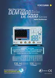
DL9000 Series MSO Models<br />
http://www.yokogawa.com/tm/DL9710L/<br />
High performance and compact Mixed Signal Oscilloscope with<br />
4 analog channels and 16/32-bit Logic input<br />
Features<br />
• Simultaneous measurement and analysis of 4 analog channels +<br />
16/32-bit logic<br />
• High speed acquisition and quick response<br />
• Fast and powerful analysis of logic channels<br />
• Capture and separate anomalies easily with History Memory<br />
• Extensive trigger functions for handling the most complex waveforms<br />
• Versatile zoom and search functions<br />
• “Virtual D/A” Function<br />
• Serial Bus Analysis (I 2 C, SPI, CAN, LIN) (optional)<br />
• Power Supply Analysis (optional)<br />
Model DL9710L DL9705L DL9510L DL9505L<br />
Basic Specifi cations<br />
Analog inputs<br />
Analog Bandwidth DC-1GHz(DL9710L, DL9510L)<br />
DC-500MHz(DL9705L, DL9505L)<br />
Analog input<br />
4ch<br />
Vertical sensitivity for 1MΩ input 2mV/div to 5V/div<br />
for 50Ω input 2mV/div to 500mV/div<br />
DC accuracy<br />
±(1.5% of 8div + offset voltage accuracy)<br />
Vertical axis resolution 8-bit<br />
Logic inputs<br />
Number of input<br />
32bits(8bits × 4) (DL9710L, DL9705L)<br />
16bits(8bits × 2) (DL9510L, DL9505L)<br />
Maximum toggle frequency<br />
250 MHz (701981)<br />
Input voltage range ±10 V (DC + AC peak, 701981)<br />
Logic Threshold level ±10 V (0.1 V setting resolution, 701981)<br />
Input impedance approx. 10kΩ/approx. 9 pF (701981)<br />
Common Specifi cations<br />
Max. sampling rate 5GS/s<br />
Sweep sensitivity 500ps/div to 50s/div<br />
Max. record length 6.25MW<br />
History memory Max data: 2000 (2.5 kW), when using history<br />
1600 (2.5 kW), when in N single mode<br />
Trigger modes Auto, Auto Level, Normal, Single, and N<br />
Single<br />
Trigger types<br />
Edge/State, Width, Event Interval,<br />
TV, Serial Bus(I 2 C, SPI, CAN, LIN),<br />
Serial Pattern<br />
Internal media drive Flash ROM, 90MByte<br />
Interface<br />
USB Peripheral support, PC Card Interfaces,<br />
USB-PC Connection, Ethernet (optional)<br />
Internal printer (optional) Thermal line-dot, width 112mm<br />
Other options<br />
Serial Bus analysis (I 2 C, SPI, CAN, LIN),<br />
User-defi ned Math, Power supply analysis,<br />
Internal HDD, Probe Power supply<br />
Display (TFT LCD) 8.4-inch color TFT LCD<br />
External dimensions 350(W) × 200(H) × 285(D)mm<br />
Weight<br />
Approx. 7.7kg (excluding printer)<br />
Analog inputs channels<br />
4ch<br />
Analog Frequency Bandwidth 1GHz 500MHz 1GHz 500MHz<br />
Logic inputs channels 32bits 16bits<br />
Max. Logic toggle frequency<br />
250MHz<br />
Max. Sampling Speed<br />
5GS(Simultaneous sampling of analog and logic)<br />
701320<br />
701321<br />
701330<br />
701331<br />
Model Number and Suffi x Codes<br />
Model Suffix Code Description<br />
-D<br />
-F<br />
Power Cable -Q<br />
-R<br />
-H<br />
Help menu language -HE<br />
-L0<br />
Logic Probe -L2<br />
-L4 *1<br />
Options<br />
/B5<br />
/P4 *2<br />
/C8 *3<br />
/C10 *3<br />
/G2 *4<br />
/G4 *4<br />
/F5 *5<br />
/F7 *5<br />
/F8 *5<br />
DL9505L: 4ch 500MHz + Logic 16bits<br />
Max. 5 GS/s(2.5 GS/s/ch), 6.25 MW/ch<br />
DL9510L: 4ch 1GHz + Logic 16bits<br />
Max. 5 GS/s(2.5 GS/s/ch), 6.25 MW/ch<br />
DL9705L: 4ch 500MHz + Logic 32bits<br />
Max. 5 GS/s(2.5 GS/s/ch), 6.25 MW/ch<br />
DL9710L: 4ch 1GHz + Logic 32bits<br />
Max. 5 GS/s(2.5 GS/s/ch), 6.25 MW/ch<br />
UL/CSA standard<br />
VDE standard<br />
BS standard<br />
AS standard<br />
GB standard<br />
English Help<br />
No Logic Probe attached<br />
Attach two 250 MHz Logic Probes (701981)<br />
Attach four 250 MHz Logic Probes (701981)<br />
Built-in printer<br />
4 Probe power connections on rear panel<br />
Built-in HDD + Ethernet interface<br />
Ethernet interface<br />
User-defined math function<br />
Power Supply Analysis Function<br />
I 2 C+SPI bus analyzer<br />
CAN+LIN+SPI bus analyzer<br />
I 2 C+CAN+LIN+SPI bus analyzer<br />
*1: Not available for DL9500 series<br />
*2: Please order /P4 option if you use either current probes or differential probes such as<br />
701920, 701922.<br />
*3: Choose either one<br />
*4: Choose either one<br />
*5: Choose either one. I 2 C, CAN, LIN and SPI triggers are standard.<br />
4
Waveform <strong>Measuring</strong> <strong>Instruments</strong><br />
Digital Oscilloscopes<br />
DL9000<br />
http://www.yokogawa.com/tm/DL9000/<br />
Waveform<br />
<strong>Measuring</strong><br />
<strong>Instruments</strong><br />
High-Performance 500 MHz/1 GHz/1.5 GHz Bandwidth Digital<br />
Oscilloscopes<br />
Overview<br />
The DL9000 signalXplorer is <strong>Yokogawa</strong>’s10(X)th<br />
generation digital oscilloscope. It allows users to select<br />
the most appropriate memory setting for a given<br />
measurement and then acquires and displays long and<br />
short memory records quickly, saving the wave forms to<br />
its segmented memory.<br />
Advanced memory handling en sures that you get all<br />
the benefi ts of a long memory scope regardless of the<br />
record size you allocate for each acquisition. This is<br />
made possible by the state-of-the-art ADSE (advanced<br />
data stream engine) ASIC.<br />
Features<br />
DL9000<br />
Basic Specifi cations<br />
Max. sampling rate<br />
5 GS/s (2 channels) 2.5 GS/s (4 chan nels) (DL9040/<br />
DL9040L/DL9140/DL9140L)<br />
10 GS/s (2 channels) 5 GS/s (4 channels)<br />
(DL9240/DL9240L)<br />
Bandwidth 500 MHz (DL9040/DL9040L)<br />
1 GHz (DL9140/DL9140L)<br />
1.5 GHz (DL9240/DL9240L)<br />
Number of analog input channels<br />
4 input channels<br />
Vertical sensitivity<br />
For 1 MΩ input: 2 mV/div to 5 V/div (steps of 1-2-5)<br />
For 50 Ω input: 2 mV/div to 500 mV/div (steps of 1-2-5)<br />
DC accuracy For 1 MΩ input: ±(1.5% of 8 div + offset voltage ac cu ra cy)<br />
For 50 Ω input: ±(1.5% of 8 div + offset voltage ac cu ra cy)<br />
Vertial axis resolution<br />
8-bit (25 LSB/div)<br />
Sweep sensitivity<br />
500 ps/div to 50 s/div (steps of 1-2-5)<br />
Max. record length<br />
2.5 M word/channel (DL9040/DL9140/DL9240)<br />
6.25 M word/channel (DL9040L/DL9140L/DL9240L)<br />
Internal media drive<br />
Flash ROM,Capacity 90 MB<br />
Interface USB Peripheral Support/PC Card Interfaces/<br />
USB-PC Connections/Ethernet Communication (/C10<br />
and /C8 Options)<br />
Internal printer Thermal line-dot, Paper width 112 mm (option)<br />
Other options I 2 C Analysis Function, SPI Anal y sis Function, CAN<br />
Anal y sis Function, LIN Analysis Function, In ter nal<br />
Hard Disk Drive, User-defi ned math function, Power<br />
supply analysis function<br />
Display (TFT LCD)<br />
8.4-inch (21.3 cm) color TFT liquid crystal display<br />
External dimensions<br />
350 (W) × 200 (H) × 178 (D) mm<br />
(when printer cover is closed, excluding han dle and<br />
protrusions)<br />
Weight (kg) Approx. 6.5 kg<br />
• 4 input channels<br />
• Analog BW<br />
500 MHz (DL9040/DL9040L)<br />
1 GHz (DL9140/DL9140L)<br />
1.5 GHz (DL9240/DL9240L)<br />
• Max. sampling rate<br />
5 GS/s (2 channels) 2.5 GS/s(4 channels) (DL9040/DL9040L/DL9140/<br />
DL9140L)<br />
10 GS/s (2 channels) 5 GS/s (4 channels) (DL9240/DL9240L)<br />
• Max. record length<br />
2.5 M word/channel (DL9040/DL9140/DL9240)<br />
6.25 M word/channel (DL9040L/DL9140L/DL9240L)<br />
• Fast acquisition rate<br />
Max. 2.5 M waveforms/sec/ch<br />
• History memory function<br />
Review & analyze up to 2,000 of the most re cent waveforms after the<br />
ac qui si tion is stopped<br />
• Compact and light weight<br />
18 cm (7.1") depth, 6.5 kg (14.5 lbs.)<br />
Model Number and Suffi x Codes<br />
Model and Suffix Codes of DL9040/9140/9240<br />
Model Suffix Code<br />
701307<br />
701308<br />
701310<br />
701311<br />
701312<br />
701313<br />
Power cable -D<br />
-F<br />
-Q<br />
-R<br />
-H<br />
Help menu language -HE<br />
-HC<br />
-HK<br />
/B5<br />
/P2 1<br />
Options<br />
DL9040 digital oscilloscope<br />
500 MHz max. 5 GS/s (2.5 GS/s/ch),<br />
2.5 Mword/ch<br />
DL9040L digital oscilloscope<br />
500 MHz max. 5 GS/s (2.5 GS/s/ch),<br />
6.25 Mword/ch<br />
DL9140 digital oscilloscope<br />
1 GHz max. 5 GS/s (2.5 GS/s/ch),<br />
2.5 Mword/ch<br />
DL9140L digital oscilloscope<br />
1 GHz max. 5 GS/s (2.5 GS/s/ch),<br />
6.25 Mword/ch<br />
DL9240 digital oscilloscope<br />
1.5 GHz max. 10 GS/s (5 GS/s/ch),<br />
2.5 Mword/ch<br />
DL9240L digital oscilloscope<br />
1.5 GHz max. 10 GS/s (5 GS/s/ch),<br />
6.25 Mword/ch<br />
UL/CSA standard<br />
VDE standard<br />
BS standard<br />
AS standard<br />
GB standard<br />
English Help<br />
Chinese Help<br />
Korean Help<br />
Built-in printer<br />
Probe power connections on rear panel<br />
(2 outputs for 900 MHz FET probe and current probe)<br />
Built-in hard disk + Ethernet interface<br />
Ethernet interface<br />
User-defined math<br />
Power supply analysis (included user-defined math)<br />
I 2 C + SPI bus analyzer<br />
CAN + LIN + SPI bus analyzer<br />
Description<br />
/C8 2<br />
/C10 2<br />
/G2 2<br />
/G4 2<br />
/F5 3<br />
/F7 3<br />
/F8 3 I 2 C + CAN + LIN + SPI bus analyzer<br />
1: Please specify this /P2 option if you use either current probes or differential probes such as<br />
701920 or 701922.<br />
2: Choose either one.<br />
3: Choose either one. I 2 C, CAN, LIN and SPI bus signal triggers are standard.<br />
5
Waveform <strong>Measuring</strong> <strong>Instruments</strong><br />
Waveform<br />
<strong>Measuring</strong><br />
<strong>Instruments</strong><br />
Digital Oscilloscopes<br />
DL7440/DL7480<br />
http://www.yokogawa.com/tm/DL7400/<br />
The DL7400 Series <strong>All</strong>ows Multi-channel Capture of Analog and<br />
Logic Signals<br />
Overview<br />
The DL7400 Series includes 4 and 8-channel analog<br />
input models. Each model has up to 16-bit logic<br />
inputs. <strong>All</strong> these inputs come in a convenient,<br />
benchtop-sized in stru ment. In additon to<br />
capturing up to 16 logic sig nals, the DL7400 Series<br />
lets you si mul ta neous ly mea sure up to 8 analog<br />
signals with out need ing to syn chro nize two<br />
separate os cil lo scopes.<br />
6<br />
DL7440<br />
DL7480<br />
Basic Specifi cations<br />
Input channels 4/8 analog (depends on model), and 16-bit logic<br />
Voltage axis sensitivity setting range<br />
For 1 MΩ input: 2 mV/div to 10 V/div (steps of 1, 2, or 5)<br />
For 50 Ω input: 2 mV/div to 1 V/div (steps of 1, 2, or 5)<br />
Frequency characteristics<br />
For 1 MΩ input: (using passive probe model 700988;<br />
spec i fi ed at probe tip) 10 V/div to 10 mV/div: DC to<br />
400 MHz (500 MHz * )<br />
*: When using Miniature passive probe model 701941;<br />
specifi ed at probe tip.<br />
A/D conversion resolution<br />
8 bits (24 LSB/div)<br />
Maximum sampling rate<br />
2 GS/s<br />
Maximum record length<br />
701450/701470: 4 MW/channel<br />
701460/701480: 16 MW/channel<br />
DC accuracy ±(1.5% of 8 div + offset voltage accuracy)<br />
Time axis setting range<br />
1 ns/div to 50 s/div (for record length of 10 kW or great er)<br />
Display 8.4-inch color TFT liquid crystal display<br />
Built-in printer (optional)<br />
Paper width: 112 mm<br />
Interfaces GP-IB, USB-PC connector, USB peripheral connector,<br />
Ethernet (100BASE-TX, 10BASE-T; optional), SCSI<br />
(optional)<br />
Other options I 2 C bus analysis functions, CAN Bus Signal Analysis<br />
Func tion , SPI Bus Signal Analysis Function, Power<br />
Anal y sis Functions, FlexRay Signal Analyzer<br />
External dimensions<br />
373 (W) × 210.5 (H) × 355.3 (D) mm (when the print er<br />
cov er is closed; does not include knobs and protrusions)<br />
Weight Approx. 10 kg (24.2 lbs, including printer; does not<br />
include log ic inputs)<br />
Features<br />
• 4 or 8 analog channels and 16-bit logic input<br />
• Maximum 16 MW recording memory<br />
• USB compliant, USB mass storage supported<br />
• Ethernet connectivity (optional)<br />
• User-defi ned math (optional)<br />
• 2 GS/s maximum speed<br />
• 500 MHz analog bandwidth<br />
• Supports 250 MHz logic probe<br />
• PC card interface (Type II)<br />
• Power supply analysis function (optional)<br />
• Serial bus analysis function (optional)<br />
• FlexRay signal analyzer (optional)<br />
Model<br />
701450<br />
701460<br />
701470<br />
701480<br />
Power cable<br />
Internal<br />
storage drive<br />
Options<br />
-D<br />
-F<br />
-Q<br />
-R<br />
-H<br />
Model Number and Suffi x Codes<br />
Suffix Code<br />
-J1<br />
-J2<br />
/B5<br />
/E4<br />
/EX4<br />
/EA4<br />
/P4<br />
/N3<br />
/N4<br />
/C7<br />
/C10<br />
/G2<br />
/G4<br />
/F5<br />
/F7<br />
/F8<br />
/F9<br />
Description<br />
DL7440 with 4 CH input and maximum<br />
4 MW memory<br />
DL7440 with 4 CH input and maximum<br />
16 MW memory<br />
DL7480 with 8 CH input and maximum<br />
4 MW memory<br />
DL7480 with 8 CH input and maximum<br />
16 MW memory<br />
UL/CSA standard<br />
VDE standard<br />
BS standard<br />
AS standard<br />
GB standard<br />
Floppy disk drive 1<br />
Zip ® drive 1<br />
built-in printer<br />
Four additional passive probes(701470, 701480 only) 2<br />
Attach four 701941 probes 7,9<br />
Add four 701941 probes 8,9<br />
Four additional probe power connectors(701470, 701480 only) 3<br />
Logic input for 701450/701470 4 (Standard option)<br />
Logic input for 701460/701480 4 (Standard option)<br />
SCSI interface<br />
Ethernet interface<br />
User-defined math function 5<br />
Power Supply Analysis Function 5<br />
I 2 C + SPI Bus Analyzer 6<br />
CAN + SPI Bus Analyzer 6<br />
I 2 C + CAN + SPI Bus Analyzer 6<br />
FlexRay Signal Analyzer<br />
1: Select one only.<br />
2: The DL7400 Series is equipped with four passive probes (700988) as standard.<br />
3: The DL7400 Series is equipped with four probe power connectors as standard.<br />
4: Select /N3 for models 701450 and 701470, and /N4 for models 701460 and 701480. Logic<br />
probes are sold separately. These options can be installed free of charge.<br />
5: /G2 and /G4 cannot be ordered together. /G4 includes /G2<br />
6: Option /F5, /F7, and /F8 cannot be specified together. Select one only.<br />
The SPI Bus Analysis and Search functions are standard feature. The SPI Bus Triggers are<br />
only available as an option.<br />
7: Four 700988 probes are not included when this option is specified.<br />
8: This option can be specified with model 701470, 701480 only.<br />
9: When the option /E4 is specified, neither /EX4 nor /EA4 can be specified together.
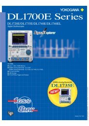
Waveform <strong>Measuring</strong> <strong>Instruments</strong><br />
Digital Oscilloscopes<br />
DL1720E/DL1735E<br />
DL1740E/DL1740EL<br />
http://www.yokogawa.com/tm/DL1700E/<br />
Waveform<br />
<strong>Measuring</strong><br />
<strong>Instruments</strong><br />
These Compact, Lightweight Models Offer High-speed<br />
Sampling and Long Memory<br />
Overview<br />
This series has an A4 sized footprint, is compact, and<br />
space-saving and with 350 MHz or 500 MHz bandwidth<br />
and Max. 8 MW memory.<br />
Features<br />
DL1740EL<br />
DL1735E<br />
Basic Specifi cations<br />
DL1740E<br />
DL1720E<br />
Input channels 4 (701725, 701730, 701740) 2 (701715)<br />
Voltage axis sensitivity setting range<br />
For 1 MΩ input: 2 mV/div to 10 V/div (steps of 1, 2, or 5)<br />
For 50 Ω input: 2 mV/div to 1 V/div (steps of 1, 2, or 5)<br />
Frequency characteristics<br />
For 1 MΩ input (using passive probe model 700988;<br />
spec i fi ed at probe tip): 10 V/div to 10 mV/div: DC to<br />
400 MHz (500 MHz * ), (DC to 350 MHz, 701725)<br />
*: When using Miniature passive probe model 701941;<br />
spec i fi ed at probe tip.<br />
A/D conversion resolution<br />
8 bits (24 LSB/div)<br />
Maximum sampling rate<br />
1 GS/s<br />
Maximum record length<br />
701715: 1 MW/CH<br />
701725, 701730: 2 MW/CH<br />
701740: 8 MW/CH<br />
DC accuracy ±(1.5% of 8 div + offset voltage accuracy)<br />
Time axis setting range<br />
1 ns/div to 50 s/div (for record length of 10 kW or great er)<br />
Display 6.4-inch color TFT liquid crystal display<br />
Built-in printer (optional)<br />
Paper width: 112 mm<br />
Computer interface<br />
GP-IB, USB-PC connector (USB Rev 1.1 compliant),<br />
Ethernet (100BASE-TX/10BASE-T com pli ant, optional)<br />
Other options: I 2 C + SPI bus analysis function, probe power<br />
External dimensions<br />
220 (W) × 265.8 (H) × 264.1 (D) mm<br />
Weight Approx. 5.5 kg (with all options)<br />
• Maximum sampling rate<br />
1 GS/s: Real-time sampling<br />
100 GS/s: Repetitive sampling<br />
• 500MHz analog bandwidth (DL1735E : 350 MHz)<br />
• Maximum record length<br />
DL1740EL: 8 Mwords<br />
DL1740E, DL1735E: 2 Mwords<br />
DL1720E: 1 Mwords<br />
• HDTV trigger<br />
• I 2 C and SPI bus trigger and analysis (optional)<br />
• USB storage and USB peripherals<br />
Supports USB memory devices (fl ash memory, hard disk drive, MO<br />
drive, etc.)<br />
Supports a USB mouse, key board, or printer<br />
• Ethernet function (optional)<br />
Web server, FTP server, and network printing<br />
• PC card interface (Type II)<br />
(or select fl oppy disk for removable media type)<br />
• Built-In printer (optional)<br />
Model Number and Suffi x Codes<br />
Model Suffix Code Description<br />
701715<br />
DL1720E digital oscilloscope with 2 ch input, 500<br />
MHz analog bandwidth and maximum 1 MW memory<br />
701725<br />
DL1735E digital oscilloscope with 4 ch input, 350<br />
MHz analog bandwidth and maximum 2 MW memory<br />
701730<br />
701740<br />
DL1740E digital oscilloscope with 4 ch input, 500<br />
MHz analog bandwidth and maximum 2 MW memory<br />
DL1740EL digital oscilloscope with 4 ch input, 500<br />
MHz analog bandwidth and maximum 8 MW memory<br />
Power cable<br />
Internal<br />
storage drive<br />
Options<br />
-D<br />
-F<br />
-Q<br />
-R<br />
-H<br />
-J1<br />
-J3<br />
/B5<br />
/P2<br />
/P4<br />
/C10<br />
/F5<br />
/EX2<br />
/EX4<br />
UL and CSA standard<br />
VDE standard<br />
BS standard<br />
AS standard<br />
GB standard<br />
Floppy disk drive 1<br />
PC card interface (type II) 1<br />
Built-in printer<br />
Probe power for model 701715 2<br />
Probe power for models 701725, 701730 and 701740 2<br />
Ethernet interface<br />
I 2 C + SPI bus analysis function 3<br />
Attach two 701941 probes 4<br />
Attach four 701941 probes 5<br />
The instrument comes standard with passive probes (700988). Four probes are included with the<br />
701725, 701730 and 701740, and two probes are included with the 701715.<br />
1. One or the other must be selected.<br />
2. Select /P2 for model 701715, or /P4 for models 701725, 701730 and 701740.<br />
3. Option for models 701725, 701730 and 701740 only.<br />
4. Option for model 701715 only. The 700988 probes are not included when this option is<br />
specified.<br />
5. Option for models 701725, 701730, 701740 only. The 700988 probes are not included when<br />
this option is specified.<br />
7
Waveform <strong>Measuring</strong> <strong>Instruments</strong><br />
Waveform<br />
<strong>Measuring</strong><br />
<strong>Instruments</strong><br />
Digital Oscilloscopes<br />
DL1620/DL1640/DL1640L<br />
http://www.yokogawa.com/tm/DL1600/<br />
Our Best-selling Models Support 3-mode Power Supplies and<br />
Weights just 3.9 kg<br />
Overview<br />
With a three-mode power supply (AC, 12 VDC and<br />
batterry) the DL1600 goes everywhere you need to<br />
make measurements.<br />
It also has serial bus (I 2 C, SPI, CAN), signal capturing,<br />
and protocol analysis functions.<br />
Features<br />
DL1640/DL1640L<br />
• CAN Bus signal analysis function (optional)<br />
• DC Power model + Battery box<br />
• I 2 C Bus analysis function (optional)<br />
• 4 channels 200 MS/s (DL1640/DL1640L)<br />
• 2 channels 200 MS/s (DL1620)<br />
• 200 MHz analog bandwidth<br />
• Maximum memory length:<br />
32 MW (DL1640L) and 8 MW (DL1640/DL1620)<br />
• 6.4-inch wide-angle-view TFT color liquid crystal display<br />
• Compact and lightweight (approx. 3.9 kg 10.8 lbs)<br />
• A4 size or smaller footprint<br />
• Internal storage media<br />
(select PC card, Zip ® drive, or Floppy drive)<br />
• USB compliant, USB storage Supported (optional)<br />
• Ethernet connectivity (optional)<br />
• Real-time digital fi ltering<br />
8<br />
DL1620<br />
DC power model + bat tery box<br />
Basic Specifi cations<br />
Input channels 4 (701610, 701620) 2 (701605)<br />
Sensitivity 2 mV/div to 10 V/div (in steps of 1, 2, or 5)<br />
DC accuracy 10 mV/div to 10 V/div: 1.5% of 8 div + offset voltage<br />
accuracy<br />
Frequency characteristics<br />
10 mV/div to 10 V/div: DC to 200 MHz<br />
Vertical resolution<br />
8 bits (24 LSB/div)<br />
Maximum sampling rate<br />
200 MS/s<br />
Maximum record length<br />
701605, 701610: 8 MW/ch<br />
701620: 32 MW/ch<br />
Sweep time 2 ns/div to 800 s/div (varies depends on memory length)<br />
Display 6.4-inch TFT color liquid crystal display<br />
Built-in printer (optional)<br />
112 mm paper width<br />
Communication interfaces<br />
Serial port (RS232), USB port (op tion al), USB-PC port<br />
(optional), GP-IB port (optional 1 ), Ethernet port (complies<br />
with 100BASE-TX and 10BASE-T; optional)<br />
Internal media drive<br />
Floppy drive, Zip ® drive, PC card drive<br />
Other options Built-in printer, Probe power, GP-IB + USB, Ethernet +<br />
USB, I 2 C bus signal analysis function, CAN bus signal<br />
analysis function.<br />
External dimensions<br />
220 (W) × 266 (H) × 224 (D) mm<br />
Weight Approx. 4.5 kg (10.8 lbs; with all options)<br />
Approx. 3.9 kg (8.6 lbs; without any options)<br />
Model Number and Suffi x Codes<br />
Model/Options Suffix code<br />
701605<br />
701610<br />
701620<br />
-AC<br />
-DC 1<br />
-D<br />
-F<br />
-Q<br />
Power cable<br />
-R<br />
-H<br />
-Y<br />
-J1<br />
Internal media drive -J2<br />
-J3<br />
/B5<br />
/P2<br />
/P4<br />
Other options<br />
/C1<br />
/C10<br />
/F5<br />
/F7<br />
Description<br />
DL1620 digital oscilloscope<br />
DL1640 digital oscilloscope<br />
DL1640L digital oscilloscope<br />
100–120 V & 220–240 V<br />
12 VDC<br />
UL/CSA standard<br />
VDE standard<br />
BS standard<br />
AS standard<br />
GB standard<br />
No power cable<br />
Floppy drive 2<br />
Zip ® drive 2<br />
PC card drive (Type II) 2<br />
Built-in printer<br />
Probe power for 701605<br />
Probe power for 701610 and 701620<br />
GP-IB + USB 3<br />
Ethernet + USB 3<br />
I 2 C bus signal analysis function 4<br />
CAN bus signal analysis function 5<br />
The main unit comes standard with four passive probes (700960) for 701610/701620<br />
and two passive probes for 701605.<br />
1 Select “-Y” for the DC power model.<br />
2 Choose one.<br />
3 Choose one.<br />
4 The I 2 C bus analysis function includes the SPI analysis function.<br />
I 2 C only be specified for model 701610 and 701620.<br />
5 The CAN bus analysis function inclncles the SPI bus analysis function.<br />
It can only be specified for model 701610 and 701620.<br />
Model/Options<br />
701680 6<br />
Power cable<br />
Suffix code<br />
-D<br />
-F<br />
-Q<br />
-R<br />
-H<br />
Description<br />
Battery box and charger<br />
UL/CSA standard<br />
VDE standard<br />
BS standard<br />
AS standard<br />
GB standard<br />
6 The Battery box comes standard with the cable for connecting to the main unit.
Waveform <strong>Measuring</strong> <strong>Instruments</strong><br />
ScopeCorder<br />
DL750/DL750P<br />
http://www.yokogawa.com/tm/DL750/ http://www.yokogawa.com/tm/DL750P/<br />
Waveform<br />
<strong>Measuring</strong><br />
<strong>Instruments</strong><br />
Innovative Solutions for Long-Term Recording to both Memory and Paper<br />
Overview<br />
ScopeCorder is a new measurement tool combining<br />
the func tions of an os cil lo scope for capturing<br />
instantaneous phenomena and a data recorder for<br />
mon i tor ing long-term trends<br />
Sample Rate<br />
DL750<br />
Seconds<br />
10 MS/s 100 seconds<br />
1 MS/s 600<br />
100 kS/s 9000<br />
10 kS/s 72000<br />
1 kS/s 864000<br />
200 S/s 2592000<br />
Basic Specifi cations<br />
Minutes<br />
1.67<br />
10 minutes<br />
150 minutes<br />
1200<br />
14400<br />
43200<br />
Hours<br />
0.028<br />
0.167<br />
2.5 hours<br />
20 hours<br />
240.0<br />
720.0<br />
DL750P<br />
Input<br />
Type Isolated plug-in module<br />
Slots 8 (16 channels)<br />
Logic inputs 16 (8 bits 2)<br />
Sweep time 500 ns to 3 days/div (10 div)<br />
Display 10.4-inch color TFT liquid crystal display<br />
Built-in printer<br />
Printing method Thermal line-dot printing<br />
Paper width 112 mm (DL750)<br />
210 mm (Effective print width 200mm) (DL750P)<br />
Communication interfaces<br />
GP-IB, USB peripheral equipment jacks (USB<br />
keyboards and USB printers), USB (complies with Rev.<br />
1.1, for connection to PC), Ethernet (complies with<br />
100BASE-TX and 10BASE-T; with /C10 option), serial<br />
(RS232), and SCSI<br />
Internal media drives<br />
Floppy drive, Zip ® drive (DL750), or PC card (choose<br />
one), and 40 GB hard drive (with /C8 option)<br />
External dimensions<br />
355 (W) 250 (H) 180 (D) mm (DL750)<br />
355 (W) 250 (H) 225 (D) mm (DL750P)<br />
Weight Approx. 6.6 kg (DL750), 8.0 kg (DL750P), (main unit<br />
with full options, including M3, C8, C10, and P4)<br />
Approx. 9 kg (DL750), 10.3 kg (DL750P), (main unit<br />
and eight 701250 modules)<br />
1 GW Memory for full-length display and instantaneous zooming (to user-spec i fi ed size)<br />
Maximum Recording Time<br />
Days<br />
0.001<br />
0.007<br />
0.10<br />
0.83 day<br />
10 days<br />
30 days<br />
Features<br />
• Standard high resolution A4 thermal printer (DL750P)<br />
• Effective print width is 200 mm (1600-dot resolution) (DL750P)<br />
• Compact body and isolated 16 analog channels, 8 slots and 16-bits log ic<br />
in put.<br />
• Eleven kind of plug-in modules offers high accuracy and low noise<br />
mea sure ment and also offer various measurement (Voltage/Current/<br />
Tem per a ture/Strain/Vibration/Frequency)<br />
• 1 GW large memory and 30 days observation.<br />
• 1 GW instantaneous display (GigaZoom Function)<br />
• Simultaneous high-speed and low-speed recording using Dual Capture<br />
• Cycle statistical calculation<br />
• Many Ethernet functions (Web server/FTP server/Email)<br />
• Various communication interfaces (USB/Ethernet/GPIB/RS232/SCSI)<br />
• PC card drive available<br />
• 40GB internal hard drive<br />
Model<br />
701210<br />
701230<br />
Power cable<br />
Default Help language<br />
Memory expansion<br />
Other specifications<br />
Model Number and Suffi x Codes<br />
-D<br />
-F<br />
-R<br />
-Q<br />
-H<br />
Internal media drive 2 -J1<br />
-J2<br />
-J3<br />
Suffix Code<br />
-HE<br />
-HJ<br />
-HC<br />
-HG<br />
-HF<br />
-HL<br />
-HK<br />
/M1<br />
/M2<br />
/M3<br />
/C8<br />
/C10<br />
/G2<br />
/G3<br />
/P4<br />
/DC<br />
Description<br />
“DL750 main unit (16 isolated channels, 8 slots + 16-<br />
bit logic) 1 112 mm width A6 thermal printer built-in”<br />
“DL750P main unit (16 isolated channels, 8 slots + 16-<br />
bit logic) 1 210 mm width A4 thermal printer built-in”<br />
UL/CSA standard<br />
VDE standard<br />
AS standard<br />
BS standard<br />
GB standard (Complied with CCC)<br />
Floppy drive<br />
Zip ® drive (available for the DL750 only) 3<br />
PC card drive<br />
English<br />
Japanese<br />
Chinese<br />
German<br />
French<br />
Italian<br />
Korean<br />
Memory expansion to 10 MW/CH 4<br />
Memory expansion to 25 MW/CH 4<br />
Memory expansion to 50 MW/CH 4<br />
Internal 40 GB hard drive (FAT32)<br />
Ethernet interface<br />
User-defined math function<br />
DSP channel function<br />
Probe power (4-output)<br />
DC 12V Power (10-18VDC) 3<br />
1. Plug-in modules are not included.<br />
2. Choose only one.<br />
3. Zip drive and DC12V power supply cannot be specified together with the DL750P.<br />
4. Cannot be specified together.<br />
9
Waveform <strong>Measuring</strong> <strong>Instruments</strong><br />
Waveform<br />
<strong>Measuring</strong><br />
<strong>Instruments</strong><br />
ScopeCorder LITE<br />
SL1400<br />
http://www.yokogawa.com/tm/SL1400/<br />
Easily & Quickly Saves Data to Memory and Paper<br />
Overview<br />
A plug-in module type chart recorder with a large<br />
built-in A4 sized high-resolution thermal printer<br />
SL1400<br />
Basic Specifi cations<br />
Input<br />
Type Isolated plug-in module<br />
Slots 8 (16 channels)<br />
Logic inputs 16 (8 bits × 2)<br />
Sweep time 100 us to 30 days<br />
Display 10.4-inch color TFT liquid crystal display<br />
Built-in printer<br />
Printing method Thermal line-dot printing<br />
Paper width 210 mm (Effective print width 200 mm)<br />
Communication interface<br />
GP-IB, USB peripheral equipment jacks<br />
(USB keyboards and USB printers), USB (compiles<br />
with Rev. 1.1, for con nec tion to PC), Ethernet (complies<br />
with 100 BASE-TX and 10 BASE-T; with /C10 option),<br />
serial (RS232), and SCSI<br />
Internal media drives<br />
PC card or Drive less (choose one), and 40GB hard drive<br />
(with /C8 option)<br />
External dimensions<br />
355(W) × 250(H) × 225(D) mm<br />
Weight Approx. 8.0 kg (main unit with full options, including<br />
C8, C10 and P4)<br />
Approx. 10.3 kg (main unit and eight 701250 modules)<br />
Features<br />
• Easy-to-operate<br />
• Standard high resolution A4 size thermal printer<br />
•Effective print width is 200 mm (1600-dot resolution)<br />
• Compact body and isolated 16 analog channels, 8 slots and 16-bits logic<br />
in put<br />
• Eleven kinds of plug-in modules offers high accuracy and low<br />
noise measurement and also offer various mea sure ment,<br />
Voltage/ Current/Tem per a ture/Strain/Vibration/Fre quen cy<br />
• 50MW large memory and 30 days observation<br />
• Cycle statistical calculation<br />
• Many Ethernet functions (Web server/FTP server/E-mail)<br />
•Various communication interface USB/Ethernet/GP-IB/RS-232/ SCSI<br />
• PC card drive is available<br />
• 40 GB internal hard drive<br />
• USB storage function is available<br />
Model<br />
701240<br />
Power cable 2<br />
Internal media<br />
drive 2<br />
Language 2<br />
Other specifications<br />
1. Plug-in modules are not included.<br />
2. Choose only one.<br />
Model Number and Suffi x Codes<br />
Suffix Code<br />
-D<br />
-F<br />
-R<br />
-Q<br />
-H<br />
-J0<br />
-J3<br />
-HE<br />
-HJ<br />
-HC<br />
-HG<br />
-HF<br />
-HL<br />
-HK<br />
-HS<br />
/C8<br />
/C10<br />
/P4<br />
Description<br />
SL1400 main unit (16 isolated Channels, 8 slots + 16-bit logic) 1<br />
210 mm width A4 thermal printer built-in<br />
UL/ CSA standard<br />
VDE standard<br />
AS standard<br />
BS standard<br />
GB standard (Complied with CCC)<br />
non Drive<br />
PC card drive<br />
English, Panel in English<br />
Japanese, Panel in Japanese<br />
Chinese, Panel in English<br />
German, Panel in English<br />
French, Panel in English<br />
Italian, Panel in English<br />
Korean, Panel in English<br />
Spanish, Panel in English<br />
Internal 40 GB hard drive (FAT32)<br />
Ethernet option<br />
Probe power (4-output)<br />
10<br />
Module Selection<br />
701250<br />
701251<br />
701255<br />
701260<br />
701261<br />
701262<br />
701265<br />
701270<br />
701271<br />
701275<br />
701280<br />
* Above plug-in modules can be used among all ScopeCorder series.<br />
Model<br />
701250<br />
701251<br />
701255<br />
701260<br />
701261<br />
701262<br />
701265<br />
701270<br />
701271<br />
701275<br />
701280<br />
Description<br />
High-speed 10 MS/s 12-bit Isolation module (2 CH)<br />
High-speed 1 MS/s 16-bit Isolation module (2 CH)<br />
High-speed 10 MS/s 12-bit non-Isolation module (2 CH)<br />
High-voltage 100 kS/s 16-bit Isolation module (2 CH, with RMS)<br />
Universal module (2 CH)<br />
Universal module (with anti-aliasing filter, 2 CH)<br />
Temperature/high-precision voltage module (2 CH)<br />
Strain module (NDIS, 2 CH)<br />
Strain module (DSUB, Shunt-CAL, 2 CH)<br />
Accelaration module (with anti-aliasing filter, 2 CH)<br />
Frequency module (2 CH)<br />
Probes not included with any modules.<br />
Plug-in Module Model Numbers
Waveform <strong>Measuring</strong> <strong>Instruments</strong><br />
DL9240/DL9240L<br />
Accessory<br />
USB2.0 Compliance Test Solution<br />
busXplorer TM -USB<br />
http://www.yokogawa.com/tm/busXplorer-USB/<br />
Waveform<br />
<strong>Measuring</strong><br />
<strong>Instruments</strong><br />
The USB 2.0 compliance test solution *1<br />
busXplorer TM -USB takes ad van tage of the wide<br />
va ri ety of DL9000 trig ger and analysis func tions<br />
to offer a system for car ry ing out high ly<br />
au to mat ed USB com pli ance tests. In ad di tion to<br />
fa cil i tat ing execution of the var i ous tests from a<br />
PC via Ethernet, the new ly de vel oped test<br />
soft ware displays detailed test pro ce dures<br />
including the wir ing method. This al lows even<br />
in ex pe ri enced op er a tors to easily perform the<br />
tests.<br />
*1) busXplorer TM -USB comprises a test fi x ture and test soft ware.<br />
USB2.0 Compliance Test Solution Equipments<br />
• 701312/701313 DL9240/DL9240L<br />
• 701985<br />
USB Compliance Test Fixture & Software<br />
• 701923<br />
PBD2000 2GHz BW differential probe<br />
• 701913<br />
PBA2000 2.5GHz BW active probe<br />
• 701933<br />
50MHz BW current probe<br />
*The equipment that is required varies depending on the test. Please contact us for details.<br />
Detailed anal y ses of sig nal wave forms can be<br />
per formed by us ing the sys tem in con junc tion with<br />
the Xviewer Wave form Analysis Tool (sold<br />
sep a rate ly).<br />
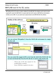
DL Series Accessories<br />
Soft ware<br />
X viewer/MATLAB tool kit<br />
http://www.yokogawa.com/tm/product/tm-product.htm<br />
View Waveform Data on Your PC<br />
Plug-in for MATLAB software<br />
701992<br />
Xviewer<br />
Xviewer is a PC software application designed to work with <strong>Yokogawa</strong>’s DL Series and the<br />
DL750 Series ScopeCorders. Xviewer allows you to display DL-acquired waveform data<br />
(us ing the “Viewer” function), perform fi le transfers, and con trol DL Series from a PC.<br />
You can download a trial version of Xviewer from <strong>Yokogawa</strong>’s web site at:<br />
http://www.yokogawa.com/tm/701992/<br />
701991<br />
MATLAB tool kit<br />
The MATLAB tool kit for the DL Series is a plug-in for MATALAB software. The toolkit<br />
can be used to control supported instruments using MATLAB or to acquire data from the<br />
in stru ments to use in MATLAB via a communication interface (GP-IB, USB, Ethernet).<br />
You can download a trial version of MATLAB tool kit from <strong>Yokogawa</strong>’s web site at: http://<br />
www.yokogawa.com/tm/701991/<br />
In addition to the above, various kinds of accessory software, free software, LabVIEW drivers, and LabWindows/CVI drivers, can be downloaded from the following web site.<br />
http://www.yokogawa.com/tm/tm-softdownload.htm<br />
11
Waveform <strong>Measuring</strong> <strong>Instruments</strong><br />
Waveform<br />
<strong>Measuring</strong><br />
<strong>Instruments</strong><br />
Waveform <strong>Measuring</strong><br />
Product<br />
PB500<br />
(500 MHz passive probe)<br />
DL Series Accessories List<br />
Part No.<br />
701943<br />
500 MHz BW, 10:1, 1.5 meters<br />
Description<br />
DL9700<br />
DL9000<br />
DL7400<br />
DL1600<br />
DL1700E<br />
PBA2500<br />
(2.5 GHz active probe)<br />
701913<br />
2.5 GHz BW, 10:1, 1.2 meters<br />
PBA1500<br />
(1.5 GHz active probe)<br />
701914<br />
1.5 GHz BW, 10:1, 1.2 meters<br />
PBA1000<br />
(1.0 GHz active probe)<br />
701912<br />
1.0 GHz BW, 10:1, 1.2 meters<br />
PBD 2000<br />
(2 GHz differential probe)<br />
701923<br />
2 GHz BW, 10:1, Max. differential input voltage: ±5 V, 1.2 meters<br />
PBL5000<br />
(5 GHz low<br />
capacitance probe)<br />
400 MHz passive probe<br />
200 MHz passive probe<br />
500 MHz Miniature<br />
passive probe<br />
350 MHz Miniature<br />
passive probe<br />
701974<br />
700988<br />
700960<br />
701941<br />
701942<br />
5 GHz BW, 10:1, 20:1, 0.95 meters<br />
400 MHz BW (10:1)<br />
<strong>All</strong>ows the division ratio to be switched between 10:1 and 1:1.<br />
1.5meters<br />
200 MHz BW (10:1)<br />
<strong>All</strong>ows the division ratio to be switched between 10:1 and 1:1.<br />
1.5meters<br />
DC to 500 MHz, 10:1, 1.2 meters<br />
DC to 350 MHz, 10:1, 3.0 meters<br />
100:1<br />
High voltage probe<br />
701944<br />
400 MHz BW, 100:1, 1.2 meters<br />
100:1<br />
High voltage probe<br />
701945<br />
250 MHz BW, 100:1, 3.0 meters<br />
900 MHz FET Probe<br />
700939<br />
DC to 900 MHz, Input impedance 1.8 pF<br />
Logic probe<br />
Logic probe<br />
100 MHz<br />
differential probe<br />
200 MHz<br />
differential probe<br />
15 MHz<br />
differential probe<br />
100 MHz<br />
differential probe<br />
500 MHz<br />
differential probe<br />
Deskew signal source<br />
Current probe<br />
Current probe<br />
Current probe<br />
701980<br />
701981<br />
701921<br />
701922<br />
700925<br />
700924<br />
701920<br />
701935<br />
701933<br />
701930<br />
701931<br />
Input impedance: 1 MΩ<br />
Max. toggle frequency: 100 MHz<br />
Input impedance: 10 KΩ<br />
Max. toggle frequency: 250 MHz<br />
DC~100 MHz, 10:1, 100:1,<br />
Max. differential input voltage: ±70 V (10:1), ±700 V (100:1)<br />
DC~200 MHz, 10:1,<br />
Max. differential input voltage: ±20 V<br />
DC~15 MHz, 10:1, 100:1,<br />
Max. differential input voltage: ±500 V (100:1), ±50 V (10:1)<br />
DC~100 MHz, 100:1, 1000:1,<br />
Max. differential input voltage: ±1400 V (1000:1), ±350 V (100:1)<br />
DC~500 MHz, 10:1,<br />
Max. differential input voltage: ±12 V<br />
Output voltage: Approx. 0-5 V<br />
Output current: Approx. –100 to 0 mA<br />
DC to 50 MHz<br />
30 Arms<br />
DC to 10 MHz<br />
150 Arms<br />
DC to 2 MHz, 500 Arms<br />
Current probe<br />
701932<br />
DC to 100 MHz, 30 Arms<br />
Probe power supply<br />
701934<br />
Large current output, external probe power supply (4 outputs)<br />
50 Ω terminator<br />
Probe stand<br />
700976<br />
701919<br />
Used to connect an oscilloscope having a 1 MΩ input to an instrument having<br />
a 50 Ω output.<br />
Diameter of attachable probe : ø8 to 13mm<br />
Weight : Approx. 1.5 kg<br />
12
Waveform <strong>Measuring</strong> <strong>Instruments</strong><br />
Waveform <strong>Measuring</strong><br />
ScopeCorder Series Accessories List<br />
Waveform<br />
<strong>Measuring</strong><br />
<strong>Instruments</strong><br />
Product<br />
15 MHz band<br />
differential probe<br />
Part No.<br />
700925<br />
Description<br />
A probe designed for digital oscilloscopes to transform its single-ended<br />
input to a differential input. ±500 V (DC + AC peak)<br />
100 MHz band<br />
differential probe<br />
Current probe<br />
30 Arms<br />
Current probe<br />
150 Arms<br />
700924<br />
701933<br />
701930<br />
A probe lets you make wide-band differential input measurements.<br />
Just connect the probe to the input of a single-end input digital oscilloscope.<br />
±1400 V (DC + AC peak) or 1000 Vrms<br />
Bandwidth DC up to 50 MHz. Can be directly connected to an oscilloscope<br />
with 1 MΩ input impedance.<br />
Bandwidth DC up to 10 MHz. Can be directly connected to an oscilloscope<br />
with 1 MΩ input impedance.<br />
Current probe<br />
500 Arms<br />
701931<br />
DC to 2 MHz, 500 Arms<br />
Current probe<br />
30 Arms<br />
701932<br />
DC to 100 MHz bandwidth, 30 Arms<br />
Probe power supply<br />
701934<br />
Large current output, external probe power supply (4 outputs)<br />
Isolation probe<br />
700929<br />
A 10:1 probe designed for use with isolated modules<br />
1:1 BNC safety adapter lead<br />
(with combination with followings)<br />
701901<br />
1000 Vrms-CAT II for 701250, 701251, 701260 (10:1)<br />
Safety mini clip<br />
(hook type)<br />
701959<br />
1000 Vrms-CAT II (2 per set)<br />
Large alligator clip<br />
(dolphin type)<br />
701954<br />
1000 Vrms-CAT II (2 per set)<br />
Passive probe<br />
for DL750/SL1400 (10:1)<br />
701940<br />
Non-isolated 600 Vpk (701255) 42 V or less (others)<br />
BNC cable<br />
366926<br />
A 1 m long BNC-alligator clip cable.<br />
Accessories Combinations<br />
High-speed<br />
10MS/s<br />
12-bit Isolation<br />
Module<br />
701250<br />
Isolation Probe<br />
700929<br />
Large <strong>All</strong>igator<br />
Clips (Dolphin<br />
Type)<br />
701954<br />
Current Probe<br />
30Arms DC<br />
-50MHz<br />
701933<br />
/P4,<br />
Probe Power<br />
4-output<br />
(option)<br />
High-speed 10MS/s<br />
12-bit Nonisolation<br />
Module<br />
701255<br />
Passive Probe for<br />
SL1400/DL750<br />
701940<br />
BNC cable<br />
1m: 366924<br />
2m: 366925<br />
Carrying Case<br />
701967<br />
High-speed<br />
Logic Probe<br />
700986<br />
High-speed<br />
1MS/s 16-bit<br />
Isolation Module<br />
701251<br />
High-voltage<br />
100kS/s 16-bit<br />
Isolation Module<br />
701260<br />
1:1 BNC<br />
Safety Adaptor<br />
Lead<br />
700901<br />
Isolated Leads<br />
758917<br />
Safety<br />
Mini Clips<br />
(Hook Type)<br />
701959<br />
<strong>All</strong>igator<br />
Adapters<br />
758922<br />
<strong>All</strong>igator<br />
Adapters<br />
758929<br />
Current Probe<br />
150Arms DC<br />
-10MHz<br />
701930<br />
Current Probe<br />
500Arms DC<br />
-2MHz<br />
701931<br />
Differential Probe<br />
1000Vrms<br />
700924<br />
Probe Power<br />
4-output<br />
701934<br />
Acceleration/Voltage<br />
Mod ule (with AAF)<br />
701275<br />
Strain Module (NDIS)<br />
701270<br />
Strain Module<br />
(DSUB Shunt-CAL)<br />
701271<br />
BNC-alligator<br />
cable<br />
366926<br />
Bridge Head (NDIS)<br />
120 Ohm: 701955<br />
350 Ohm: 701956<br />
Bridge Head<br />
(DSUB, Shunt-Cal)<br />
120 Ohm: 701957<br />
350 Ohm: 701958<br />
Logic Input<br />
Terminals<br />
Isolated Logic<br />
Probe<br />
700987<br />
Isolated Logic<br />
Measurement<br />
Leads<br />
758917<br />
<strong>All</strong>igator Adapters<br />
758922<br />
Universal Module<br />
701261<br />
<strong>All</strong>igator Adapters<br />
758929<br />
Frequency<br />
Module<br />
701280<br />
Safety BNC<br />
Cable<br />
1m : 701902<br />
3m : 701903<br />
Fork Terminal<br />
Adapters<br />
758921<br />
Universal Module<br />
(with AAF)<br />
701262<br />
Temperature/Highprecision<br />
Voltage Module<br />
701265<br />
1:1 Banana-alligator Cable<br />
366961<br />
Shunt Resister for 4-20mA<br />
Measurement<br />
250 Ohm ± 0.1% : 438920<br />
100 Ohm ± 0.1% : 438921<br />
10 Ohm ± 0.1% : 438922<br />
Logic Probe<br />
(TTL level/<br />
Contact Input)<br />
1m: 702911<br />
3m: 702912<br />
13
Power <strong>Measuring</strong> <strong>Instruments</strong><br />
Power <strong>Measuring</strong><br />
<strong>Instruments</strong><br />
Selection <strong>Guide</strong><br />
http://www.yokogawa.com/tm/wtpz/tm-wtpz.htm<br />
Power<br />
<strong>Measuring</strong><br />
<strong>Instruments</strong><br />
Power <strong>Measuring</strong> <strong>Instruments</strong><br />
<strong>Yokogawa</strong>’s WT Series Power Meters and PZ4000 Power Analyzer:<br />
Advanced Technology and High Reliability for a Wide Range of Power Measurement Solutions<br />
WT Series<br />
Models<br />
WT3000<br />
WT2000<br />
WT1600<br />
WT210/WT230<br />
Items<br />
Features<br />
With basic power accuracy of<br />
±0.02% of reading, DC and 0.1 Hz-<br />
1 MHz measurement bandwidths,<br />
and up to four input elements, the<br />
WT3000 provides higher-accuracy<br />
measurement of inverter I/O<br />
efficiency.<br />
Total harmonic measurement and<br />
analysis function<br />
Voltage fluctuation/flicker<br />
measurement function<br />
Higher power accuracy<br />
Up to six Input elements in one<br />
instrument (3 phase power input<br />
from two systems in one unit)<br />
6.4-Inch TFT Color LCD<br />
Wide voltage and current input<br />
range<br />
Entry class model<br />
Compact design (half-rack size) and<br />
superior cast performance<br />
5 mA range for very low current<br />
measurements (model WT210 only)<br />
Input elements<br />
Basic power accuracy (50/60 Hz)<br />
Power measurement frequency range<br />
Input voltage range<br />
Input current range<br />
Measurement parameters<br />
Display<br />
External dimensions (mm) (W × H × D)<br />
Weight (kg)<br />
1 to 4<br />
0.02% of rdg + 0.04% of rng<br />
DC, 0.1 Hz to 1 MHz<br />
15/30/60/100/<br />
150/300/600/1000 V<br />
Direct input: 0.5/1/2/5/10/20/30 A or<br />
5 m/10 m/20 m/50 m/100 m/200 m/<br />
500 m/1/2 A<br />
External input:<br />
50/100/200/500 mV/1/2/5/10 V<br />
Voltage, Current, Active power,<br />
Reactive power, Apparent power,<br />
Power factor, Phase angle, Peak<br />
voltage, Peak current, Voltage<br />
Frequency, Current Frequency,<br />
Active power integration, Apparent<br />
power integration, Reative power<br />
integration, Current integration,<br />
Corrected power, Crest factor,<br />
Efficiency, Harmonic analysis<br />
8.4-inch TFT color LCD<br />
426 × 177 × 459<br />
15<br />
1 to 3<br />
0.04% of rdg + 0.04% of rng<br />
DC, 2 Hz to 300 kHz<br />
10/15/30/60/100/<br />
150/300/600 V<br />
Direct input: 1/2/5/10/20/30 A<br />
External input: 50 m/100 m/200 mV<br />
Voltage, Current, Active power,<br />
Reactive power, Apparent power,<br />
Power factor, Phase angle, Peak<br />
voltage, Peak current, Voltage<br />
Frequency, Current Frequency,<br />
Active power integration, Current<br />
integration, Efficiency, Harmonic<br />
analysis, Flicker measurement<br />
7-segment LED, 4 displays<br />
426 × 132 × 400<br />
13<br />
1 to 6<br />
0.1% of rdg + 0.05% of rng<br />
DC, 0.5 Hz to 1 MHz<br />
1.5/3/6/10/15/30/60/<br />
100/150/300/600/1000 V<br />
Direct input:<br />
10 m/20 m/50 m/100 m/200 m/<br />
500 m/1/2/5 A or 1/2/5/10/20/50 A<br />
External input:<br />
50 m/100 m/250 m/500 m/<br />
1/2.5/5/10 V<br />
Voltage, Current, Active power,<br />
Apparent power, Reactive power,<br />
Power factor, Phase angle, Peak<br />
voltage, Peak current, Voltage<br />
Frequency, Current Frequency,<br />
Active power integration, Current<br />
integration, Crest factor, Form<br />
factor, Impedance, Resistance,<br />
Reactance, Corrected Power,<br />
Harmonic analysis<br />
6.4-inch TFT color LCD<br />
426 × 177 × 400<br />
15<br />
1 (WT210), 2 or 3 (WT230)<br />
0.1% of rdg + 0.1% of rng<br />
DC, 0.5 Hz to 100 kHz<br />
15/30/60/150/300/600 V<br />
Direct input:<br />
5 m /10 m/20 m/50 m/100 m/200 m/<br />
500 m/1/2/5/10/20 A (WT210)<br />
Direct input:<br />
500 m/1/2/5/10/20 A (WT230)<br />
External input (option):<br />
2.5/5/10 V or 50 m/100 m/200 mV<br />
Voltage, Current, Active power,<br />
Reactive power, Apparent power,<br />
Power factor, Phase angle, Peak<br />
voltage, Peak current, Voltage<br />
Frequency, Current Frequency,<br />
Active power integration, Current<br />
integration, Harmonic analysis<br />
7-segment LED, 3 displays<br />
213 × 88 × 379 (WT210)<br />
213 × 132 × 379 (WT230)<br />
3 (WT210), 5 (WT230)<br />
PZ4000 Power Analyzer<br />
Models<br />
PZ4000<br />
Items<br />
Features<br />
A power analyzer that displays<br />
measured waveforms<br />
Wide bandwidth, high-precision<br />
measurements<br />
A power analyzer capable of<br />
dynamically capturing load<br />
fluctuations<br />
Graphical power analysis<br />
Input elements<br />
Basic power accuracy (50/60 Hz)<br />
Power measurement frequency range<br />
Input voltage range<br />
Input current range<br />
1 to 4 or 1 to 3 + Sensor input<br />
0.1% of rdg + 0.025% of rng<br />
DC, 0.1 Hz to 1 MHz<br />
30/60/120/200/300/600/<br />
1200/2000 V peak<br />
Direct input 5 A: (253751, 253752)<br />
0.1/0.2/0.4/1/2/4/10 Apeak<br />
Direct input 20 A: 1/2/4/10/20/<br />
40/100 Apeak (253752 only)<br />
External input:<br />
100/200/400/1000 mVpeak<br />
Measurement parameters<br />
Voltage, Current, Active power,<br />
Apparent power, Reactive power,<br />
Power factor, Phase angle, Peak<br />
voltage, Peak current, Voltage<br />
Frequency, Current Frequency,<br />
Crest factor, Form factor,<br />
Impedance, Resistance,<br />
Reactance, Efficiency, Corrected<br />
Power, Harmonic analysis<br />
Display<br />
External dimensions (mm) (W × H × D)<br />
6.4-inch TFT color LCD<br />
426 × 177 × 450<br />
Weight (kg)<br />
15<br />
14<br />
*About CW series Clamp-on Power Meters, please refer to the page 63.
Power <strong>Measuring</strong> <strong>Instruments</strong><br />
Precision Power Analyzer<br />
WT3000<br />
http://www.yokogawa.com/tm/WT3000/<br />
High-end Power Analyzer with Best-in-Class Precision ±0.02%<br />
of Reading and High Stability<br />
Power<br />
<strong>Measuring</strong><br />
<strong>Instruments</strong><br />
Overview<br />
WT3000<br />
For three-phase power metering, the WT3000 Precision<br />
Power Analyzer provides a basic power accuracy of<br />
±0.02% of reading. It also offers bandwidth for DC or<br />
0.1 Hz–1 MHz and accepts up to 4 input elements,<br />
facilitating high pre ci sion effi ciency measurements<br />
through simultaneous measurement during I/O of<br />
in vert ers and other items under test.<br />
This, coupled with the ability to perform normal pow er<br />
and harmonic measurements simultaneously, means<br />
that the WT3000 can offer higher accuracy in evaluation<br />
of instruments and higher effi ciency.<br />
Model Number and Suffi x Codes<br />
Model<br />
760301<br />
Suffix Codes<br />
Description<br />
WT3000 1 input element model<br />
WT3000 2 input elements model<br />
WT3000 3 input elements model<br />
WT3000 4 input elements model<br />
760302<br />
760303<br />
760304<br />
Element number<br />
Version<br />
Power cord<br />
Options<br />
-01<br />
-02<br />
-03<br />
-04<br />
-10<br />
-20<br />
-30<br />
-40<br />
-SV<br />
-MV<br />
-D<br />
-F<br />
-R<br />
-Q<br />
-H<br />
/G6<br />
/B5<br />
/DT<br />
/FQ<br />
/DA<br />
/V1<br />
/C2 Select<br />
/C12 one<br />
/C5<br />
/C7<br />
/CC<br />
/FL<br />
30A input element<br />
2A input element<br />
for 760301 model<br />
for 760302 model<br />
for 760303 model<br />
for 760304 model<br />
for 760301 model<br />
for 760302 model<br />
for 760303 model<br />
for 760304 model<br />
Standard Version<br />
Motor Version<br />
UL/CSA standard<br />
VDE standard<br />
SAA standard<br />
BS standard<br />
GB standard<br />
Advanced Computation<br />
(IEC standard testing*, harmonic, FFT, Waveform computation)<br />
Built-in Printer<br />
Delta Calculation<br />
Add-on Frequency Measurement<br />
20ch D/A output<br />
VGA Output<br />
Serial (RS-232) Interface<br />
USB port (PC)<br />
USB port (Peripheral)<br />
Ethernet function<br />
Cycle by Cycle<br />
Voltage Fluctuation, Flicker<br />
* requires 761922 software<br />
Note: Mixing of the 30 A and 2 A input elements is not supported, whether purchasing a new unit or<br />
reworking an existing one. Also, the unit cannot be modified to change the current range.<br />
Adding input modules after initial product delivery will require rework at the factory.<br />
Please choose your models and configurations carefully, and inquire with your sales<br />
representative if you have any questions.<br />
Features<br />
• High accuracy and wide frequency range<br />
• Up to 4 input elements<br />
•Low power factor error<br />
•Effective input range: 1% to 130%<br />
• Simultaneously measurement with 2 units<br />
• Data update rate: 50 ms to 20 sec<br />
•Variety of display formats:<br />
Numeric, Waveform, Bar graph, Vector, Trend, MATH, FFT, CC<br />
• IEC harmonic measurement in combination with software (761922)<br />
• IEC Flicker measurement (/FL option)<br />
• Storage function (approximately 30 MB internal memory )<br />
• Motor effi ciency and total effi ciency measurement (Motor version)<br />
Basic Specifi cations<br />
• Measurement voltage range:<br />
15/30/60/100 /150/300/600/1000 V (for crest factor 3)<br />
7.5/15/30/50/75/150/300/500 V (for crest factor 6)<br />
• Measurement current range:<br />
Direct input (30 A input element)<br />
500 mA/1/2 /5/10/20/30 A<br />
Direct input (2 A input element)<br />
5 m/10 m/20 m/50 m/100 m/200 m/500 m/1/2 A<br />
External sensor input<br />
50/100 /200/500 mV/1/2/5/10 V<br />
• Frequency range:<br />
DC, 0.1 Hz to 1 MHz<br />
• Accuracy (45 to 66 Hz):*greater than or equal to 500 mA range<br />
Voltage/current ±(0.01% of reading + 0.03% of range)<br />
Power ±(0.02% of reading + 0.04% of range)<br />
• Infl uence of power factor (λ):<br />
When λ = 0<br />
Apparent power reading × 0.03% in the 45 to 66 Hz range<br />
• External dimensions:<br />
Approx. 426 (W) × 177 (H) × 459 (D) mm<br />
•Weight: Approx. 15 kg<br />
(including main unit, 4 input elements, and options)<br />
15
Power <strong>Measuring</strong> <strong>Instruments</strong><br />
Power<br />
<strong>Measuring</strong><br />
<strong>Instruments</strong><br />
Digital Power Meters<br />
WT1600<br />
http://www.yokogawa.com/tm/WT1600/<br />
A High-Precision, Wide Frequency Range, Digital Power Meter<br />
with up to Six Input Elements<br />
WT1600<br />
Overview<br />
The WT1600 is a power meter designed to measure<br />
extremely small currents in energy-saving equipments,<br />
as well as large cur rents for eval u at ing large-sized<br />
loads. The WT1600 works with volt ag es rang ing from<br />
1.5 V up to 1000 V and supports a wide range of<br />
applications. A WT1600 can measure I/O signals on<br />
inverters, because it can accept signal inputs for up to<br />
six phases<br />
Model Suffix codes Description<br />
760101 WT1600 digital power meter main unit<br />
Element Number<br />
Element types and<br />
quantities<br />
The numbers in the<br />
“Descrip-tion” column<br />
have the following<br />
meanings.<br />
50: 50 A input element<br />
5: 5 A input element<br />
Blank: No element<br />
Elements are inserted<br />
in the order shown<br />
starting on the left side<br />
on the back.<br />
Communication<br />
functions<br />
Model Number and Suffi x Codes<br />
1 2 3 4 5 6<br />
-01 50<br />
-02 50 50<br />
-03 50 50 50<br />
-04 50 50 50 50<br />
-05 50 50 50 50 50<br />
-06 50 50 50 50 50 50<br />
-10 5<br />
-11 5 50<br />
-12 5 50 50<br />
-13 5 50 50 50<br />
-14 5 50 50 50 50<br />
-15 5 50 50 50 50 50<br />
-20 5 5<br />
-21 5 5 50<br />
-22 5 5 50 50<br />
-23 5 5 50 50 50<br />
-24 5 5 50 50 50 50<br />
-30 5 5 5<br />
-31 5 5 5 50<br />
-32 5 5 5 50 50<br />
-33 5 5 5 50 50 50<br />
-40 5 5 5 5<br />
-41 5 5 5 5 50<br />
-42 5 5 5 5 50 50<br />
-50 5 5 5 5 5<br />
-51 5 5 5 5 5 50<br />
-60 5 5 5 5 5 5<br />
-C1 GP-IB<br />
-C2 Serial (RS-232)<br />
Power cord -D UL/CSA Standard<br />
-F VDE Standard<br />
-R SAA Standard<br />
-Q BS Standard<br />
-H GB Standard<br />
Option specifications /B5 Internal printer<br />
/C7 SCSI interface<br />
/C10 Ethernet, HDD, SCSI<br />
/DA 30-channel DA output<br />
/MTR Motor evaluation function<br />
Features<br />
• Up to six input elements in one instrument (3 phase power input from<br />
two systems in one unit)<br />
•Wide frequency range<br />
•Wide current input range: 10 mA to 5 A or 1 A to 50 A<br />
•Wide voltage input range: 1.5 V to 1000 V<br />
• 50 ms data storing interval<br />
• Standard integration and harmonic measurement functions<br />
•Variety of display formats:<br />
Numeric, Waveform, Bar graph, Vector, Trend<br />
• Standard external current sensor input for use with current clamps<br />
• Motor evaluation function (optional)<br />
• 30ch D/A output (optional)<br />
• Built-in printer (optional)<br />
• Ethernet function (optional)<br />
Basic Specifi cations<br />
• Measurement voltage range<br />
1.5/3/6/10/15/30/60/100/150/300/600/1000 V<br />
(DC, 0.5 Hz to 1 MHz)<br />
• Measurement current input range (Direct in put)<br />
5 A input element<br />
10/20/50/100/200/500 mA, 1/2/5 A<br />
(DC, 0.5 Hz to 1 MHz)<br />
50 A input element<br />
1/2/5/10/20/50 A (DC, 0.5 Hz to 100 kHz)<br />
External sensor input (same for 5 A and 50 A input el e ments)<br />
50/100/250/500 mV, 1/2.5/5/10 V (DC, 0.5 Hz to 500 kHz)<br />
• Basic accuracy: (45 Hz ≤ f ≤ 66 Hz)<br />
Voltage/Current/Power:<br />
±(0.1% of rdg + 0.05% of rng)<br />
•Effective of power factor (at cos φ = 0)<br />
±0.15% of rng added<br />
• External dimensions:<br />
Approx. 426 (W) × 177 (H) × 400 (D) mm<br />
•Weight: Approx. 15 kg (with 6-input element)<br />
16<br />
* The WT1600 unit cannot be pur chased without any elements. Se lect an<br />
element type (5 A or 50 A) and quantity.<br />
Note: In order to add elements and options after the WT1600 has been<br />
delivered, the WT1600 must be mod i fi ed at the factory. Be aware of<br />
this in mak ing your prod uct selections. For further de tails, see<br />
<strong>Yokogawa</strong>’s home page or con tact our sales offi ce.
Power <strong>Measuring</strong> <strong>Instruments</strong><br />
Digital Power Meters<br />
WT210/WT230<br />
http://www.yokogawa.com/tm/WT210/<br />
Digital Sampling Power Meters with Superior Cost Per for mance<br />
Power<br />
<strong>Measuring</strong><br />
<strong>Instruments</strong><br />
WT210<br />
For standby low-power measurements and<br />
rated-power measurements.<br />
A single-phase model<br />
Overview<br />
The WT210 and WT230 are com pact, half-rack sized<br />
pow er meters. They are suited for a wide range of<br />
applications from low-frequency in stru ments to<br />
inverters, and offer improved basic accuracy and<br />
bandwidth. WT210 also has the same 5 mA range as<br />
WT200 al low ing mea sure ment of the ex treme ly small<br />
cur rents found in en er gy-saving designs and<br />
intermittent control devices.<br />
Features<br />
•Wiring Types and Model Numbers<br />
Wiring<br />
WT230<br />
For measurement applications from low-frequency<br />
equipment to high frequency inverters.<br />
A three-phase model<br />
Single-phase 2-wire<br />
Single-phase 3-wire<br />
Three-phase 3-wire (2 voltages, 2 currents)<br />
Three-phase 3-wire (3 voltages, 3 currents)<br />
Three-phase 4-wire<br />
Basic Specifi cations<br />
• Measurement voltage range<br />
Voltage: 15/30/60/150/300/600 V<br />
• Measurement current range<br />
Direct input:<br />
5 m/10 m/20 m/50 m/100 m/200 mA<br />
0.5/1/2/5/10/20 A (WT210),<br />
0.5/1/2/5/10/20 A (WT230)<br />
External Sensor input (optional):<br />
2.5/5/10 V or 50/100/200 mV<br />
• Frequency range:<br />
DC and 0.5 Hz to 100 kHz<br />
• Basic accuracy (45 Hz ≤ f ≤ 66 Hz)<br />
Voltage/current/power<br />
±(0.1% of rdg + 0.1% of rng)<br />
•Effect of power factor (at cos φ = 0)<br />
±0.2% of rng added<br />
• External dimensions:<br />
approx. 213 (W) × 88 (H) × 379 (D) mm (WT210)<br />
approx. 213 (W) × 132 (H) × 379 (D) mm (WT230)<br />
•Weight: approx. 3.0 kg (WT210)<br />
approx. 5.0 kg (WT230)<br />
Model<br />
760401<br />
–<br />
–<br />
–<br />
–<br />
760502<br />
–<br />
–<br />
760503<br />
• Maximum input with assured accuracy: 26 A<br />
• Compact design (half-rack size)<br />
•5 mA range for very low current measurements (model WT210 only)<br />
• Line fi lter function<br />
• High-speed data update (as fast as 10 readings per second)<br />
• Harmonic measurement function available (optional)<br />
• User calibration capability<br />
• Large-current measurement capability using external sensor input<br />
(optional)<br />
Model Number and Suffi x Codes<br />
Model number Suffix code<br />
Description<br />
760401<br />
WT210 single-input element model<br />
Power cord -D<br />
UL/CSA standard<br />
-F<br />
VDE standard<br />
-R<br />
AS standard<br />
-Q<br />
BS standard<br />
-H<br />
GB standard<br />
Options<br />
/C1<br />
GP-IB communication interface<br />
Select<br />
/C2<br />
Serial (RS-232-C) communication interface one<br />
/EX1 External input 2.5/5/10 V<br />
Select<br />
/EX2 External input 50/100/200 mV<br />
one<br />
/HRM Harmonic measurement function<br />
/DA4 4-channel DA output<br />
Select<br />
/CMP Comparator and D/A, 4 channels each one<br />
Note: The WT210 communication interface cannot be changed or modified after delivery.<br />
Model number Suffix code<br />
Description<br />
760502<br />
WT230 2-input element model<br />
760503<br />
WT230 3-input element model<br />
Interface -C1<br />
GP-IB communication interface Select<br />
-C2<br />
Serial (RS-232-C) communication interface one<br />
Power cord -D<br />
UL/CSA standard<br />
-F<br />
VDE standard<br />
-R<br />
AS standard<br />
-Q<br />
BS standard<br />
-H<br />
GB standard<br />
Options<br />
/EX1 External input 2.5/5/10 V<br />
Select<br />
/EX2 External input 50/100/200 mV<br />
one<br />
/HRM Harmonic measurement function<br />
/DA12 12-channel DA output<br />
Select<br />
/CMP Comparator and D/A, 4 channels each one<br />
17
Power <strong>Measuring</strong> <strong>Instruments</strong><br />
Power<br />
<strong>Measuring</strong><br />
<strong>Instruments</strong><br />
Power Analyzer<br />
PZ4000<br />
http://www.yokogawa.com/tm/PZ4000/<br />
An Innovative Power Analyzer that Uses High-speed Sam pling, Wide<br />
Frequency Range, and Waveform Analysis to Cap ture Tran sient Power Val ues<br />
PZ4000<br />
Basic Specifi cations<br />
• Measurement voltage range<br />
30/60/120/200/300/600/1200/2000 Vpk (Max. 1000 Vrms)<br />
• Measurement current range<br />
Direct input:<br />
0.1/0.2/0.4/1/2/4/10 Apk<br />
(Max. 5 Arms) for 253751 and 253752<br />
1/2/4/10/20/40/100 Apk<br />
(Max. 20 Arms) for 253752<br />
External input:<br />
100/200/400/1000 mVpk<br />
(Max. 500mVrms)<br />
• Frequency range: DC to 2 MHz<br />
• Basic accuracy (45 Hz ≤ f ≤ 66 Hz)<br />
Voltage/current: ±( 0.1% of rdg 0.05% of rng)<br />
Power: ±(0.1% of rdg +0.025% of rng)<br />
Effect of power factor: ±0.15% of S read ing added<br />
(S: ap par ent power)<br />
• External dimensions: Approx. 426 (W) × 177 (H) × 450 (D) mm<br />
•Weight: Approx. 15 kg (with 4-input module)<br />
Overview<br />
In the power electronics fi eld, power measurement<br />
requires wide bandwidth performances to evaluate low<br />
to high frequencies and distorted waveform signals.<br />
The PZ4000 offers wide measurement bandwidths of up<br />
to 2 MHz and 5MS/s high-speed sampling to make<br />
accurate power measurement. With its LCD color<br />
display, the PZ4000 can display a wide variety of<br />
measurement parameters and an a lyze in put wave forms<br />
as well. Various analysis functions are avail able to<br />
measure fl uctuated or transient power dur ing power<br />
ac ti va tion or changes of motors, lighting, etc, which are<br />
dif fi cult to measure with conventional pow er meters.<br />
Features<br />
•Wide measurement bandwidth (DC, up to 2 MHz).<br />
• Accurate capturing of input waveforms using high-speed (maximum 5<br />
MS/s) sampling.<br />
•Voltage and current waveform display and analysis functions to enable<br />
pow er calculations on fl uctuating inputs.<br />
• Harmonic analysis (up to 500th order) and Fast Fourier Transform<br />
(FFT) functions to enable high-frequency power spectrum analysis.<br />
• Multiple channel, synchronized measurements using multiple units and<br />
Mas ter-Slave trigger function simplifi es complex investigations.<br />
Variety of display formats: Numeric, Waveform, Bar graph, Vector, X-Y<br />
•Environmentally friendly design based on <strong>Yokogawa</strong>’s <strong>Guide</strong>lines on<br />
Designing <strong>Products</strong> for the Environment and Criteria for<br />
Environmental As sess ment in Product Design.<br />
• Sensor input module option enables evaluation of motor effi ciency and<br />
to tal effi ciency including the motor drive.<br />
Model Number and Suffi x Codes<br />
253751 253752 253771<br />
• 253751 Power measurement module:<br />
Voltage direct input ranges:<br />
30, 60, 120, 200, 300, 600, 1200, 2000 Vpk (1000 Vrms)<br />
Current direct input ranges: 0.1, 0.2, 0.4, 1, 2, 4, 10 Apk (5 Arms)<br />
Current sensor input ranges: 0.1, 0.2, 0.4, 1 Vpk (500 mVrms)<br />
• 253752 Power measurement module:<br />
Voltage direct input ranges:<br />
30, 60, 120, 200, 300, 600, 1200, 2000 Vpk (1000 Vrms)<br />
Current direct input ranges:<br />
0.1, 0.2, 0.4, 1, 2, 4, 10 Apk (5 Arms, upper terminal)<br />
1, 2, 4, 10, 20, 40, 100 Apk (20 Arms, lower terminal)<br />
Current sensor in put ranges: 0.1, 0.2, 0.4, 1 Vpk (500 mVrms)<br />
• 253771 Sensor input module:<br />
Torque computing analog input: 1 /2 /5 /10 /20 /50 Vpk<br />
Revolution speed computing analog input: 1 /2 /5 /10 /20 /50 Vpk<br />
Revolution speed computing pulse input:<br />
Maximum input range ±5 Vpk<br />
Effective input range Min. 1 Vp-p<br />
Main unit<br />
Model<br />
253710<br />
Power cord<br />
Options<br />
Plug-in modules<br />
Model<br />
253751<br />
253752<br />
253771 *<br />
Suffix Code<br />
-D<br />
-F<br />
-R<br />
-Q<br />
-H<br />
Module specifications -E1<br />
/M1<br />
/M3<br />
/B5<br />
/C7<br />
Suffix Code<br />
Description<br />
PZ4000 Power Analyzer<br />
UL/CSA Standard<br />
VDE Standard<br />
SAA Standard<br />
BS Standard<br />
GB Standard<br />
Memory extension to 1 M word/CH<br />
Memory extension to 4 M word/CH<br />
Built-in printer<br />
SCSI interface<br />
* Sensor input module can be used element 4 slot only.<br />
Description<br />
Power measurement module Voltage: 1000 V<br />
Current: 5 A Current sensor: 500 mV<br />
Power measurement module Voltage: 1000 V<br />
Current: 5 A and 20 A Current sensor: 500 mV<br />
Sensor input module<br />
Torque / Revolution speed input<br />
Plug-in unit<br />
18
Power <strong>Measuring</strong> <strong>Instruments</strong><br />
Digital Power Meters<br />
For Precision Harmonic Analysis and Voltage Fluctuation/Flick er Mea sure ment<br />
WT2010/WT2030<br />
Digital Power Meters<br />
• Basic power accuracy: 0.04% of reading<br />
• Harmonics analysis conforms to IEC61000-3-2<br />
•Voltage fl uctuation and fl icker<br />
measurement con forms to IEC61000-3-3<br />
• Best resolution of 50000 counts<br />
• Holding function for peak and max i mum val ues<br />
■ Model and suffi x codes<br />
Model<br />
253101<br />
253102<br />
253103<br />
Interface -C1<br />
-C2<br />
Supply voltage<br />
Power cord<br />
Additional<br />
specifications<br />
Suffix codes<br />
-1<br />
-3<br />
-5<br />
-7<br />
-M<br />
-D<br />
-F<br />
-R<br />
-J<br />
-H<br />
/B5<br />
/HRM<br />
/DA<br />
/FL<br />
WT2010/WT2030<br />
http://www.yokogawa.com/tm/WT2010/<br />
WT2010/WT2030 Specifi cations<br />
• Rated values (range)<br />
Voltage: 10/15/30/60/100/150/300/600 V<br />
Current<br />
Direct input: 1/2/5/10/20/30 A<br />
Ex ter nal shunt input: 50/100/200 mV<br />
• Frequency range:<br />
DC and 2 Hz to 500 kHz (for pow er, up<br />
to 300 kHz)<br />
• Basic accuracy (45 Hz ≤ f ≤ 66 Hz)<br />
Voltage/current:<br />
±(0.03% of rdg + 0.03% of rng)<br />
Power: ±(0.04% of rdg + 0.04% of rng)<br />
•Effect of power fac tor (at cos φ = 0)<br />
±0.1% of rng added<br />
• External Dimensions:<br />
approx. 426 (W) × 132 (H) × 400 (D) mm<br />
•Weight: Approx. 13 kg (3-el e ment mod el)<br />
Approx. 10 kg (1-el e ment mod el)<br />
Description<br />
Single phase mode<br />
3-phase, 3-wire model<br />
3-phase, 4-wire model<br />
GP-IB<br />
RS-232-C<br />
100 V AC (50/60 Hz)<br />
115 V AC (50/60 Hz)<br />
200 V AC (50/60 Hz)<br />
230 V AC (50/60 Hz)<br />
UL/CSA standard 3 to 2 pin conversion adapter<br />
UL/CSA standard<br />
VDE standard<br />
SAA standard<br />
BS standard<br />
GB standard<br />
Built-in printer<br />
Harmonic analysis function<br />
D/A output (14 channels)<br />
Flicker measurement function<br />
Application Software for<br />
Power Meters<br />
760122<br />
WTViewer Software<br />
760122/761922<br />
View Numeric Data on Your PC<br />
WTViewer is an application software tool that reads numeric, waveform, and harmonic data<br />
measured with the WT300, WT1600, WT210 and WT230.<br />
Software for Standards-Compliant Measurements<br />
761922<br />
Harmonic/Flicker Measurement Software (WT3000/G6 and/FL are required)<br />
The Harmonic/Flicker Measurement Software (Model 761922) loads data measured by<br />
the WT3000 and performs harmonic analysis that complies with IEC61000-3-2 edition<br />
2.2. You can use the model 761922 harmonic measurement software to perform harmonic<br />
measurement tests conforming to IEC 61000-4-7 edition 2 (window width is 10 cycles of 50<br />
Hz and 12 cycles of 60 Hz) with WT3000.<br />
Power<br />
<strong>Measuring</strong><br />
<strong>Instruments</strong><br />
Current Sensor Units<br />
751521/751523<br />
http://www.yokogawa.com/tm/wtpz/wtacc/tm-wtacc_01.htm<br />
Accessory for Digital Power Meters and Power Analyzer<br />
751521<br />
(for sin gle-phase<br />
measurements)<br />
Current Transducer<br />
751574<br />
http://www.yokogawa.com/tm/wtpz/wtacc/tm-wtacc_01.htm<br />
Accessory for Digital Power Meters and Power Analyzer<br />
751523<br />
(for three-phase<br />
measurements)<br />
751521/751523<br />
Current Sensor Units<br />
Use model 751521 for single-phase measurements and model 751523 for three-phase measurements.<br />
•Wide dynamic range –600 A-0A-600 A (DC), 600 A peak (AC)<br />
•Wide bandwidth DC-100 kHz<br />
• High accuracy ±(0.05% of reading + 40 µA)<br />
• Achieves superior noise resistance and CMR characteristics from its optimized rectangular design<br />
• Accuracy assurance and calibration when combined with the WT digital power meters or<br />
the PZ power analyzer<br />
751521/751523 Specifi cations<br />
Input format: Floating input method using a CT (s)<br />
Rated Current:<br />
DC –600 A-0-600 A<br />
AC 600 A peak<br />
Output current: 400 mA (when the rated 600 A input current is fl owing)<br />
Input/Output Ratio: 1500 : 1<br />
Accuracy:<br />
DC<br />
±(0.05% of rdg + 40 µA)<br />
45 Hz ≤ f ≤ 66 Hz ±(0.05% of rdg + 40 µA)<br />
Frequency Band: DC-100 kHz (-3dB)<br />
• External dimensions<br />
751521: Approx. 426 (W) × 221 (H) × 430 (D) mm<br />
751523: Approx. 426 (W) × 355 (H) × 430 (D) mm<br />
(excluding the input terminal, feet, and other protrusions)<br />
•Weight<br />
751521: Approx. 14 kg<br />
751523: Approx. 24 kg<br />
751574<br />
Current Transducer<br />
<strong>Yokogawa</strong>’s current transducer model 751574 is a large-current measurement DC-CT used<br />
inside current sensor units 751521 and 751523. It is especially valuable for applications<br />
with limited installation space such as measurements in embedded systems and<br />
measurements in actual vehicles (e.g., EV/HEV). (Note: A separate drive DC power supply<br />
is re quired. In addition, precision guarantee conditions may differ from those of the current<br />
sen sors, depending on conditions such as the conductor position of the input primary<br />
wiring.)<br />
•Wide dynamic range –600 A-0A-600 A (DC), 600 A peak (AC)<br />
•Wide bandwidth DC-100 kHz<br />
• High accuracy ±(0.05% of rdg + 40 µA)<br />
751574 Specifi cations<br />
Rated Current:<br />
DC –600 A-0-600 A<br />
AC 600 A peak<br />
Output current: 400 mA (when the primary rated current of 600 A is fl owing)<br />
Current transformation Ratio: 1500:1<br />
Accuracy:<br />
DC ±(0.05% of rdg + 40 µA)<br />
50/60 Hz ±(0.05% of rdg + 40 µA)<br />
Frequency band: DC-100 kHz (-3dB)<br />
External dimensions:<br />
Approx. 122 (W) × 98 (H) × 57 (D) mm<br />
(excluding the connector, primary cable guide, and other protrusions)<br />
Weight: Approx. 1 kg.<br />
19
Power <strong>Measuring</strong> <strong>Instruments</strong><br />
Power <strong>Measuring</strong> <strong>Instruments</strong><br />
Accessories List<br />
Power<br />
<strong>Measuring</strong><br />
<strong>Instruments</strong><br />
WT3000<br />
WT1600<br />
WT210/WT230<br />
PZ4000<br />
Product Part No. Description xxxxxxxx<br />
1:1 BNC safety<br />
adapter lead<br />
701901<br />
1000 Vrms-CAT II, 1.8 m long<br />
Safety BNC (male) to safety banana (female) use in combination<br />
with 701959, 701954, 758921, 758922 or 758929<br />
Measurement<br />
leads<br />
758917<br />
Two leads in a set. Use 758917 in combination with 758922 or 758929.<br />
Total length: 75 cm<br />
Rating: 1000 V, 32 A<br />
Small alligator<br />
adapters<br />
758922<br />
For connection to measurement leads (758917). Two in a set.<br />
Rating: 300 V<br />
Large alligator<br />
adapters<br />
Safety terminal<br />
adapter set<br />
758929<br />
758923<br />
For connection to measurement leads (758917). Two in a set.<br />
Rating: 1000 V<br />
(spring-hold type) Two adapters in a set.<br />
Safety terminal<br />
adapter set<br />
Fork terminal<br />
adapter<br />
758931<br />
758921<br />
Screw-fastened adapters. Two adapters in a set. 1.5 mm <strong>All</strong>en wrench<br />
included for tightening.<br />
Two adapters (red and black) to a set. Used when attaching banana plug<br />
to binding post.<br />
Conversion<br />
adapter<br />
758924<br />
For conversion between BNC and female banana plug<br />
Conversion<br />
adapter<br />
366971<br />
9-pin/25-pin conversion adapter<br />
External sensor<br />
cable<br />
B9284LK<br />
For the external input of the WT210 and WT230.<br />
Length: 50 cm<br />
BNC cable<br />
366924<br />
BNC cable BNC–BNC, 1 m<br />
BNC cable<br />
366925<br />
BNC cable BNC–BNC, 2 m<br />
Compact<br />
instrument cart<br />
Deluxe<br />
instrument cart<br />
<strong>All</strong>-Purpose<br />
instrument cart<br />
Rack mounting kit<br />
701960<br />
701961<br />
701962<br />
751535-E4<br />
500 (W) × 560 (D) × 705 (H) mm<br />
/A: keyboard, mouse table<br />
/B: 3-prong power strip<br />
570 (W) × 580 (D) × 893 (H) mm<br />
/A: keyboard, mouse table<br />
/B: 3-prong power strip<br />
467 (W) × 693 (D) × 713 (H) mm<br />
For EIA<br />
Rack mounting kit<br />
751535-J4<br />
For JIS<br />
Rack mounting kit<br />
751533-E2<br />
For WT210 EIA standalone installation<br />
Rack mounting kit<br />
751533-J2<br />
For WT210 JIS standalone installation<br />
Rack mounting kit<br />
751534-E2<br />
For WT210 EIA connected installation<br />
Rack mounting kit<br />
751534-J2<br />
For WT210 JIS connected installation<br />
Rack mounting kit<br />
751533-E3<br />
For WT230 EIA standalone installation<br />
Rack mounting kit<br />
751533-J3<br />
For WT230 JIS standalone installation<br />
Rack mounting kit<br />
751534-E3<br />
For WT230 EIA connected installation<br />
Rack mounting kit<br />
751534-J3<br />
For WT230 JIS connected installation<br />
20
Time Interval Analyzers<br />
Time Interval Analyzers<br />
TA720<br />
Time Interval Analyzer<br />
TA720/TA320/TA220/TA120F<br />
Continuous Measurement<br />
Up to 80 MS/s<br />
• Maximum Continuous Sampling Rate 80 MS/s<br />
• Sampling rate:<br />
80MS/s continuous (at Single mea sure ment func tion)<br />
50MS/s continuous (at Dual mea sure ment func tion)<br />
• Sampling Modes:<br />
Time stamp mode (T.S. Mode), Hard ware histogram mode (H.H. Mode), In ter-sym bol<br />
interference anal y sis mode (ISI mode)<br />
• Dual Measurement Function<br />
This function enables two mea sure ments to be done si mul ta neous ly.<br />
• Inter-Symbol Interference Analysis Func tion<br />
• Ethernet/PC Card Interface (op tion al)<br />
• Built-in Printer (standard)<br />
• GP-IB Interface (standard )<br />
• 3.5-inch fl oppy drive (standard )<br />
• TFT color LCD screen<br />
TA320<br />
Time Interval Analyzer<br />
• Max. sampling rate: 14 MS/s<br />
• Sample size: up to 99,999,999 (10 8 -1)<br />
• Display resolution: 100 ps<br />
• Easy operation with touch screen<br />
• Compact and lightweight (approx. 5 kg)<br />
de sign<br />
• High-speed display update rate<br />
• Measured data or the like can be stored<br />
because of incorporated 3.5-inch fl oppy<br />
disk drive<br />
Measurement at a Maximum<br />
Rate of 14 MS/s<br />
http://www.yokogawa.com/tm/ta/tm-ta.htm<br />
TA320 Specifi cations<br />
• <strong>Measuring</strong> functions:<br />
period, pulse width, duty ratio,<br />
A to B interval<br />
A to B to A interval<br />
Phase difference<br />
•Time stamp mode<br />
<strong>Measuring</strong> range:<br />
30 ns to 100 ms<br />
5 ns to 100 ms (in TI measurement)<br />
Sample size: maximum of 32000<br />
• Hardware histogram mode<br />
<strong>Measuring</strong> range:<br />
30 ns to 3.2 µs<br />
5 ns to 3.2 µs (in TI mea sure ment)<br />
Sample size: maximum of 99,999,999<br />
• Gating functions:<br />
internal (time/event) or external gate<br />
time gate: 1 µs to 10 s<br />
event gate: 1 to 32000<br />
(up to 99,999,999 in hardware his to gram<br />
mode)<br />
• Arming: internal or external<br />
External arming<br />
time delay: 1 µs to 1 s<br />
event delay: 1 to 30000<br />
• External dimensions:<br />
approx. 213 (W) × 132 (H) × 392 (D) mm<br />
•Weight: Approx. 5 kg<br />
Time Interval<br />
Analyzers<br />
Jitter <strong>Measuring</strong> Instrument Designed for<br />
Production Line Applications for Blu-ray Disc<br />
TA220<br />
Digital Jitter Meter<br />
• Blu-ray Disc equalizer and PLL<br />
• Limit equalizer (optional)<br />
• Capable of measuring data-to-clock jitter and pulse width jitter<br />
• Standard-equipped with function for an a lyz ing data-to-clock jitter excluding 2T<br />
• Inhibit function and block sampling func tion<br />
• Standard-equipped with Ethernet and GP-IB in ter fac es<br />
•A variety of display capabilities, with an a log meter and two LED indicators<br />
• Measurement Items<br />
Data-to-clock phase difference jit ter and average value<br />
Pulse width jitter and average value (arbitrarily set window range LEFT or RIGHT)<br />
Level measurement<br />
<strong>Measuring</strong> range: 100 mVp-p to 2 Vp-p (3 mVp-p resolution)<br />
• Equalizer<br />
Conventional equalizer circuit: ON/OFF<br />
(Blu-ray Disc standard Part1 Version 1.0 compliant)<br />
TA120F<br />
Digital Jitter Meter<br />
• High-precision, high-re peat abil i ty<br />
measurements using the TIA mea sure ment<br />
prin ci ple<br />
• High-speed mea sure ments (maximum<br />
speed: 50 ms)<br />
• Applicable to CD/DVD<br />
• External syn chro ni za tion enabled by<br />
inhibit and ex ter nal arm ing functions<br />
• Bi-phase mea sure ment (op tion al)<br />
• External I/O control (op tion al)<br />
•Level measurement (optional)<br />
High Precision,<br />
TIA Jitter Mea sure ment<br />
TA120F Specifi cations<br />
• Sampling rate: 10 MSps (at data-to-clock<br />
phase difference jitter mea sure ments)<br />
• Internal jitter: 3T jitter: 300 ps rms<br />
Data-to-clock phase<br />
difference jit ter: 400 ps rms<br />
• Measured parameters: 3T jit ter, data-toclock<br />
phase dif fer ence jitter, and mov ing<br />
av er age<br />
3T jitter: CDx1/arbitrary (x1.0 to x10)<br />
Data-to-clock phase difference jitter:<br />
0 ns to 40 ns<br />
• Measurement update rate: maximum 50 ms<br />
(at 100,000 sam ples, DVDx1,<br />
measurement on both edges)<br />
• Sample size: 100,000 sam ples/100 ms/500<br />
ms/ar bi trary (1.0 ms to 1 sec ond, 0.1 ms<br />
steps)<br />
• Input specifi cations:<br />
• RF input<br />
Input signal: RF signal (before/after<br />
passing equalizer, equal iz er ON/OFF<br />
switch ing), binary signal (minimum in put<br />
pulse width: 15 ns)<br />
Trigger level: MAN = -5 V to +5 V (1 mV<br />
steps),<br />
AUTO = Auto-slice,<br />
AUTO + MANUAL = AUTO + set val ue<br />
• Clock input:<br />
maximum input frequency: 25 MHz to 60<br />
MHz<br />
Phase adjustment:<br />
0 to 40 ns (0.1 ns steps)<br />
• Preset function:<br />
up to 7 settings can be saved<br />
The desired setting can be loaded<br />
• External dimensions:<br />
Approx. 213 (W) × 132 (H) × 350 (D) mm<br />
•Weight: Approx. 5 kg<br />
21
Function Generators/Universal Counters<br />
Function Generators<br />
FG210/FG220/FG310/FG320/FG120/FG110<br />
http://www.yokogawa.com/tm/signalgenerator/tm-fg.htm<br />
Frequency Range 1 µHz to 15 MHz<br />
Frequency Range 1 µHz to 2 MHz<br />
Function<br />
Generators/<br />
Universal<br />
Counters<br />
FG210, FG220, FG310, FG320<br />
Synthesized Function Generators<br />
• Generating frequencies:<br />
1 µHz to 15 MHz (sine waves and square<br />
waves)<br />
1 µHz to 200 kHz (triangular, pulsed,<br />
and arbitrary)<br />
• Independent 2 channels (FG220/FG320)<br />
• Multiple sweep functions and mod u la tion<br />
functions<br />
• Intuitive operation with large LCD panel<br />
and touch screen<br />
FG200/FG300 Specifi cations<br />
• Number of signal outputs:<br />
1 (for FG210 or FG310)<br />
2 (for FG220 or FG320)<br />
• Output waveforms: sine waves<br />
Square waves (duty ratio 50% fi xed)<br />
Triangular waves (symmetry variable)<br />
Pulse waves (duty ratio variable)<br />
Arbitrary waves (FG310/FG320)<br />
• Operation mode:<br />
continuous, trigger or gate oscillation,<br />
DC output<br />
• Frequency range<br />
Sine and square waves:<br />
1 µHz to 15 MHz<br />
Triangular and pulse waves:<br />
1 µHz to 200 kHz<br />
Arbitrary waves: 1 µHz to 200 kHz<br />
• Frequency resolution:<br />
1 µHz or 9 digits max.<br />
• Max. output voltage: ±10 V<br />
(high-im ped ance load)<br />
• Output impedance: 50 Ω ± 1%<br />
• Sweep types:<br />
linear, log, linear step, log step, and<br />
arbitrary patterns (FG310/FG320)<br />
• Sweepable parameters:<br />
frequency, amplitude, offset phase, duty<br />
ra tio, frequency and amplitude<br />
• Modulation types:<br />
AM, DSB-AM, FM, phase modulation,<br />
off set modulation, or PWM<br />
• External dimensions:<br />
approx. 213 (W) × 132 (H) × 350 (D) mm<br />
•Weight: Approx. 5 kg<br />
FG120/FG110<br />
Synthesized Function Generator<br />
• Completely independent 2-channel out put<br />
(FG120)<br />
• Output waveform: sine, square, tri an gu lar,<br />
ramp and pulse<br />
• Output frequency: DC and 1 µHz to 2<br />
MHz (sine and square waves)<br />
• Max. output voltage: ±10 V<br />
• Compact (A4 size), lightweight (approx.<br />
3.6 kg) and low cost<br />
CE * : except 706011-1/-4, 706012-1/-4 models<br />
*<br />
FG120/FG110 Specifi cations<br />
• Number of signal outputs:<br />
1 (use 706011 (FG110))<br />
2 (use 706012 (FG120))<br />
• Output waveforms:<br />
sine, triangular, square wave (duty ratio<br />
50% fi xed), ramp, pulse (duty ratio 5 to<br />
95% variable)<br />
• Operation mode:<br />
continuous, trigger or gate oscillation,<br />
DC output<br />
• Output frequency range<br />
Sine and square waves:<br />
1 µHz to 2 MHz<br />
Triangular, ramp, and pulse waves:<br />
1 µHz to 100 kHz<br />
• Frequency resolution: 1 µHz or 10 digits<br />
• Max. output voltage: ±10 V*<br />
• Output impedance: 50 Ω ± 1%<br />
• GP-IB interface equipped as standard<br />
• External dimensions:<br />
approx. 213 (W) × 100 (H) × 330 (D) mm<br />
•Weight: Approx. 3.6 kg<br />
*(Maximum amplitude plus offset with highimpedance<br />
load)<br />
Universal Counters<br />
TC110/TC120<br />
http://www.yokogawa.com/tm/tc/tm-tc.htm<br />
Wide <strong>Measuring</strong> Range from 1 mHz to 2 GHz (TC120)<br />
TC110/TC120<br />
Universal Counter<br />
• <strong>Measuring</strong> frequency range:<br />
1 mHz to 2 GHz (TC120)<br />
1 mHz to 120 MHz (TC110)<br />
• Resolution of 8 digits in 1 s<br />
• Easy 1-action operation with 1 key<br />
• Convenient auto-trigger function<br />
• Measurement of revolution (TC110 only)<br />
TC110/TC120 Specifi cations<br />
• Frequencies A, B, and C<br />
Measurable range<br />
A: 1 Hz to 120 MHz (1/2-prescaler)<br />
B: 1 mHz to 60 MHz<br />
C: 100 MHz to 2 GHz (1/128-prescaler)<br />
• Period B<br />
<strong>Measuring</strong> range: 20 ns to 999.999999 s<br />
•Time interval A→B<br />
<strong>Measuring</strong> range: 60 ns to 999.999999 s<br />
• Pulse width B<br />
<strong>Measuring</strong> range: 20 ns to 999.999999 s<br />
• Duty ratio B<br />
<strong>Measuring</strong> range: 0.00000001 to<br />
0.99999999<br />
Input range: 20 ns to 999.999999 ns<br />
• Frequency ratio A/B<br />
<strong>Measuring</strong> range: A and B:<br />
1 mHz to 60 MHz<br />
•Totalization A<br />
Input frequency range: 1 mHz to 50 MHz<br />
Counting capacity: 0 to 999999999<br />
•Revolution B (TC110 only)<br />
<strong>Measuring</strong> range: 60 mrpm to 120 Mrpm<br />
• Peak voltage A and B<br />
<strong>Measuring</strong> voltage range:<br />
±5 V (ATT = x1)<br />
Frequency range: 50 Hz to 20 MHz<br />
• External dimensions:<br />
approx. 213 (W) × 100 (H) × 330 (D) mm<br />
•Weight: Approx. 3.6 kg<br />
22
Digital Multimeters/Resistance Meter/Scanner<br />
Digital Multimeters<br />
7555/7561/7562<br />
5.5 Digits Digital Multimeter<br />
6.5 Digits Digital Multimeter<br />
http://www.yokogawa.com/tm/gmi/tm-gmi.htm<br />
7555 Specifi cations<br />
7561/7562 Specifi cations<br />
7555<br />
Digital Multimeter<br />
•Fast sampling at 125 times/s<br />
• Communication function<br />
Adoption of command languages used in<br />
our and other companies’ DMMs<br />
• Large current measurement up to 200 A<br />
DC (with the use of 751106 current clamp)<br />
• Scanner Function for multi-points<br />
measurement. (Up to 8 ch, optional)<br />
• D/A output and BCD output functions<br />
• DC voltage (DCV)<br />
Range: 200 mV to 1000 V<br />
• DC current (DCA)<br />
Range: 2 mA to 2000 mA<br />
Measurable up to 200 A if current clamp<br />
(751106) is used.<br />
•AC voltage (ACV)<br />
Range: 200 mV to 700 V (true rms val ue<br />
measuring method)<br />
•AC current (ACA)<br />
Range: 2 mA to 2000 mA<br />
Measurable up to 150 A if current clamp<br />
(751106) is used.<br />
• Resistance measurement (OHM, 2 W/4 W)<br />
Range: 200 Ω to 200 MΩ<br />
• Maximum indication: 199999<br />
• RS-232C interface (standard)<br />
• GP-IB interface (optional)<br />
• External dimensions:<br />
approx. 213 (W) × 88 (H) × 379 (D) mm<br />
•Weight: approx. 3.5 kg<br />
7561/7562<br />
Digital Multimeters<br />
• High accuracy (DC voltage-based<br />
accuracy)<br />
±0.003% of reading ± 15 digits<br />
•Fast sampling at 333 times/s<br />
• Large capacity buffer memory: up to 8000<br />
data items<br />
IC memory card usable<br />
• GP-IB interface (standard)<br />
• DC voltage (DCV)<br />
Range: 200 mV to 1000 V<br />
• DC current (DCA)<br />
Range: 2 mA to 2000 mA<br />
•AC voltage (ACV)(7562 only)<br />
Range: 200 mV to 700 V<br />
•AC current (ACA)(7562 only)<br />
Range: 2 mA to 2000 mA<br />
• Resistance measurement (OHM, 2 W/4 W)<br />
Range: 200 Ω to 200 MΩ<br />
• Maximum indication: 1999999<br />
• External dimensions:<br />
approx. 213 (W) × 88 (H) × 330 (D) mm<br />
•Weight: approx. 3 kg<br />
Digital<br />
Multimeters/<br />
Resistance<br />
Meter/Scanner<br />
Digital Resistance Meter<br />
7556<br />
http://www.yokogawa.com/tm/gmi/7651/tm-7651_01.htm<br />
Scanner<br />
7501<br />
http://www.yokogawa.com/tm/gmi/7501/tm-7501_01.htm<br />
High-speed Resistance Meter for Production Line of Fixed Chip Re sis tors<br />
Switching for Up to 50 Channels Wide Variety of Relay Cards; Digital I/O Card<br />
7556 Specifi cations<br />
7501 Specifi cations<br />
7556<br />
Digital Resistance Meter<br />
• High-speed measurement (2.8 ms)<br />
• Highly accurate ±(0.006% of reading + 3<br />
digits in 755611)<br />
• High resolution (5.5 digits in 755611)<br />
•Wide range (1 Ω range to 100 MΩ range)<br />
• Full remote control through serial<br />
(RS-232) or GP-IB interface<br />
• Software-based calibration function<br />
• Printer output of mea sure ment results and<br />
sta tis tics<br />
• Advanced contact check function<br />
• Range: 1 Ω, 10 Ω, 100 Ω, 1 kΩ, 10 kΩ,<br />
100 kΩ, 1 MΩ, 10 MΩ, 100 MΩ<br />
• Resolution<br />
Deviation display<br />
755601: -99.99% to 19.99%/<br />
-99.9% to 199.9% (selectable)<br />
755611: -99.999% to 19.999%/<br />
-99.99% to 199.99% (se lect able)<br />
Absolute value display<br />
755601: 100 µΩ (at 1 Ω range)<br />
755611: 10 µΩ (at 1 Ω range)<br />
• Measurement time<br />
Normal mode:60 Hz pow er sup ply: 19.9 ms<br />
50 Hz pow er supply: 23.2 ms<br />
Fast mode: 5.7 ms<br />
High speed mode: 2.8 ms<br />
• Accuracy (at 1 kΩ range, 23±5°C, nor mal<br />
mode)<br />
755601: ±(0.015% of read ing + 1digit)<br />
755611: ±(0.006% of read ing + 3dig its)<br />
• Contact check function<br />
Check level: 1 Ω to 30 Ω (se lect able)<br />
Execute checks before or after a<br />
measurement (se lect able)<br />
Check current: 50 mA<br />
Contact check error message with dis play<br />
and han dler in ter face<br />
Measured current abnormality message<br />
with display and handler interface<br />
• Comparator function (both Hi and Lo)<br />
Deviation setting range<br />
755601: -9.99% to 9.99%/<br />
-99.9% to 99.9% (se lect able)<br />
755611: -9.999% to 9.999%/<br />
-99.99% to 99.99% (se lect able)<br />
Absolute value set ting range<br />
755601: 0.000 Ω to 1.200 Ω<br />
755611: 0.0000 Ω to 1.2000 Ω<br />
• Data memory: Max. 2000 data<br />
7501<br />
Programmable Scanner<br />
• Switching for up to 50 channels<br />
•Four types of relay cards and a digital I/O<br />
card<br />
• Switching program of up to 100 steps can<br />
be stored<br />
• GP-IB interface (standard)<br />
Step/scan interval:<br />
arbitrary setting is possible,<br />
20 to 9999 ms (resolution: 1 ms)<br />
1 to 3600 s (resolution: 1 s)<br />
1 to 1440 min (resolution: 1 min)<br />
1 to 24 h (resolution: 1 h)<br />
Scan start timer:<br />
Scan starting time settable in 1-s steps;<br />
in ter nal clock with calendar function<br />
External trigger input/Closed output<br />
Working temperature/humidity ranges<br />
5° to 40°C, 20 to 80% RH (non-condensing)<br />
Power supply:<br />
90 to 250 VAC continuous (free setting)<br />
Power consumption:<br />
20 VA max. (for 5 cards mounted)<br />
External dimensions:<br />
Approx. 426 (W) × 88 (H) × 430 (D) mm<br />
Weight:<br />
Approx. 5 kg (with relay cards not mounted)<br />
Card specifi cations<br />
• General-purpose multiplexer card:<br />
750611; 10-ch, maximum 40 V/1 A input<br />
avail able<br />
• Thermocouple multiplexer card:<br />
750612; 10-ch, maximum 40 V/100 mA<br />
in put available<br />
• General-purpose actuator card:<br />
750631; 10-ch, 2-wire system, maximum<br />
40 V/1 A input available<br />
• General-purpose matrix card:<br />
750641; 4 by 4-ch, maximum 40 V/1A<br />
in put available<br />
• Digital I/O card:<br />
750651; 16bits bidirectional,<br />
or 8bits × 2bidirectional<br />
23
Source Measure Units/DC Source<br />
Multi Channel Source<br />
Measure Unit<br />
GS820<br />
http://www.yokogawa.com/tm/GS820/<br />
Highly Accurate 2-Channel Voltage/Current Source Measure Unit<br />
Source<br />
Measure Units/<br />
DC Source<br />
Drag & Drop<br />
USB<br />
Drag & Drop<br />
USB STORAGE<br />
Features<br />
The GS820 is a highly accurate and highly functional 2-channel<br />
programmable DC voltage/current source that incorporates voltage/current<br />
generation and measurement functions.<br />
• Isolated 2-channel source and measurement function<br />
• Source and measurement ranges: 7 V and 3.2 A or 18 V and 1.2 A<br />
• Minute current ranges with 200-nA or 1-pA resolution<br />
• Generate arbitrary waveforms consisting of up to 100,000 points at 100-µs<br />
intervals<br />
• Channel expansion through master-slave synchronization link<br />
•Fast test speeds<br />
• 16-bit digital I/O (model 765602)<br />
2-channel display example (256 x 64 dot matrix display)<br />
Source and Measurement Range<br />
Four-quadrant operation consisting of source operation (current source) and<br />
sink operation (current sink) is available with ranges up to 7 V and 3.2 A or<br />
18 V and 1.2 A.<br />
The output and measurement resolutions are 5.5 digits.<br />
Current (A)<br />
3.2<br />
Sink<br />
Source<br />
1.2<br />
Functions<br />
Source<br />
Function:<br />
Voltage or current<br />
Mode: DC or pulse (pulse width: 50 µs to 3,600 s)<br />
Sweep mode:<br />
Linear, logarithmic, or program (up to 100,000 steps)<br />
Trigger source: External or internal timers 1 and 2 (period: 100 µs to 3600 s)<br />
Sweep start source: External or internal timers 1 and 2 (period: 100 µs to 3600 s)<br />
Source delay:<br />
15 µ to 3600 s<br />
Response characteristics: Normal or stable<br />
Measurement<br />
Function:<br />
Voltage, current, auto, voltmeter mode, ammeter<br />
mode, or resistance meter mode<br />
Integration time: 0.001 to 25 PLC (Power Line Cycle)<br />
Trigger source: External or internal timers 1 and 2 (period: 100 µs to 3600 s)<br />
Measure delay:<br />
0 µs to 3600 s<br />
Measurement data storage: Up to 100000 data points<br />
Average: Moving average (average count: 2 to 256)<br />
Voltage sense:<br />
Two-wire system or four-wire system<br />
Auto zero:<br />
Measure the internal zero reference every measurement and<br />
correct the measured value<br />
NULL computation: Computes the difference with respect to the current<br />
measuredvalue or user-defi ned value<br />
User-defi ned computation: Computes user-defi ned equations in real-time<br />
Operators:<br />
+[addition], -[subtraction], *[multiplication], /[division],<br />
^ [exponentiation], % [mod], | [logic OR], & [logic AND],<br />
! [negation], < >= == != [comparison], = [substitution],<br />
Functions:<br />
ABS() [absolute value], SQRT() [square root], LN(), LOG()<br />
[logarithm], SIN(), COS(), TAN() [trigonometric functions],<br />
ASIN(), ACOS(), ATAN() [inverse trigonometric functions],<br />
SINH(), COSH(), TANH() [hyperbolic functions], RAND()<br />
(random number generation), EDGE() [logic change<br />
extraction], TRUNC(), FLOOR() [rounding to an integer],<br />
ISINF() [infi nity judgment], ISNAN [not-a-number<br />
judgment]<br />
Conditional statement: IF-THEN-ELSE<br />
Communication Interface<br />
GPIB<br />
Electrical and mechanical specifi cations: Conforms to IEEE St'd 488-1987<br />
Functional specifi cations:<br />
SH1, AH1, T6, L4, SR1, RL1, PP0, DC1,<br />
DT1, C0<br />
Protocol: Conforms to IEEE St'd 488.2-1987<br />
Address: 0 to 30<br />
RS232<br />
Connector type:<br />
D-Sub 9-pin<br />
Electrical specifi cations:<br />
Conforms to EIA RS232<br />
Connection format:<br />
Point-to-point<br />
Transmission mode:<br />
Full-duplex<br />
Synchronization mode:<br />
Start-stop synchronization<br />
Baud rate:<br />
9600, 14400, 19200, 38400, 57600, 115200 bps<br />
USB<br />
Number of ports: 1<br />
Connector type:<br />
Type B connector (receptacle)<br />
Electrical and mechanical specifi cations: Conforms to USB Rev. 2.0<br />
Protocol:<br />
Mass storage class, USB-TMC<br />
Ethernet<br />
Number of Ethernet ports: 1<br />
Connector type:<br />
RJ-45 connector<br />
Electrical and mechanical specifi cations: Conforms to IEEE 802.3<br />
Transmission system:<br />
100BASE-TX/10BASE-T<br />
Data rate:<br />
Protocol:<br />
100 Mbps or 10 Mbps<br />
VXI-11 server, HTTP server, FTP server,<br />
DHCP client, and command socket<br />
24<br />
-18<br />
Source<br />
-7<br />
7<br />
-1.2<br />
-3.2<br />
Sink<br />
Voltage (V)<br />
18<br />
Model and Suffi x code<br />
Model Suffi x Code Notes<br />
765601<br />
GS820 Multi Channel Source Measure Unit Standard<br />
Model<br />
765602<br />
GS820 Multi Channel Source Measure Unit Digital I/O<br />
Installed Model<br />
-D UL/CSA standard<br />
-F VDE standard<br />
Power cord -R AS standard<br />
-Q BS standard<br />
-H GB standard
Source Measure Units/DC Source<br />
Source Measure Unit<br />
GS610<br />
http://www.yokogawa.com/tm/GS610/<br />
Combines High Accuracy and High Speed in a Single Unit<br />
Features<br />
Drag & Drop<br />
USB<br />
Drag & Drop<br />
USB STORAGE<br />
The GS610 is a highly accurate and highly functional pro gram ma ble<br />
volt age/current source that incorporates voltage/current generation and<br />
mea sure ment functions. The maximum output voltage and current are<br />
110 V and 3.2 A, respectively. Evaluation of over a wide range of ba sic<br />
elec tri cal characteristics is possible, because the GS610 can operate as a<br />
cur rent source or a current sink.<br />
• Source and sink operation up to 110 V/3.2 A (four-quadrant op er a tion)<br />
• Basic accuracy: ±0.02% *1<br />
• Sweep output at up to 100 µs intervals<br />
• Comes with abundant sweep patterns (linear, logarithmic, and ar bi trary)<br />
• Stores up to 65535 points of source measure data in the internal memory<br />
• Easy fi le operation with the USB storage function<br />
• Remote control and FTP using Web server function (Optional)<br />
*1: DC voltage gen er a tion<br />
Voltage/Current Generation and Measurement Range<br />
Four-dimensional op er a tion with source op er a tion (cur rent source) and<br />
sink op er a tion (cur rent sink) is pos si ble at up to 110 V, 3.2 A, and 60 W.<br />
The output and mea sure ment resolutions are 5.5 digits.<br />
Voltage generation/mea sure ment range: 200mV to 110 V<br />
Current generation/mea sure ment range: 20 µA to 3.2 A<br />
Maximum output current:<br />
±3.2 A (at an output voltage of ±12 V or less)<br />
±2 A (at an output voltage of ±30 V or less)<br />
±1 A (at an output voltage of ±60 V or less)<br />
±0.5 A (at an output voltage of ±110 V or less)<br />
Current (A)<br />
3.2<br />
Sink<br />
2.0 Source<br />
1.0<br />
0.5<br />
Voltage (V)<br />
-110 -60 -30 -12 0 12 30 60 110<br />
-0.5<br />
-1.0<br />
Source<br />
-2.0<br />
Sink<br />
-3.2<br />
Source<br />
Measure Units/<br />
DC Source<br />
Voltage/Current Source<br />
7651<br />
Programmable DC Source with Sink and Source Function<br />
http://www.yokogawa.com/tm/gmi/7651/tm-7651_01.htm<br />
7651<br />
Programmable DC Source<br />
• High accuracy:<br />
±0.01% of setting (voltage)<br />
±0.02% of setting (current)<br />
• High resolution: 100 nV, 10 nA<br />
•Fast response: 10 ms/±0.1%<br />
• High resolution: 100 nV (DC V, 10 mV range)<br />
High-speed response: 10 ms/±0.1%<br />
Low noise: 15 µVp-p (1 V range, DC to 10 Hz)<br />
• Applicable to electronic loads owing to sink action<br />
7651 Specifi cations<br />
• Output voltage: 10 mV to 30 V, 5 ranges<br />
Maximum output current: ±120 mA<br />
• Output current: 1 mA to 100 mA, 3 ranges<br />
Maximum output voltage: ±30 V<br />
• Output setting:<br />
±120000, but ±32000 for 30 V<br />
Sink<br />
Current (A)<br />
120<br />
-30 30<br />
Source<br />
-120<br />
Source<br />
Sink<br />
Voltage (V)<br />
• Response time: 10 ms or less<br />
• Communication function: GP-IB<br />
• Program function: up to 50 steps<br />
Seven patterns can be stored with an IC memory card<br />
Setting of interval/sweep time<br />
• Compact and high accuracy<br />
•Power consumption: about 30 VA<br />
• External dimensions:<br />
213 (W) × 88 (H) × 350 (D) mm<br />
•Weight: 3.6 kg<br />
• Other features<br />
• External trigger function<br />
• Software calibration function<br />
• Programmable voltage/current limiter function<br />
• No glitch design at polarity reversal<br />
*About CA series Handy Calibrators, please refer to the page 64 to 65.<br />
25
Temperature <strong>Measuring</strong> <strong>Instruments</strong>/Pressure <strong>Measuring</strong> <strong>Instruments</strong><br />
Temperature <strong>Measuring</strong><br />
Instrument<br />
7563<br />
http://www.yokogawa.com/tm/temperature/7563/tm-7563_01.htm<br />
Pressure Standard<br />
MC100<br />
http://www.yokogawa.com/tm/mt/mc100/tm-mc100_01.htm<br />
Precision Digital Thermometer<br />
Pneumatic Pressure Standard<br />
Temperature<br />
<strong>Measuring</strong><br />
<strong>Instruments</strong><br />
7563<br />
Digital Thermometer, 6.5 Digits<br />
• Thermometer has a 6.5-digits display<br />
Twelve types of TC’s and four types of<br />
RTD’s<br />
• Basic accuracy in temperature<br />
measurement: 0.006% (TC)<br />
• Basic accuracy in DCV measurement:<br />
0.0045% (2000 mV range)<br />
• Basic accuracy in resistance mea sure ment:<br />
0.006% (2000 Ω range)<br />
• Number of sampling times: up to 100<br />
times/s (4.5 digits)<br />
7563 Specifi cations<br />
Maximum display: ±1999999<br />
Resolution:Voltage 100 nV<br />
Resistance 100 µΩ<br />
Thermocouple 0.1°C<br />
RTD 0.01°C<br />
Reference junction compensation ac cu ra cy:<br />
±0.2°C<br />
Various computation functions<br />
Software calibration function<br />
Memory function<br />
• Internal memory up to 1000 data items<br />
• IC memory up to 8000 data items<br />
Communication function: GP-IB<br />
Analog output (optional):<br />
code /DA specifi ed<br />
Power consumption: 20 VA<br />
External dimensions:<br />
213 (W) × 88 (H) × 350 (D) mm<br />
Weight: approx. 3 kg<br />
Other features:<br />
• Multipoint measurement up to 50 points<br />
avail able when 750101 programmable<br />
scan ner is used<br />
MC100<br />
Pneumatic Pressure Standard<br />
• High accuracy: ±0.05% of full scale<br />
• Output rang es and res o lu tion<br />
0 to 200 kPa (resolution 0.01 kPa)<br />
0 to 25 kPa (resolution 0.001 kPa)<br />
• Functions useful for in stru ment cal i bra tion<br />
Divider output, auto-step out put, and<br />
sweep output<br />
• Excellent temperature co ef fi cient<br />
Zero point: ±0.003% of full scale/°C<br />
Span: ±0.002% of full scale/°C<br />
MC100 Series Specifi cations<br />
• Supply pressure<br />
0 to 200 kPa range model:<br />
280 kPa ±20 kPa<br />
0 to 25 kPa range model: 50 kPa ±10 kPa<br />
• Accuracy<br />
±0.05% of full scale (at 23°C ±3°C)<br />
• Output noise: ±0.02% of full scale<br />
•Effect of mounting orientation<br />
Forward/backward incline of 90°<br />
0 to 200 kPa range model: ±0.01%<br />
of full scale<br />
0 to 25 kPa range model:<br />
±0.1% of full scale<br />
Sideways incline of 30°<br />
0 to 200 kPa range model: ±0.2%<br />
of full scale<br />
0 to 25 kPa range model: ±2.5% of<br />
full scale<br />
• Pressure display units (se lect able):<br />
kPa, kgf/cm 2 , mmH 2 O, mmHg<br />
kPa, psi, inH 2 O, inHg<br />
• External dimensions:<br />
213 (W) × 132 (H) × 400 (D) mm<br />
•Weight: approx. 9.5 kg<br />
Pressure<br />
<strong>Measuring</strong><br />
<strong>Instruments</strong><br />
26
Pressure <strong>Measuring</strong> <strong>Instruments</strong><br />
Pressure <strong>Measuring</strong><br />
<strong>Instruments</strong><br />
MT210/MT210F/MT220/MT10<br />
Precision Digital Manometer<br />
http://www.yokogawa.com/tm/mt/tm-mt.htm<br />
Fast Response Digital Manometer<br />
MT210<br />
Digital Manometer<br />
• High accuracy: ±(0.01% of reading + 3<br />
dig its) (130 kPa range model)<br />
•A wide range pressures, from a low<br />
differential pressure of 1 kPa to a high<br />
gauge pres sure of 3000 kPa, and ab so lute<br />
pres sure of 130 kPa<br />
• D/A conversion output, comparator out put,<br />
and external trig ger input (op tion al)<br />
• Both gases and liquids measurable<br />
• External attachable battery pack (op tion al)<br />
MT210 Series Specifi cations<br />
• <strong>Measuring</strong> range (gauge pressure: pos i tive)<br />
0 to 10 kPa, 130 kPa, 700 kPa and 3000<br />
kPa<br />
<strong>Measuring</strong> range (gauge pressure:<br />
negative)<br />
-80 to 0 kPa, -10 to 0 kPa<br />
• <strong>Measuring</strong> range (absolute pressure)<br />
0 to 130 kPa abs<br />
• <strong>Measuring</strong> range (differential pressure)<br />
0 to 1 kPa, 10 kPa, 130 kPa and 700 kPa<br />
• Accuracy (for 0 to 10 kPa range model)<br />
±(0.01% of reading + 0.015% of full<br />
scale) (at positive pres sure)<br />
• Resolution<br />
0 to 1 kPa range model: 0.00001 kPa<br />
0 to 10 kPa range model: 0.0001 kPa<br />
0 to 130 kPa range model: 0.001 kPa<br />
0 to 700 kPa range model: 0.01 kPa<br />
0 to 3000 kPa range model: 0.01 kPa<br />
• Maximum allowable input (for gauge<br />
pressure positive)<br />
0 to 10 kPa range model: 500 kPa gauge<br />
0 to 130 kPa range model: 500 kPa gauge<br />
0 to 700 kPa range model: 3000 kPa<br />
gauge<br />
0 to 3000 kPa range model: 4500 kPa<br />
gauge<br />
• Pressure display units (selectable):<br />
psi, inH 2 O, inHg, kPa, kgf/cm 2 , mmH 2 O,<br />
mmHg<br />
• External dimensions:<br />
213 (W) × 132 (H) × 350 (D) mm<br />
•Weight<br />
Approx. 6.5 kg (0 to 130 kPa range mod el)<br />
MT210F<br />
Digital Manometer<br />
• High accuracy: ±(0.01% of read ing + 3<br />
dig its) (130 kPa range model)<br />
• Select from three measurement modes:<br />
nor mal speed, medium speed, and high<br />
speed<br />
• D/A conversion output, com par a tor out put,<br />
and external trigger input (op tion al)<br />
• Both gases and liquids mea sur able<br />
• External attachable battery pack (op tion al)<br />
MT210F Series Specifi cations<br />
• <strong>Measuring</strong> range (gauge pres sure: pos i tive)<br />
0 to 10 kPa, 130 kPa, 700 kPa and 3000<br />
kPa<br />
<strong>Measuring</strong> range (gauge pres sure:<br />
negative)<br />
-80 to 0 kPa, -10 to 0 kPa<br />
• <strong>Measuring</strong> range (absolute pres sure)<br />
0 to 130 kPa abs<br />
• Accuracy (for 0 to 10 kPa range model)<br />
±(0.01% of reading + 0.015% of full<br />
scale) (at positive pressure)<br />
• Response time (0 to 130 kPa range mod el,<br />
at high speed mode)<br />
50 msec max.<br />
• Readout update interval (at me di um and<br />
high speed mode)<br />
100 msec<br />
• Resolution<br />
0 to 10 kPa range model: 0.0001 kPa<br />
0 to 130 kPa range model: 0.001 kPa<br />
0 to 700 kPa range model: 0.01 kPa<br />
0 to 3000 kPa range model: 0.01 kPa<br />
• Maximum allowable input (for gauge<br />
pressure pos i tive)<br />
0 to 10 kPa range model: 500 kPa gauge<br />
0 to 130 kPa range model: 500 kPa gauge<br />
0 to 700 kPa range model: 3000 kPa<br />
gauge<br />
0 to 3000 kPa range model: 4500 kPa<br />
gauge<br />
• Pressure display units (selectable):<br />
psi, inH 2 O, inHg, kPa, kgf/cm 2 , mmH 2 O,<br />
mmHg<br />
• External dimensions:<br />
213 (W) × 132 (H) × 350 (D) mm<br />
•Weight<br />
Approx. 6.5 kg (0 to 130 kPa range mod el)<br />
Pressure<br />
<strong>Measuring</strong><br />
<strong>Instruments</strong><br />
Digital Manometer For Effi cient Field Calibration<br />
Handheld Digital Manometer<br />
MT220 Series Specifi cations<br />
MT10 Series Specifi cations<br />
MT220<br />
Digital Manometer<br />
• The de facto standard of fi eld celibrators<br />
for pressure and ditferential pressure<br />
transmitters<br />
• High accuracy: ±(0.01% of reading + 3<br />
dig its) (130 kPa range model)<br />
• DCV/DCA measurement function (DMM<br />
function)<br />
• 24 VDC power supply for driving the<br />
transmitter<br />
•% display, error display, and mea sured data<br />
mem o ry<br />
• D/A conversion output, com par a tor out put,<br />
and ex ter nal trigger input (op tion al)<br />
• Both gases and liquids mea sur able<br />
• External attachable battery pack (optional)<br />
• <strong>Measuring</strong> range (gauge pressure: pos i tive)<br />
0 to 10 kPa, 130 kPa, 700 kPa and 3000<br />
kPa<br />
<strong>Measuring</strong> range (gauge pressure:<br />
negative)<br />
-80 to 0 kPa, -10 to 0 kPa<br />
• <strong>Measuring</strong> range (absolute pressure)<br />
0 to 130 kPa abs<br />
• Accuracy (for 0 to 10 kPa range model)<br />
±(0.01% of reading + 0.015% of full<br />
scale) (at positive pres sure)<br />
• Resolution<br />
0 to 10 kPa range model: 0.0001 kPa<br />
0 to 130 kPa range model: 0.001 kPa<br />
0 to 700 kPa range model: 0.01 kPa<br />
0 to 3000 kPa range model: 0.01 kPa<br />
• Maximum allowable input (for gauge<br />
pressure positive)<br />
0 to 10 kPa range model: 500 kPa gauge<br />
0 to 130 kPa range model: 500 kPa gauge<br />
0 to 700 kPa range model: 3000 kPa<br />
gauge<br />
0 to 3000 kPa range model: 4500 kPa<br />
gauge<br />
• Pressure display units (selectable):<br />
psi, inH 2 O, inHg, kPa, kgf/cm 2 , mmH 2 O,<br />
mmHg<br />
• Measurement range of DCV/DCA<br />
mea sure ment function<br />
0 to ±5.25 V<br />
0 to ±21 mA<br />
• Accuracy of DCV/DCA measurement<br />
func tion (6 months after calibration)<br />
±(0.05% of reading + 3 digits)<br />
• 24 VDC output<br />
24 ± 1 VDC, 30 mA max.<br />
• External dimensions:<br />
213 (W) × 132 (H) × 350 (D) mm<br />
•Weight<br />
Approx. 7.0 kg (0 to 130 kPa range model)<br />
MT10<br />
Mini-Manometer<br />
• Compact and lightweight (approx. 700 g),<br />
bat tery-operated<br />
• High reliability (silicon res o nant sensor<br />
adopt ed)<br />
• Accuracy: ±(0.04% of rdg + 0.03% of FS)<br />
for 130 kPa model<br />
• Three models for 130 kPa, 700 kPa, and<br />
3000 kPa (gauge pressure)<br />
• Data hold function<br />
• RS-232-C interface<br />
• Comes with carrying case<br />
•Type of pressure: gauge<br />
• Three measuring ranges<br />
0 to 130 kPa, 0 to 700 kPa, and 0 to 3000<br />
kPa<br />
• Measurement display range:<br />
-2.5 to 110% of FS<br />
• Accuracy:<br />
0 to 130 kPa range model<br />
±(0.04% of rdg + 0.03% of FS)<br />
0 to 700 kPa and 0 to 3000 kPa range<br />
mod els<br />
±0.1% of FS<br />
• Resolution<br />
0 to 130 kPa range model: 0.01 kPa<br />
0 to 700 kPa range model: 0.1 kPa<br />
0 to 3000 kPa range model: 1 kPa<br />
• Maximum allowable input<br />
0 to 130 kPa range model: 500 kPa<br />
0 to 700 kPa range model: 1000 kPa<br />
0 to 3000 kPa range model: 4500 kPa<br />
•Effect of temperature<br />
Zero: ±0.02% of FS/10°C or less<br />
Span: ±0.02% of FS/10°C or less<br />
• Pressure display units (specifi ed at<br />
shipment)<br />
kPa, kgf/cm 2 , mmH 2 O, mmHg, Psi,<br />
inH 2 O, inHg<br />
• External dimensions:<br />
Approx. 72 (W) × 174 (H) × 60 (D) mm<br />
(excluding input connections)<br />
•Weight: Approx. 700 g (including battery)<br />
27
PC-Based <strong>Measuring</strong> <strong>Instruments</strong><br />
PC-Based <strong>Measuring</strong><br />
<strong>Instruments</strong><br />
WE7000<br />
http://www.yokogawa.com/tm/WE7000/<br />
Modular Type <strong>Measuring</strong> <strong>Instruments</strong> for Easy Operation<br />
PC-Based<br />
<strong>Measuring</strong><br />
<strong>Instruments</strong><br />
WE500<br />
Features<br />
WE900<br />
only on sale in the United States, the Unit ed Kingdom, Ger ma ny,<br />
France, the Neth er lands, Spain, Italy, South Korea, Aus tra lia, and Japan.<br />
• Modular Design for easy operation<br />
• Modules for a Variety of Signals and Extensive Features<br />
• Easily Control <strong>All</strong> Modules Using the Control Software<br />
• Control Software that brings out the full functionality of the WE7000<br />
• Network-Friendly <strong>Measuring</strong> Instrument<br />
USB2.0<br />
Simply connect a USB cable and com mu ni ca tion is ready<br />
Provides high-speed data com mu ni ca tion using USB 2.0 (up to 480<br />
Mbps)<br />
Ethernet (100Base-TX/10Base-T)<br />
Enables remote monitoring and mea sure ment using the network<br />
such as a corporate LAN<br />
Optical Communication<br />
Provides optical communication in ter face with outstanding noise<br />
resistivity<br />
Best suitable for use under noisy en vi ron ment such in a strong<br />
magnetic fi eld<br />
High-speed data communication up to 250 Mbps<br />
• Utility Software for More Convenience<br />
• Transformation into Dedicated Mea sur ing Instrument by Customization<br />
• Embedded Modules That Enable High Speed and In de pen dent<br />
Processing (Option)<br />
Overview<br />
• Simple data acquisition with out any soft ware de vel op ment<br />
Each WE7000 system includes the standard con trol soft ware and<br />
each mod ule has its fi rmware resident within the mod ule.<br />
• Isolation and noise immunity<br />
Isolation and noise immunity are very important for mechanical<br />
elec tron ics. WE7000 has great isolation from the base sta tion to<br />
the input modules as well as channel to channel (de pend ing on<br />
the module) isolation.<br />
• Various precision modules with trace abil i ty<br />
WE7000 has various modules from 2 Hz to 100 MS/sec digitizing<br />
rates. There are also modules with signal out put capability,<br />
in clud ing a pre ci sion D/A and a function generator.<br />
• Remote control and monitoring using Ethernet Com mu ni ca tion<br />
WE7000 control, monitoring, and real time saving of data are all<br />
avail able using Ethernet communication.<br />
Specifi cations<br />
Number of slots:<br />
WE500:<br />
5 measurement mod ules or 4 measurement mod ules +<br />
1 com mu ni ca tion module (when using optical communication)<br />
WE900:<br />
9 measurement mod ules or 8 measurement modules +<br />
1 com mu ni ca tion module (when using optical communication)<br />
Interface for communicating withthe PC:<br />
USB (Complies with USB Rev. 2.0), Ethernet (10Base-T or 100Base-TX)<br />
External dimensions:<br />
WE500:<br />
Approx. 213 (W) × 266 (H) × 360 (D) mm (projections ex clud ed)<br />
WE900:<br />
Approx. 350 (W) × 266 (H) × 360 (D) mm (projections ex clud ed)<br />
List of Measurement Module Features<br />
Product<br />
WE7111 100 MS/s<br />
Digital Oscilloscope Module<br />
Model<br />
Number<br />
Input<br />
Number Bandwidth of Isolation Coupling<br />
Range<br />
Channels<br />
DC/AC<br />
5 mV/div to 5 V/div<br />
7071 11/HE DC to 40 MHz 1 No<br />
/GND<br />
(1-2-5 steps)<br />
Resolution<br />
bit<br />
8<br />
Maximum<br />
Memory<br />
(point)<br />
100 k<br />
Memory<br />
Partition<br />
None<br />
I/O Connector<br />
BNC<br />
Link<br />
Feature<br />
Yes<br />
Maximum number of<br />
waveforms displayed<br />
simultaneously<br />
9<br />
When 9 modules are linked<br />
Scaling<br />
Feature<br />
No<br />
Other Features<br />
Automated measurement of<br />
waveform parameters<br />
Calibration signal output<br />
Power<br />
Consumption<br />
Approx. 15 VA<br />
Number of<br />
Used Slots<br />
Weight<br />
1<br />
Approx. 0.9 kg<br />
WE7116 2-CH, 20 MS/s<br />
Digitizer Module<br />
7071 16/HE<br />
DC to 8 MHz<br />
2<br />
No<br />
DC/AC<br />
/GND<br />
±100 mV to 50 V<br />
(1-2-5 steps)<br />
12<br />
4 M<br />
Up to<br />
1024<br />
BNC<br />
Yes<br />
18<br />
When 9 modules are linked<br />
Yes<br />
Calibration signal output<br />
Approx. 10 VA<br />
1<br />
Approx. 0.7 kg<br />
WE7275 2-CH, 1 MS/s<br />
Isolated Digitizer Module<br />
7072 75/HE<br />
DC to 400 kHz<br />
2<br />
Yes<br />
DC/AC<br />
±100 mV to 200 V<br />
(1-2-5 steps), 350 V<br />
14<br />
4 M<br />
Up to<br />
256<br />
BNC<br />
Yes<br />
18<br />
When 9 modules are linked<br />
Yes<br />
Anti-aliasing filter<br />
1<br />
Approx. 14 VA<br />
OFF/20 Hz to 40 kHz (2-4-8 steps)<br />
Approx. 0.8 kg<br />
WE7273 8-CH, 100 kS/s<br />
Isolated Digitizer Module<br />
7072 73/HE<br />
DC to 40 kHz<br />
8<br />
Yes<br />
DC/AC<br />
±50 mV to 50 V<br />
(1-2-5 steps)<br />
16<br />
8 M<br />
Up to<br />
256<br />
Clamp<br />
terminal<br />
Yes<br />
72<br />
When 9 modules are linked<br />
Yes<br />
1<br />
Approx. 20 VA<br />
Approx. 0.9 kg<br />
WE7271 4-CH, 100 kS/s<br />
Isolated Digitizer Module<br />
7072 71/HE<br />
DC to 40 kHz<br />
4<br />
Yes<br />
DC<br />
±1 V to 20 V (1-2-5 steps), ±35 V<br />
16<br />
4 M<br />
Up to<br />
256<br />
Clamp<br />
terminal<br />
Yes<br />
36<br />
When 9 modules are linked<br />
Yes<br />
1<br />
Approx. 12 VA<br />
Approx. 0.7 kg<br />
WE7272 4-CH, 100 kS/s<br />
Isolated Digitizer Module<br />
7072 72/HE<br />
DC to 40 kHz<br />
4<br />
Yes<br />
DC<br />
±1 V to 20 V (1-2-5 steps), ±35 V<br />
16<br />
4 M<br />
Up to<br />
256<br />
BNC<br />
Yes<br />
36<br />
When 9 modules are linked<br />
Yes<br />
1<br />
Approx. 12 VA<br />
Approx. 0.7 kg<br />
WE7251 10-CH, 100 kS/s<br />
Digitizer Module<br />
7072 51/HE<br />
DC to 10 kHz<br />
10<br />
No<br />
L end<br />
common<br />
DC<br />
±1 V to 20 V (1-2-5 steps)<br />
16<br />
1 M<br />
Up to<br />
256<br />
Input unit sold<br />
separately<br />
Yes<br />
90<br />
When 9 modules are linked<br />
Yes<br />
Multiplex type<br />
Approx. 8 VA<br />
1<br />
Approx. 0.7 kg<br />
WE7241 10-CH<br />
Thermometer Module<br />
7072 41/HE<br />
Scan interval<br />
0.5 s or longer<br />
10<br />
Yes<br />
DC<br />
K, E, J, T, L, U, N, R, S, B, W, KPvsAU7Fe<br />
±50 mV to 50 V (1-2-5 steps)<br />
14<br />
None<br />
––<br />
Input unit sold<br />
separately<br />
Yes<br />
90<br />
When 9 modules are linked<br />
Yes<br />
Multiplex type<br />
Approx. 7 VA<br />
1<br />
Approx. 0.8 kg<br />
WE7245 4-CH, 100 kS/s<br />
Strain Module<br />
7072 45/HE<br />
DC to 20 kHz<br />
4<br />
Yes<br />
DC<br />
1000 µ to 20000 µ strain,<br />
±100 mV to ±20 V (1-2-5 steps)<br />
15<br />
4 M<br />
Up to<br />
256<br />
Dsub (9-pin)<br />
Yes<br />
36<br />
When 9 modules are linked<br />
Yes<br />
1, 2, or 4 gauges, DC bridge<br />
Gauge resistance 120 to 1 kΩ,<br />
auto balance<br />
Approx. 15 VA<br />
1<br />
Approx. 1 kg<br />
WE7235 4-CH, 100 kS/s<br />
Accelerometer Module<br />
7072 35/HE<br />
DC to 40 kHz<br />
4<br />
No<br />
DC<br />
(voltage only)<br />
/AC<br />
Gain: x1 (5 V) to x100 (50 mV)<br />
(1-2-5 steps)<br />
16<br />
4 M<br />
Up to<br />
256<br />
BNC<br />
Yes<br />
36<br />
When 9 modules are linked<br />
Yes<br />
Anti-aliasing filter<br />
OFF/20 Hz to 40 kHz (2-4-8 steps)<br />
Approx. 12 VA<br />
1<br />
Approx. 0.8 kg<br />
WE7141 100 MHz<br />
Universal Counter Module<br />
7071 41/HE<br />
1 Hz<br />
120 MHz<br />
2<br />
No<br />
DC/AC<br />
Period, time interval, pulse width, duty cycle,<br />
frequency ratio, totalize count measurements<br />
––<br />
None<br />
––<br />
BNC<br />
No<br />
1<br />
Yes<br />
D/A output<br />
1<br />
Approx. 6 VA<br />
Approx. 0.7 kg<br />
WE7521 4-CH<br />
Timing Measurement Module<br />
7075 21/HE<br />
100 ns to 20 s<br />
4<br />
No<br />
DC/AC<br />
Period, time interval, totalize count, up<br />
and down count,<br />
and frequency ratio measurements<br />
––<br />
4 M<br />
Up to<br />
256<br />
BNC<br />
Yes<br />
32<br />
When 8 modules are linked<br />
Yes<br />
Time stamp measurement<br />
1<br />
Approx. 8 VA<br />
Approx. 0.7 kg<br />
WE7121 10 MHz<br />
Function Generator Module<br />
7071 21/HE<br />
1 µHz to<br />
10 MHz<br />
1<br />
No<br />
––<br />
±10 V (resolution 1 mV)<br />
12<br />
16 k<br />
None<br />
BNC<br />
Yes<br />
––<br />
––<br />
Arbitrary waveform output<br />
1<br />
Approx. 7 VA<br />
Approx. 0.7 kg<br />
WE7281 4-CH, 100 kS/s<br />
D/A module<br />
7072 81/HE<br />
DC to 20 kHz<br />
4<br />
Yes<br />
––<br />
±1 V to 10 V (1-2-5 steps)<br />
16<br />
4 M<br />
Up to<br />
256<br />
Clamp<br />
terminal<br />
Yes<br />
––<br />
––<br />
Sweep function,<br />
arbitrary waveform output<br />
1<br />
Approx. 15 VA<br />
Approx. 0.9 kg<br />
WE7282 4-CH, 100 kS/s<br />
D/A Module<br />
7072 82/HE<br />
DC to 20 kHz<br />
4<br />
Yes<br />
––<br />
±1 V to 10 V (1-2-5 steps)<br />
16<br />
4 M<br />
Up to<br />
256<br />
BNC<br />
Yes<br />
––<br />
––<br />
Sweep function,<br />
arbitrary waveform output<br />
1<br />
Approx. 15 VA<br />
Approx. 0.7 kg<br />
WE7262 32-Bit<br />
Digital I/O Module<br />
7072 62/HE<br />
––<br />
32<br />
No<br />
––<br />
TTL level (input), CMOS level (output)<br />
––<br />
None<br />
––<br />
Dsub (25-pin)<br />
No<br />
32<br />
––<br />
2-MHz counter feature<br />
Connect the 707823/707824 and<br />
input/output contact signals<br />
1<br />
Approx. 4 VA<br />
Approx. 0.6 kg<br />
WE7081 CAN Bus<br />
Interface Module<br />
7070 81/HE<br />
Dsub (9-pin)<br />
64<br />
Yes<br />
CAN data I/O<br />
1<br />
Approx. 5 VA<br />
Approx. 0.7 kg<br />
28<br />
WE7562 Multi-Channel<br />
Analyzer Module<br />
7075 62/HE<br />
2 inputs, 0 to 10 V, AD channels: 512 to 16 k 6 stages, shaping time > 500 ns 2000 frames (1 kCH)<br />
BNC<br />
Yes<br />
2<br />
Yes<br />
PHA, MCS, LIST Mode<br />
Approx. 15 VA<br />
1<br />
Approx. 0.8 kg
PC-Based <strong>Measuring</strong> <strong>Instruments</strong><br />
Application Software for<br />
WE7000<br />
7077 02/7077 03/7077 14<br />
7077 51/7077 61 http://www.yokogawa.com/tm/WE7000/<br />
Ethernet or optical com mu ni ca tions<br />
7077 02<br />
Computation Function Setup Soft ware<br />
• Software utility that adds data com pu ta tion function to the<br />
WE7000 Control Soft ware.<br />
• Enables four arithmetic operations, FFT anal y sis, fi lter<br />
functions, waveform pa ram e ter measurement, etc.<br />
7077 03<br />
Remote Monitor Add-On Software<br />
• Multiple PCs can use a single mea sur ing sta tion.<br />
• Other PCs can monitor the waveform while one PC is performing<br />
measurements. Measurement parameters can also<br />
be viewed.<br />
• Able to block other PCs from starting or stop ping measure<br />
ments or changing mea sure ment parameters while one<br />
PC is using the measuring station (Access Authority Control).<br />
• Able to block other PCs from controlling or view ing the<br />
measuring instrument (Lock function).<br />
7077 14<br />
Computation Waveform Viewer<br />
• Can display waveforms of the WE7000 or DL Series data<br />
as well as compute and an a lyze the data on the PC<br />
• Equipped with extensive computation func tions<br />
7077 51<br />
Arbitrary Waveform Editor<br />
• Create and edit data for the WE7121 and WE7281/82<br />
• Can edit waveforms of up to 4 M data points<br />
• Can load measured data (WVF format) and Excel (CSV<br />
format) fi les<br />
• Edit data within the specifi ed interval (func tions and dots)<br />
7077 61<br />
Engine Combustion Pressure Anal y sis Package<br />
• Offl ine analysis software for the measured data for the<br />
WE7275<br />
• Supports 4- to 8-cyclinder engines<br />
• Equipped with standard analysis items (func tions) required<br />
for the combustion pres sure analysis<br />
PC-Based<br />
<strong>Measuring</strong><br />
<strong>Instruments</strong><br />
WE7000 Utility Software<br />
Type<br />
Product<br />
Model Number<br />
Specifications<br />
Added on to the Control Software<br />
Computation Function Setup Software<br />
Remote Monitor Add-On Software<br />
707702<br />
707703<br />
Adds computation functions to the Control Software<br />
Adds remote monitor function to the Control Software<br />
Package software<br />
Computation Waveform Viewer<br />
Arbitrary Waveform Editor<br />
707714<br />
707751<br />
Waveform Viewer for the WE7000, DL, etc.<br />
Arbitrary waveform data editor for the WE7121 and WE7281/82<br />
Engine Combustion Pressure Analysis Package<br />
707761<br />
Offline combustion pressure analysis for the WE7275<br />
Software for developing user application programs<br />
Product<br />
WVF File Access API<br />
WVF File Access Tool Kit for MATLAB<br />
WE Control API<br />
Add On Tool for WE API Vol. 1<br />
Add On Tool for WE API Vol. 2<br />
Control Tool Kit for LabVIEW<br />
Control Tool Kit for MATLAB<br />
Model<br />
Number<br />
707712<br />
707713<br />
707741<br />
707742<br />
707743<br />
707746<br />
707747<br />
Specifications<br />
API for accessing WVF<br />
MATLAB toolkit for accessing WVF<br />
Functions for controlling the WE7000<br />
ActiveX controls for Visual Basic<br />
ActiveX controls for Visual Basic (for display)<br />
Toolkit for LabVIEW<br />
Toolkit for MATLAB<br />
29
Communications/Network Test <strong>Instruments</strong><br />
OTDR<br />
AQ7270<br />
http://www.yokogawa.com/tm/AQ7270/<br />
<br />
Superior cost performance, easy to operate.<br />
Specifi cations<br />
Features<br />
• Short dead zone (0.8 m)<br />
• Wide range of models available supporting FTTH to metro networks<br />
• High performance & easy to use OTDR<br />
• Bright & high contrast 8.4 inch LCD screen<br />
• 11-model Lineup<br />
• Horizontal Axis Parameters:<br />
Sampling resolution: 5 cm, 10 cm, 20 cm, 50 cm, 1 m, 2 m, 4 m,<br />
8 m, 16 m, 32 m<br />
Readout resolution: 1 cm (Min.)<br />
Number of sampled data: Up to 50,000 points<br />
• Vertical Axis Parameters:<br />
Vertical axis scale: 0.2 dB/div, 0.5 dB/div, 1 dB/div, 2 dB/div,<br />
5 dB/div, 7.5 dB/div<br />
Readout resolution: 0.001 dB(Min.)<br />
• Memory capacity: 1000 waveforms or more<br />
Can store measured waveforms, and<br />
measurement conditions<br />
• Display:<br />
8.4 inch color TFT (640 × 480 pixels)<br />
• External dimensions: 287 (W) × 197 (H) × 85 (D) mm<br />
(not including projections or options)<br />
• Weight:<br />
Approx. 2.8 kg (not including options)<br />
Specifi cations by model<br />
Communications/<br />
Network Test<br />
<strong>Instruments</strong><br />
Single-mode Fiber 1 Wavelength Type<br />
Model<br />
Wavelength<br />
735020<br />
1550±25nm<br />
735021 *12<br />
1650 ± 5nm *1<br />
±10nm *2<br />
Applicable fiber<br />
SM (ITU-T G.652)<br />
Distance range<br />
500m, 1km, 2km, 5km, 10km, 20km,<br />
50km, 100km, 200km, 300km, 400km<br />
Pulse width *3<br />
3ns, 10ns, 20ns, 50ns, 100ns, 200ns,<br />
500ns, 1us, 2us, 5us, 10us, 20us<br />
Dynamic range *4<br />
*5, 11<br />
Event dead zone<br />
Attenuation dead zone<br />
*6, 11<br />
32dB<br />
0.8m<br />
8m (typ)<br />
30dB<br />
0.8m<br />
12m (typ)<br />
Single-mode Fiber 2 Wavelength Type<br />
Model<br />
Wavelength<br />
Applicable fiber<br />
Distance range<br />
Pulse width *3<br />
Dynamic range *4<br />
*5, 11<br />
Event dead zone<br />
Attenuation dead zone<br />
*6, 11<br />
SM<br />
735022<br />
1310/1550±25nm<br />
34/32dB<br />
0.8m<br />
7/8m (typ)<br />
735023<br />
1310/1550±25nm<br />
(ITU-T G.652)<br />
500m, 1km, 2km, 5km, 10km, 20km, 50km,<br />
100km, 200km, 300km, 400km<br />
40/38dB<br />
0.8m<br />
7/8m (typ)<br />
735024<br />
1550/1625±25nm<br />
3ns, 10ns, 20ns, 50ns, 100ns, 200ns, 500ns,<br />
1us, 2us, 5us, 10us, 20us<br />
38/35dB<br />
0.8m<br />
8/12m (typ)<br />
Single-mode Fiber 3 Wavelength Type<br />
Model<br />
735025<br />
Wavelength<br />
1310/1490/1550±25nm<br />
Applicable fiber<br />
Distance range<br />
Pulse width *3<br />
Dynamic range *4<br />
*5, 11<br />
Event dead zone<br />
Attenuation dead zone<br />
*6, 11<br />
SM<br />
34/30/32dB<br />
0.8m<br />
7/8/8m (typ)<br />
735026<br />
1310/1550/1625±25nm<br />
1650±5nm *1 , ±10nm *2<br />
(ITU-T G.652)<br />
500m, 1km, 2km, 5km, 10km, 20km, 50km, 100km, 200km, 300km, 400km<br />
3ns, 10ns, 20ns, 50ns, 100ns, 200ns, 500ns, 1us, 2us, 5us, 10us, 20us<br />
34/32/28dB<br />
0.8m<br />
7/8/12m (typ)<br />
735027 *12<br />
1310/1550±25nm<br />
34/32/30dB<br />
0.8m<br />
7/8/12m (typ)<br />
735028<br />
1310/1550/1625±25nm<br />
40/38/35dB<br />
0.8m<br />
7/8/12m (typ)<br />
Multimode Fiber 2 Wavelength Type<br />
Model<br />
Wavelength<br />
Applicable fiber<br />
Distance range<br />
Pulse width *3, 7<br />
*8, 10<br />
Dynamic range<br />
Event dead zone<br />
Attenuation dead zone<br />
*9, 10, 11<br />
*6, 10, 11<br />
735029<br />
850/1300±30nm<br />
GI (50/125, 62.5/125µm)<br />
500m, 1km, 2km, 5km, 10km,<br />
20km, 50km, 100km<br />
10ns, 20ns, 50ns, 100ns,<br />
200ns, 500ns, 1us, 2us, 5us<br />
22.5/24dB<br />
2m (typ)<br />
7/10m (typ)<br />
Model<br />
Wavelength<br />
Applicable fiber<br />
Distance range<br />
Pulse width *3<br />
Dynamic range<br />
Event dead zone<br />
Attenuation dead zone<br />
*1 At a point -20 dB from the pulse light output peak value (measured 30 min. or more after power ON,<br />
ambient temperature of 23°C)<br />
*2 At a point -60 dB from the pulse light output peak value (measured 30 min. or more after power ON,<br />
ambient temperature of 23°C)<br />
*3 Pulse width setting range depends on the distance range.<br />
*4 SNR=1, at pulse with 20 µs, distance range 200 km, sampling resolution 32 m, measurement time 3 minutes.<br />
*5 Pulse width 3 ns, return loss 45 dB or more, at a point 1.5 dB below the peak value (not saturated).<br />
Multimode/Single-mode Fiber 4 Wavelength Type<br />
735030<br />
1310/1550±25nm<br />
850/1300nm±30nm<br />
SM (ITU-T G.652)<br />
GI (50/125,62.5/125µm)<br />
500m, 1km, 2km, 5km, 10km, 20km, 500m, 1km, 2km, 5km,<br />
50km, 100km, 200km, 300km,400km 10km, 20km, 50km, 100km<br />
3ns, 10ns, 20ns, 50ns, 100ns, 200ns, 10ns, 20ns, 50ns, 100ns, 200ns,<br />
500ns, 1us, 2us, 5us, 10us, 20us 500ns, 1us, 2us, 5us *7<br />
*8, 10<br />
34/32dB *4<br />
22.5/24dB<br />
*5, 11<br />
*9, 10, 11<br />
0.8m 2m (typ)<br />
*6, 10, 11<br />
7/8m (typ) *11 7/10m(typ)<br />
*6 Pulse width 10 ns, return loss 45 dB or more, at a point where the backscatter level is within ±0.5 dB of the<br />
normal value.<br />
*7 Pulse width of 2 or 5 µs when measured wavelength is 1300 nm<br />
*8 SNR=1, at pulse width 200 ns(850nm), 1 µs(1300nm), measurement time 3 minutes.<br />
*9 Pulse width 10 ns, return loss 45 dB or more, at a point 1.5 dB below the peak value (not satunated).<br />
*10 GI (62.5/125 µm) is measured.<br />
*11 At group refractive index 1.5<br />
*12 Pulse light output power at 1650 nm less than 15 dBm<br />
Note: Specifications without any special remarks, assured at 23±2°C<br />
30
Communications/Network Test <strong>Instruments</strong><br />
OTDR<br />
AQ7260<br />
http://www.yokogawa.com/tm/AQ7260/<br />
Speed, Ease-of-use Increased Effi ciency of Optical Network Test ing<br />
Measurement Examples<br />
Simultaneous display of trace and event table<br />
After performing an Auto Event<br />
Search, the trace and event ta ble are<br />
simultaneously displayed on the<br />
screen.<br />
Trace<br />
Alternatively, you can choose to<br />
display just a trace or event table on<br />
the screen.<br />
Features<br />
The AQ7260 OTDR covers a wide range of ap pli ca tions for<br />
the installation and servicing of optical net works, with a<br />
variety of OTDR modules and optional units<br />
• Sampling resolution: Min. 5 cm<br />
• Sampling points: Max. 60,000<br />
• Fast measurements<br />
• 8.4 inch TFT-LCD color display for easy viewing<br />
• Large internal memory: 20 MB<br />
• USB ports for connectivity and data storage<br />
• Telecordia GR 196 fi le format for data storage<br />
• Compact and light weight: Approx. 3 kg<br />
Specifi cations<br />
Main frame<br />
Display: 8.4 inch color TFT (640 × 480 dots)<br />
Horizontal axis:<br />
25 m, 50 m, 100 m, 250 m, 500 m, 1 km, 2 km, 2.5 km,<br />
5 km, 10 km, 20 km, 40 km, 80 km, 160 km, 240 km,<br />
320 km, 640 km (Depend on the optical module)<br />
Readout resolution: Min. 1 cm<br />
Sample data count: Max. 60,000 points<br />
Vertical axis: 0.2 dB/div, 0.5 dB/div, 1 dB/div, 2 dB/div,<br />
5 dB/div, 7.5 dB/div<br />
Readout resolution: Min. 0.001 dB<br />
Return-loss measurement function:<br />
Return loss at mechanical connectors can be measured.<br />
Total return loss of a fi ber cable or between any two points can be<br />
measured.<br />
Dimensions and mass:<br />
Approx. 299 (W) × 225 (H) × 62 (D) mm<br />
Approx. 3 kg (with AQ7264 SMF module mounted)<br />
Optical modules<br />
Center wavelength (nm)<br />
AQ7261 SMF Module: 1310/1550 +/-25<br />
AQ7264 SMF Module: 1310/1550 +/- 20<br />
AQ7265 SMF Module: 1310/1550 +/- 20<br />
AQ7269 MMF/SMF Module: 850/1300 +/- 30 (MMF),<br />
1310/1550+/-25 (SMF)<br />
Measured fi ber: SM (ITU-T G.652)<br />
Distance range (km):<br />
2, 5, 10, 20, 40, 80, 160, 240, 320/640 (Depend on the optical module)<br />
Distance sampling resolution: Min. 5 cm<br />
Dynamic range (dB):<br />
AQ7261 SMF Module: 34/32, 35/33 (typ.)<br />
AQ7264 SMF Module: 40/38, 42/40 (typ.)<br />
AQ7265 SMF Module: 43/41, 45/43 (typ.)<br />
AQ7269 MMF/SMF Module: 22.5/24 (MMF), 34/32 (SMF)<br />
(SNR=1, for 3 minutes, at 20 us pulse width)<br />
Event types shown in event table<br />
In the event table, symbols en able you<br />
to identify the types of events.<br />
Model name<br />
813920300<br />
813920301<br />
Suffix code<br />
-ESTD<br />
-KSTD<br />
-CSTD<br />
-020M<br />
-STD<br />
/PKA<br />
/CE<br />
-A<br />
-C<br />
-F<br />
-G<br />
-H<br />
-J<br />
/PKA<br />
Symbol<br />
Ordering Information<br />
Descriptions<br />
AQ7260 OTDR<br />
Standard software in English<br />
Standard software in Korean<br />
Standard software in Chinese<br />
Memory capacity: 20 MB<br />
Standard Spec (liquid crystal)<br />
Pack with main frame when delivering<br />
With CE markings<br />
AC adapter for AQ7260 OTDR<br />
JIS standard (2P)<br />
UL and CSA standard (UL2P)<br />
VDE standard (CEE-C2)<br />
SAA standard (AS2P)<br />
BS standard (BS546 2P)<br />
BS standard (BS2P)<br />
Pack with main frame when delivering<br />
Model name Suffix code<br />
Descriptions<br />
813920303<br />
813920304<br />
735010<br />
735011<br />
813917321<br />
-STD01<br />
/PKA<br />
/PKD<br />
/CE<br />
-STD01<br />
/PKA<br />
/PKD<br />
/CE<br />
-STD00<br />
/PKA<br />
/PKD<br />
/CE<br />
-STD00<br />
/PKA<br />
/PKD<br />
/CE<br />
-FCC<br />
-SCC<br />
-STC<br />
-DIN<br />
/PKA<br />
/PKD<br />
AQ7264 SMF module<br />
Pack with main frame when delivering<br />
Pack with module when delivering<br />
With CE markings<br />
AQ7261 SMF module<br />
Pack with main frame when delivering<br />
Pack with module when delivering<br />
With CE markings<br />
AQ7265 SMF module<br />
Pack with main frame when delivering<br />
Pack with module when delivering<br />
With CE markings<br />
AQ7269 MMF/SMF module<br />
Pack with main frame when delivering<br />
Pack with module when delivering<br />
With CE markings<br />
AQ9441(***) Universal Adapter<br />
FC connector<br />
SC connector<br />
ST connector<br />
DIN connector<br />
Pack with main frame when delivering<br />
Pack with module when delivering<br />
Two adapters (AQ9441) are necessary for AQ7269 MMF/SMF Modules.<br />
Model name<br />
813920302<br />
955-892900215<br />
Model name<br />
813920305<br />
Model name<br />
813920306<br />
Model name<br />
735070<br />
Event Table<br />
Suffix code<br />
-N<br />
-P<br />
/Y<br />
/CE<br />
Suffix code<br />
Suffix code<br />
/PKA<br />
Suffix code<br />
-EN<br />
-CH<br />
-KO<br />
Type of Event<br />
Descriptions<br />
Printer/FDD unit for AQ7260<br />
Normal Standard (Printer and Floppy Disk)<br />
Printer only<br />
<strong>Yokogawa</strong> name plate<br />
With CE markings<br />
Rolling paper (TP-312C) Unit of sales : 10 rolls<br />
Descriptions<br />
Soft carrying case for AQ7260<br />
Descriptions<br />
Battery pack (spare) for AQ7260<br />
Pack with main frame when delivering<br />
Description<br />
Positive loss event<br />
Negative loss event<br />
Reflection at a mechanical<br />
connection<br />
Descriptions<br />
AQ7932 OTDR Emulation Software<br />
English installer, English display, for 813920300-ESTD<br />
English installer, Chinese display, for 813920300-CSTD<br />
English installer, Hangul display, for 813920300-KSTD<br />
Communications/<br />
Network Test<br />
<strong>Instruments</strong><br />
31
Communications/Network Test <strong>Instruments</strong><br />
Handy Optical<br />
Powermeter & Light Source<br />
AQ2160-01/AQ2160-02/AQ4270-01<br />
http://www.yokogawa.com/tm/optical/tm-opt.htm<br />
Simplifi ed Functions Bring<br />
Superior Cost Performance<br />
Powerful Tools for Installation of Optical Fiber Networks<br />
with High-performance, Durability and Robustness<br />
AQ2160-01<br />
Optical Powermeter<br />
The AQ2160-01 is a compact, lightweight, cost-effective<br />
optical powermeter designed for optical fi ber line<br />
installation and maintenance. The AQ2160-01 is a new de<br />
fac to stan dard of handheld optical powermeters focusing<br />
on the ease of use, including simple operation, convenient<br />
back light ing, and safe transport using the neck strap.<br />
AQ2160-02<br />
Optical Powermeter<br />
The AQ2160-02 is a full-featured handheld optical power<br />
meter that can measure the relative and absolute optical<br />
power for CW and chopped light, and is equipped with the<br />
data storage capability.<br />
With the USB interface the AQ2160 can transfer the<br />
measured data from an internal memory to a PC.<br />
AQ4270-01<br />
LD Light Source (1310/1550 nm)<br />
The AQ4270-01 is a rugged durable handheld LD light<br />
source that is operable in the temperature from 0°C to 50°C<br />
and conforms the waterproofi ng standard IEC60529 IP1.<br />
The AQ4270-01 can output two wavelengths (1310/1550<br />
nm), and is easy to maintain due to a user cleanable input<br />
connector.<br />
Traffi c TesterMini<br />
AE5501<br />
http://www.yokogawa.com/tm/AE5501/<br />
A single unit can test Ethernet net work<br />
at 10 Mbit/s, 100 Mbit/s, and 1 Gbit/s<br />
SW<br />
1-Gbit/s lines<br />
Network station<br />
Ping test/performance test using two units<br />
Enterprises/<br />
SOHOs<br />
Layer 2/Layer 3 lines<br />
Network station<br />
Communications/<br />
Network Test<br />
<strong>Instruments</strong><br />
AE5501<br />
Traffi cTesterMini<br />
AE5501 is designed for installation and maintenance of<br />
networks such as wideband Ethernet and CATV access<br />
networks, working in Layer 2 to Layer 3. It has various<br />
hard ware interfaces (10BASE-T upto 1000BASE-T, SX,<br />
LX) to fl ex i bly adapt to multiple Ethernet networks, in a<br />
sim ple operation.<br />
A single AE5501 is compatible with 10 Mbit/s,<br />
100 Mbit/s, and 1 Gbit/s interfaces.<br />
Enterprises/<br />
SOHOs<br />
MC<br />
MC<br />
Latency and jitter measurement by<br />
the other unit in the loop back mode<br />
10 Mbit/s or 100 Mbit/s<br />
installation and maintenance<br />
1 Gbit/s installation and<br />
maintenance<br />
Layer 2/Layer 3 lines<br />
10 Mbit/s or 100 Mbit/s<br />
installation and maintenance<br />
1 Gbit/s installation and<br />
maintenance<br />
MC<br />
MC<br />
MC<br />
SW<br />
or<br />
router<br />
•One-to-one mode<br />
(normal)<br />
•Loop back mode<br />
Wide-area Ethernet<br />
services<br />
MC:Media Converter<br />
SW:LAN Switch<br />
32
Communications/Network Test <strong>Instruments</strong><br />
Traffi cTesterPro<br />
AE5511<br />
http://www.yokogawa.com/tm/AE5511/<br />
Cost Effective Multi-port IP Performance Test Tool<br />
Features<br />
AE5511 Traffi cTesterPro is an IP traffi c generation tester<br />
that provides test so lu tions to eval u ate and in spect net work<br />
equip ment such as LAN switch es, routers, and GE-PON.<br />
Traffi cTesterPro offers fl exible modular designs. Cus tom ers<br />
can choose and ex change units to support their spe cifi c<br />
needs or to adapt to new in ter fac es and stan dards.<br />
<strong>Yokogawa</strong> is offering a wide variety of units, from high ly<br />
func tion al type units, which have all the nec es sary func tions<br />
to de vel op and inspect IP net work equip ment to af ford able<br />
units, which provide cost-cut ting at pro duc tion and dur ing<br />
shipping inspections.<br />
• Supports 10 Mbit/s to 10 Gbit/s Ethernet<br />
• A PC can control up to 16 frames (max. 512 ports)<br />
• Full-wire rate traffi c generation and statistics monitor function<br />
• Frame BERT (Bit Error Rate Test) capability<br />
• Frame latency and IFG measurement function<br />
• Frame capture function<br />
• Multi-user function allows up to eight users to share a unit<br />
• Ethernet-OAM supported (AE5523 and AE5524)<br />
LAN<br />
Communications/<br />
Network Test<br />
<strong>Instruments</strong><br />
The Statistical monitor display on the TTproControlWindow<br />
Unit<br />
Interface<br />
Number of Ports<br />
AE5520 10/100BASE-T unit<br />
10BASE-T, 100BASE-TX<br />
16 ports<br />
AE5521 1000BASE-X unit<br />
1000BASE-SX, 1000BASE-LX<br />
4 ports (GBIC)<br />
AE5522 10GBASE-X unit<br />
10GBASE-LR, 10GBASE-ER, 10GBASE-SR<br />
2 ports (XENPAK)<br />
AE5523 1000BASE-T unit<br />
10BASE-T, 100BASE-TX, 1000BASE-T<br />
1000BASE-SX/LX<br />
12 ports<br />
1 port (SFP)<br />
AE5524 1000BASE-X unit<br />
1000BASE-SX, 1000BASE-LX<br />
12 ports (SFP)<br />
Applicable Functions by Unit<br />
Model Number and Suffi x Code<br />
FUNCTIONS<br />
Full-wire rate traffic generation<br />
Latency measurement<br />
Frame BERT<br />
Data Capture<br />
Multi user Sharing<br />
Link down generation<br />
IPv4 emulation<br />
IPv6 emulation<br />
Sequence check<br />
Alarm logging<br />
QoS Statistics monitoring<br />
PoE measurement<br />
TX clock adjustment<br />
Clock Master/Slave<br />
LFS<br />
Ethernet-OAM<br />
AE5520<br />
✔<br />
✔<br />
✔<br />
-<br />
✔ *1<br />
✔ *2<br />
✔<br />
-<br />
-<br />
-<br />
-<br />
-<br />
-<br />
-<br />
-<br />
-<br />
AE5521<br />
✔<br />
✔<br />
✔<br />
-<br />
✔ *1<br />
✔ *2<br />
✔<br />
-<br />
-<br />
-<br />
-<br />
-<br />
-<br />
-<br />
-<br />
-<br />
AE5522<br />
✔<br />
✔<br />
✔<br />
✔<br />
✔ *1<br />
✔ *2<br />
✔<br />
-<br />
-<br />
-<br />
-<br />
-<br />
-<br />
-<br />
✔<br />
✔ *3<br />
AE5523<br />
✔<br />
✔<br />
✔<br />
✔<br />
✔<br />
✔<br />
✔<br />
✔<br />
✔<br />
✔<br />
✔<br />
✔<br />
✔<br />
✔<br />
-<br />
AE5524<br />
✔<br />
✔<br />
✔<br />
✔<br />
✔<br />
✔<br />
✔<br />
✔<br />
✔<br />
✔<br />
✔<br />
-<br />
✔<br />
-<br />
-<br />
Product Name<br />
AE5511 TrafficTesterPro<br />
AE5520 10/100BASE-T Unit<br />
AE5521 1000BASE-X Unit<br />
AE5522 10GBASE-X Unit<br />
AE5523 1000BASE-T Unit<br />
AE5524 1000BASE-X Unit<br />
RFC2544 Test application for AE5511<br />
Model Name<br />
417322900<br />
417322901<br />
417322902<br />
417322904<br />
731010<br />
731011<br />
731070<br />
Suffix Code<br />
-L<br />
-C<br />
-E<br />
-G<br />
-S<br />
-V<br />
-LNJ<br />
-LNE<br />
Specification<br />
JAPAN standard<br />
UL/CSA standard<br />
VDE standard<br />
SAA standard<br />
BS standard<br />
GB standard<br />
Japanese<br />
English<br />
*1:Can share per unit *2:Only for single link down generation *3:Suppors the frame generation and the capture<br />
33
Communications/Network Test <strong>Instruments</strong><br />
Multi Application<br />
Test System<br />
AQ2200<br />
http://www.yokogawa.com/tm/AQ2200/<br />
Build Your Own Test Confi gurations in Small Footprint<br />
Communications/<br />
Network Test<br />
<strong>Instruments</strong><br />
Features<br />
The AQ2200 Multi Application Test System is the ideal system<br />
for measuring and evaluating a wide range of optical devices<br />
and optical transmitters.<br />
• Flexible and space effective<br />
• Easy-to-View TFT color display<br />
• Remote operation through Ethernet network<br />
• Built-in applications<br />
• Optical power stability measurement<br />
• Short-term optical power fl uctuation measurement<br />
• Wavelength dependent loss measurement<br />
• Bit error rate test (BERT)<br />
• Optical return loss and insertion loss measurement<br />
• Wide variety of plug-in modules<br />
• Hot-swappable modules<br />
Applications<br />
• 10Gbit/s transceiver measurement system<br />
• GE-PON ONU/OLT measurement system<br />
• GE-PON optical three wavelength fi lter measurement<br />
• Optical amplifi er measurement system<br />
• MUX/DEMUX measurement system<br />
Frame and Module Lineup<br />
• Frame controllers<br />
AQ2201 Frame controller (3 slots for modules)<br />
AQ2202 Frame controller (9 slots for modules)<br />
• Light source modules<br />
AQ2200-111 DFB-LD module (C & L Band, SMF or PMF, 1-slot)<br />
AQ2200-136 TLS module (1440-1640nm, SMF, 2-slot)<br />
AQ2200-141 FP-LD module (SMF, 1-slot)<br />
AQ2200-142 DUAL FP-LD module (SMF, 1-slot)<br />
• Sensor modules and Sensor Heads<br />
AQ2200-211 Sensor module (-110dBm, 700-1700nm, 1-slot)<br />
AQ2200-215 Sensor module (+30dBm, 970-1660nm, 1-slot)<br />
AQ2200-221 Sensor module (Dual sensor, 800-1700nm, 1-slot)<br />
AQ2200-201 Interface module (for AQ2200-231 and -241, 1-slot)<br />
AQ2200-231 Optical sensor head (Large diameter, 800-1700nm)<br />
AQ2200-241 Optical sensor head (Large diameter, 400-1100nm)<br />
• Optical attenuator modules<br />
AQ2200-311 ATTN module [w/ Monitor output (optional)] (SMF or<br />
MMF, 1-slot)<br />
AQ2200-331 ATTN module [w/built-in optical power meter] (SMF or<br />
MMF, 1-slot)<br />
• Optical switch modules<br />
AQ2200-411 OSW module (14 or 18, SMF or MMF, 1-slot)<br />
AQ2200-412 OSW module (116, SMF, 1-slot)<br />
AQ2200-421 OSW module (12 or 22, SMF or MMF, 1-slot)<br />
• 10Gbit/s BERT modules<br />
AQ2200-601 10 Gbit/s BERT module (3-slot)<br />
AQ2200-621 10 Gbit/s optical modulator (1.55 µm, SMF, 1-slot)<br />
AQ2200-622 10 Gbit/s optical modulator (1.31 µm, SMF, 1-slot)<br />
AQ2200-631 10 Gbit/s optical receiver (1.31/1.55 µm, SMF, 1-slot)<br />
AQ2200-641 XFP interface module<br />
AQ2200 series modules<br />
Passive component test applications<br />
10Gbit/s BERT applications<br />
TLS-OSA Sync Sweep<br />
TLS-OPM Sync Sweep<br />
Electrical 10Gbit/s BERT Sys tem<br />
Optical 10Gbit/s BERT System<br />
Optical splitter measurement system for PON<br />
10 Gbit/s transceiver measurement system<br />
AQ2200-142<br />
FP-LD<br />
(1310/1550nm)<br />
AQ2200-111<br />
DFB-LD<br />
(1490nm)<br />
AQ2200-421<br />
OSW<br />
(1×2)<br />
Optical<br />
splitter<br />
1×32<br />
DUT<br />
AQ2200-412<br />
OSW<br />
(1×16)<br />
AQ2200-412<br />
OSW<br />
(1×16)<br />
AQ2200-221<br />
DUAL<br />
OPM<br />
AQ2202 Frame Controller<br />
PPG<br />
AQ2200-601<br />
10G BERT<br />
ED<br />
AQ2200-641<br />
XFP I/F<br />
Tx<br />
Reference<br />
XFP<br />
transceiver<br />
Rx<br />
AQ2200-211<br />
OPM<br />
AQ2200-331<br />
ATTN<br />
AQ2200-411<br />
OSW<br />
(1×4)<br />
AQ2202 Frame Controller<br />
Rx<br />
Tx<br />
DUT<br />
AQ6370<br />
optical spectrum<br />
analyzer<br />
34
Communications/Network Test <strong>Instruments</strong><br />
Optical Spectrum Analyzer<br />
AQ6370<br />
http://www.yokogawa.com/tm/AQ6370/<br />
Redefi ning Optical Spectrum Measurement Excellence<br />
Specifi cations (extracts)<br />
Features<br />
• World Class Optical Performance & Flexibility*<br />
High wavelength resolution: 0.02 nm (0.015nm typ.)<br />
Wide close-in dynamic range: 70dB typ.<br />
Single and multimode fi ber test capability (up to GI 62.5/125µm)<br />
* In the diffraction-grating-based optical spectrum analyzer industry as of January 2006<br />
• Improved Measurement Throughput<br />
Fast measurement and fast data transfer<br />
• Enhanced User Friendliness<br />
USB for Mouse, keyboard, and external storage devices<br />
Bright 10.4” LCD<br />
Trace zoom capability<br />
Various built-in analysis functions<br />
• Expedites Development of Automated Test Systems<br />
Supports GP-IB, RS-232C, and Ethernet interfaces<br />
Compatible with SCPI and supports AQ6317 series remote commands<br />
Built-in simple macro programming function<br />
• Includes Wavelength Calibration Source<br />
• AQ6370 Viewer: Emulation/Remote control software (Optional)<br />
World-class optical performance<br />
Peak±0.4nm<br />
70dB<br />
Close-in Dynamic Range<br />
70dB at peak±0.4nm, res o lu tion setting<br />
0.02nm (typical)<br />
DWDM signal measurement<br />
DWDM chan nels allocated at 50GHz spacing<br />
can be mea sured and analyzed.<br />
• Applicable fi ber: SM (9.5/125 µm), GI (50/125 µm, 62.5/125 µm)<br />
• Measurement wavelength range: 600 to 1700 nm<br />
• Wavelength accuracy: ±0.02 nm (1520 to 1580 nm), ±0.04 nm (1450 to<br />
1520 nm, 1580 to 1620 nm), ±0.1 nm (Full range)<br />
• Measurement data point: 101 to 50001<br />
• Level sensitivity:<br />
-90 dBm (1300 to 1620 nm, resolution: 0.05nm or wid er, sensitivity:<br />
HIGH3)<br />
• Maximum input power: +20 dBm (Per channel, full span)<br />
• Close-in dynamic range:<br />
45 dB (±0.2 nm from peak at 1523 nm, res o lu tion: 0.05 nm),<br />
62 dB (±0.4 nm from peak at 1523 nm, resolution: 0.05 nm),<br />
40 dB (±0.2 nm from peak at 1523 nm, resolution: 0.1 nm),<br />
57 dB (±0.4 nm from peak at 1523 nm, resolution: 0.1 nm)<br />
• Data storage: Internal memory and external (USB storage<br />
(memory/HDD))<br />
• Printer: Built-in high-speed thermal printer (Factory option)<br />
• Display: 10.4-inch color LCD (Resolution: 800 600)<br />
• Power requirement: 100 to 240 VAC, 50/60Hz, approx. 150VA<br />
• Dimensions and mass: Approx. 426 (W) 221 (H) 459 (D) mm,<br />
Approx. 27kg (without printer option)<br />
Model<br />
735301<br />
Power<br />
Cord<br />
Factory<br />
Installed<br />
Options<br />
Suffix code<br />
-D<br />
-F<br />
-G<br />
-Q<br />
-H<br />
-M<br />
/FC<br />
/SC<br />
/ST<br />
/RFC<br />
/RSC<br />
/RST<br />
/B5<br />
Model Number and Suffi x Code<br />
Description<br />
Optical Spectrum Analyzer AQ6370<br />
UL/CSA standard (UL3P)<br />
VDE standard (CEE-C7)<br />
SAA standard (SAA-3P)<br />
BS standard (BS3P Rectangular)<br />
BS standard (BS3P Round)<br />
HS standard (UL3P with 3P/2P converter)<br />
AQ9447 (FC) Connector adapter for optical input<br />
AQ9447 (SC) Connector adapter for optical input<br />
AQ9447 (ST) Connector adapter for optical input<br />
AQ9441 (FC) Universal adapter for calibration output<br />
AQ9441 (SC) Universal adapter for calibration output<br />
AQ9441 (ST) Universal adapter for calibration output<br />
Built-in thermal printer<br />
Communications/<br />
Network Test<br />
<strong>Instruments</strong><br />
Improved Measurement Throughput<br />
AQ6370 Viewer Emulation/Remote Control Software (Optional)<br />
3x<br />
10x<br />
Sweep speed<br />
GP-IB data transfer speed<br />
Menu bar<br />
100x<br />
Ethernet data transfer speed<br />
(in comparison with AQ6317C Optical spec trum An a lyz er)<br />
ETHERNET<br />
Enhanced User Friendliness<br />
click<br />
Mouse<br />
Status bar<br />
Panel key menu<br />
Keyboard<br />
Memory<br />
HDD<br />
USB interface<br />
Supports mouse, keyboard, and<br />
external stor age devices.<br />
drag<br />
Trace zoom function<br />
Enlarges a designated area<br />
Emulation function<br />
• Exactly the same user interface and functions as AQ6370.<br />
• Easy display and analyze waveform data.<br />
Remote control function<br />
• <strong>All</strong>ows you to control AQ6370 from anywhere on Ethernet networks.<br />
Real-time update gives you the sensation of operating on an actual unit.<br />
• Applications: Troubleshooting in production lines, monitoring of long term<br />
tests in the lab.<br />
35
Communications/Network Test <strong>Instruments</strong><br />
Optical Spectrum Analyzer<br />
AQ6319<br />
http://www.yokogawa.com/tm/AQ6319/<br />
A New-Generation Optical Spectrum Analyzer for High-Precision<br />
Ultra-DWDM Signal Analysis<br />
Measurement Examples<br />
25 GHz spacing DWDM signals<br />
OSNR 40 dB (@Noise BW = 0.01 nm)<br />
Features<br />
Best optical performance<br />
• High wavelength accuracy: ±10 pm<br />
• High wavelength resolution: 10 pm<br />
• High wavelength resolution accuracy: ±2%<br />
• Wide close-in dynamic range<br />
Fast sweep and quick response<br />
• Measurement time is as low as 1/5 compared to the conventional<br />
mod els (AQ6317 Series)*<br />
• Faster auto-ranging in all sensitivities<br />
• Quicker key response as measurement conditions change<br />
* Depends on measurement settings and input light condition.<br />
Wavelength res o lu tion at 0.01 nm<br />
Wavelength res o lu tion at 0.05 nm<br />
The wide close-in dynamic range makes it possible to accurately mea sure<br />
OSNR of DWDM signals with 25 GHz (or narrower) spacing. Even at<br />
0.05 nm resolution setting, ASE noise between channels can be measured<br />
fl atly.<br />
Modulated signal measurement<br />
Communications/<br />
Network Test<br />
<strong>Instruments</strong><br />
User-friendly GUI and powerful functions<br />
• Easy operation with mouse/keyboard<br />
• Compatible with multiple interfaces (GP-IB, LAN, printer, etc.)<br />
• Large data storage area and fast data transfer (FTP)<br />
• Enhanced built-in applications<br />
10 Gbps, NRZ, PRBS 2^31,<br />
wavelength resolution at 0.01 nm<br />
40 Gbps, RZ, PRBS 2^7,<br />
wavelength res o lu tion at 0.01 nm<br />
Applicable fiber<br />
Measurement wavelength range<br />
Span<br />
1), 2), 3), 4)<br />
Wavelength repeatability<br />
Number of samplings<br />
Resolution bandwidth<br />
1), 3), 4), 5)<br />
Resolution accuracy<br />
Level linearity<br />
1), 3), 5), 7)<br />
Close-in dynamic range<br />
Interface<br />
1), 5), 7), 9)<br />
Remote control<br />
Others<br />
Power requirement<br />
Dimensions and mass 10)<br />
Specifi cations<br />
SM (9.5/125 µm), GI (50/125 µm)<br />
600 to 1700 nm<br />
0.1 nm to full range and zero span<br />
±2 pm (1 min, or less, 1450 to 1620 nm)<br />
101 to 50001<br />
0.01, 0.02, 0.05, 0.1, 0.2, 0.5 and 1 nm<br />
±2% (RES.: 0.1 nm or wider, 1450 to 1620 nm)<br />
±2.5% (RES.: 0.05 nm, 1450 to 1620 nm)<br />
±6% (RES.: 0.02 nm, 1450 to 1620 nm)<br />
±0.05 dB (-50 to +10 dBm, RES.: 0.02 nm or wider,<br />
SENS.: HIGH 1 to 3)<br />
40 dB (±50 pm from peak at 1523 nm, RES.: 0.01 nm)<br />
60 dB (±100 pm from peak at 1523 nm, RES.: 0.01 nm)<br />
70 dB (±200 pm from peak at 1523 nm, RES.: 0.01 nm)<br />
60 dB (±200 pm from peak at 1523 nm, RES.: 0.01 nm)<br />
AQ6317 Series compliant commands (IEEE488.1),<br />
IEEE488.2 full support<br />
GPIB × 2, RS232C, Printer port, External SVGA, PS/2 × 2,<br />
LAN<br />
100 to 240 (±10%) V, 50/60 Hz, approx. 400 VA<br />
Approx. 425 (W) × 222 (H) × 500 (D) mm, 33 kg<br />
Notes:<br />
1) With 9.5/125µm SMF, after 1hour warm-up, after optical alignment<br />
2) At 15 to 30˚C<br />
3) At chop mode off<br />
4) Horizontal scale: wavelength display mode<br />
5) At 23 ± 3˚C<br />
7) Wtih applied input fiber Type B1.1 9.5/125µm SMF defined on IEC60793-2 (Mode field diameter: 9.5µm,<br />
NA: 0.104 to 0.107, PC polished), attenuation off, vertical scale: absolute power display mode<br />
9) Sensitivity setting is HIGH3 and chop mode on<br />
10) Except protector<br />
With its high resolution and wide close-in dynamic range, a side-band at<br />
10 Gbps or 40 Gbps modulated signal can be observed clearly.<br />
Model<br />
Accessory<br />
Ordering Information<br />
Product name: AQ6319 Optical Spectrum Analyzer<br />
Model: 810804600--/<br />
Print paper (Roll type)<br />
CE: CE marking<br />
Power cord<br />
D: UL/CSA standard (UL3P)<br />
F: VDE standard (CEE-C7)<br />
G: SAA standard (SAA-3P)<br />
Q: BS standard (BS546 3P)<br />
H: BS standard (BS 2P)<br />
Fuse type<br />
1: 5 A (AC 100 V to AC 120 V)<br />
5: 3.15 A (AC 200 V to AC 240 V)<br />
Parts No.: 955-990000320<br />
(model name: TF50KS – E2)<br />
36
AQ8920 FIBER OPTIC DISTRIBUTED TEMPERATURE MEASUREMENT UNIT<br />
STAND BY<br />
LASER ON<br />
LASER ALARM<br />
FAN ALARM<br />
POWER<br />
Communications/Network Test <strong>Instruments</strong><br />
High-Resolution<br />
Refl ectometer<br />
AQ7410B<br />
http://www.yokogawa.com/tm/optfi ber/aq7410b/tm-aq7410b_01.htm<br />
Precisely measures the refl ection distribution within optical modules and devices (20 µm resolution & 2 m distance range)<br />
Principle<br />
Measurement example<br />
Beam splitter<br />
Broad band<br />
Source<br />
DUT<br />
Interference fringe<br />
AQ7410B<br />
High-Resolution Refl ectometer<br />
The AQ7410B high-resolution refl ectometer is a Michelson<br />
interferometer based instrument for measuring internal<br />
refl ection of optical module and devices.With resolutions<br />
of 20 µm (AQ7413) and 65 µm (AQ7414), the AQ7410B<br />
offers the superior spatial analysis capability necessary for<br />
measuring multiple refl ection points in optical modules and<br />
devices.<br />
Detector<br />
Moving mirror<br />
Reflection measurement of an optical receiver<br />
Optical Spectrum<br />
Analyzer<br />
AQ6331<br />
White Light<br />
Source<br />
AQ4305<br />
WDM Monitor<br />
& Channel Monitor<br />
WD300 & WD30<br />
Portable Optical Spectrum Analyzer<br />
for DWDM Networks<br />
Broadband Light Source for testing<br />
passive devices and optical fi bers<br />
Reliable and High Performance<br />
Optical Monitor for WDM Networks<br />
AQ6331<br />
Optical Spectrum Analyzer<br />
The AQ6331 is a potical spectrum analyzer (OSA) offering<br />
the advanced perfomance required for DWDM network<br />
testing, in both C-band and L-band. The AQ6331 presents<br />
excellent wavelength resolution, with accuracy and dynamic<br />
range equal to a conventional bench top OSA for reseach<br />
and development applications.<br />
AQ4305<br />
White Light Source<br />
The AQ4305 is a high power broadband light source that<br />
uses a halogen lamp. The AQ4305 can measure wavelength<br />
dependent loss characteristics of optical devices and optical<br />
fi bers in conjunction with an optical spectrum analyzer.<br />
WD300 & WD30<br />
WDM Monitor & Channel Monitor<br />
The WDM montor WD300 is a polychromator based optical<br />
system having no moving parts and features excellent<br />
long term reliability. The WD300 can accurately and<br />
quickly perform wavelength, optical power and OSNR<br />
measurements that are required for the telecommunication<br />
equiqment application, and is suitable for monitoring of<br />
DWDM system with 50GHz and 100GHz channel spacing.<br />
The WD30, a miniaturized model, offers the best<br />
perfomance as a monitor of the RODAM applications.<br />
Communications/<br />
Network Test<br />
<strong>Instruments</strong><br />
Optical Fiber<br />
Strain Analyzer<br />
AQ8603<br />
Fiber Optic Distributed<br />
Temperature Unit<br />
AQ8920<br />
FBG Sensor<br />
Monitor<br />
FB200<br />
Monitoring the strain distribution<br />
along buildings and constructions<br />
Monitoring the temperature distribution<br />
along pipe lines and furnace<br />
High speed monitoring of<br />
temperature, strain, and pressure.<br />
AQ8603<br />
Optical Fiber Strain Analyzer<br />
The AQ8603 is an optical fi ber sensing system which can<br />
measure strain distribution in the optical fi ber axial direction<br />
from one end by utilizing both Brillouin scattering light<br />
detecting technology and OTDR technology. The AQ8603<br />
provides low cost monitoring in various structures and<br />
foundations such as architectural stuctures, civil engineering<br />
constructions, marine vessels, and aircraft.<br />
AQ8920<br />
Fiber Optic Distributed Temperature Unit<br />
The AQ8920 is an optical fi ber temperature distribution<br />
measuring instrument using Raman spectroscopy and OTDR<br />
technology, and can measure the temperature distribution<br />
along a fi ber from one end. The AQ8920 provides low<br />
cost solutions in various plant applications such as the<br />
temperatue monitoring of pipeline and furnace and the fi re<br />
detection.<br />
FB200<br />
FBG Sensor Monitor<br />
The FB200 is a FBG monitor that uses an Optical Fiber<br />
Bragg Grating (FBG) as a sensor and measures the changes<br />
of temperature, strain and pressure as a wavelength shift.<br />
The FB200 can quickly measure multiple FBGsensors<br />
deployed along a fi ber. Its small, light and reliable design is<br />
ideal for constant monitoring<br />
37
Optical <strong>Measuring</strong> <strong>Instruments</strong><br />
Optical Power Meter<br />
TB200<br />
http://www.yokogawa.com/tm/TB200/<br />
Supports <strong>All</strong> Blue, Red and Near Infrared Wavelength Bands<br />
Multimedia Display Tester<br />
3298F<br />
http://www.yokogawa.com/tm/3298F/<br />
Luminance, Contrast, Flicker and Chromaticity Measurements <strong>All</strong> with Just one De vice<br />
TB200<br />
Optical Power Meter<br />
• Suffi cient margin provided by 18 mm dia.<br />
sized photo-receiving surface even at high<br />
NA (0.85)<br />
• Infl uence of multiple refl ection alleviated<br />
by low-refl ectivity sensor surface<br />
• High-power measurement up to 100 mW<br />
• Measurement interval of about 100 msec<br />
• Full remote control enabled by standard<br />
USB interface<br />
TB200 Specifi cations<br />
Power Meter Unit<br />
• Display resolution<br />
0.01 dB (When W unit is selected,<br />
fl oat ing point 4 digits past decimal point)<br />
• Unit Display<br />
Absolute value: dBm, mW, µW, nW<br />
Incremental value: dB<br />
• Measurement Interval<br />
Approx. 100 msec<br />
• Interface<br />
USB (type B)<br />
•Power supply<br />
AC adapter (rated input voltage: 100 to<br />
240 V) 7 VA<br />
AA alkali dry cell (operation time:<br />
approx. 24 hours)<br />
Power Sensor Unit<br />
•Wavelength range<br />
400 to 850 nm<br />
• Light-receiving element<br />
Si-PD<br />
• Received light power range<br />
1 µW (-30 dBm) to 100 mW (+20 dBm)<br />
• Max. light receiving level<br />
+20 dBm (100 mW)<br />
• Max. power density<br />
5 mW/mm 2<br />
3298F<br />
Multimedia Display Tester<br />
• Luminance, contrast, fl icker and<br />
chromaticity measurements<br />
• Digital and bar graph indications<br />
• Shading cylinder type optical system<br />
• Luminance measurement range of 0.01 to<br />
40,000 cd/m 2<br />
• Memory for measured data from 200<br />
displays<br />
• GO/NO-GO determination functions<br />
•User-specifi ed color calibration coeffi cients<br />
• Light source color calibration coeffi cients<br />
• Easy operation<br />
• Compact and lightweight<br />
• Battery-driven<br />
3298F Specifi cations<br />
• Luminance measurement range<br />
0.01 to 40,000 cd/m 2<br />
• Luminance measurement range settings<br />
400.0/4,000/40,000 cd/m 2<br />
• Luminance measurement precision<br />
±4% of indicated value + ±0.035% of<br />
full-scale value<br />
• Spectral responsivity<br />
Approximates CIE 1931 color matching<br />
functions<br />
• Color system<br />
Chromaticity coordinates: (x, y, L) or (u',<br />
v', L)<br />
Tristimulus values: (X, Y, Z) or (R, G, B)<br />
or (RGB ratio)<br />
Correlated color temperatures: (Tc, duv, L)<br />
• Chromaticity precision<br />
(deviation in x and y values)<br />
±0.002 or less, for type A standard light<br />
source (at 23 ± 3°C, 70% RH or less,<br />
and luminance of at least 2% of the set<br />
range's full-scale value)<br />
±0.03 or less, for combination of type A<br />
standard light source/three-wavelength<br />
fl u o res cent lamp + color fi lters (at 23 ±<br />
3°C, 70% RH or less, and luminance of<br />
at least 1% of the set range's full-scale<br />
val ue)<br />
• External dimensions<br />
Sensor dimensions: approx. 67 (W) × 150<br />
× (H) × 40 (D) mm; tester dimensions:<br />
Approx. 107 (W) × 176 (H) × 55 (D) mm<br />
• weight<br />
Approx. 1 kg<br />
•Power supply<br />
Four AA batteries or optional AC adapter<br />
Optical<br />
<strong>Measuring</strong><br />
<strong>Instruments</strong><br />
Light Measurement Data<br />
Management Software<br />
Measurement<br />
329831<br />
329831<br />
Light Measurement Data Management Software<br />
This light measurement data management software downloads measurements from a<br />
multimedia display tester (3298/3298F) to a PC and displays data tables,<br />
chromaticity di a grams, deviation charts, and trend graphs. The program can also read<br />
data stored in the display tester's memory.<br />
• The program can be used to display data for each measurement parameter in table format<br />
and save the data to text fi les.<br />
•A graphing function provides easy-to-understand graphical displays of luminance and<br />
chro ma tic i ty measurements according to the particular management application.<br />
• Diagrams such as chromaticity diagrams can be copied and pasted to other Windows<br />
programs using the Windows clipboard.<br />
• Diagrams such as chromaticity diagrams can be printed out as hard copies.<br />
• Setting parameters can be saved to fi les.<br />
• Memory data can be loaded into tables.<br />
For Multimedia Display Tester 3298/3298F<br />
Data transfer<br />
329831 Specifi cations<br />
http://www.yokogawa.com/tm/optical/329831/tm-329831_01.htm<br />
Functions<br />
• Data table (measurement data)<br />
Displays data for each measurement parameter in table format.<br />
Any of the available parameters can be selected for display.<br />
•Trend graph<br />
Displays trends for luminance, fl icker, and chromaticity.<br />
The number of measurements is shown on the horizontal axis.<br />
• Chromaticity diagram<br />
Displays chromaticity measurements (x, y/u’, v’ table color system) in graph format. The<br />
screen size of the chromaticity diagram can be switched between two different<br />
sizes.Three different plot modes are available: refresh, trace, and scatter.<br />
•Deviation chart<br />
Up to six reference colors can be set for chromaticity measurements.<br />
Reference colors can be input numerically or through measurements.<br />
Three different plot modes are available: refresh, trace, and scatter.<br />
• Surface distribution graph<br />
Displays deviations for luminance and chromaticity according to po si tion<br />
(color ir reg u lar i ty).<br />
• The graphical part of any graph or chart can be copied to the clip board as a bitmap.<br />
• The graphical part of any graph or chart can be printed.<br />
• File saving<br />
Information shown in a data table can be saved in text format.<br />
• Settings<br />
Various coeffi cients can be set (color correction coeffi cient, etc.).<br />
• Memory data<br />
Specifi ed parameters in memory can be displayed in data tables.<br />
System Specifi cations<br />
PC: PC with a Pentium 133 MHz or faster and at least 32 MB RAM, running Win dows98/<br />
NT/2000. The PC should have a serial port conforming to the RS-232 stan dard. Screen:<br />
640 × 480 resolution, 256 or more colors (65,000 or more colors recommended).<br />
Maltimedia displaytester:<br />
3298F (model: 329802) ROM Version 1.00 or later<br />
3298 (model: 329801) ROM Version 1.05 or later<br />
38
Mobile/Wireless Test <strong>Instruments</strong><br />
Wireless Communication<br />
Tester<br />
VC3300<br />
http://www.yokogawa.com/tm/VC3300/<br />
Saves Time, Money and Space for Testing and Programming<br />
Specifi cation<br />
• Frequency band<br />
GSM900/DCS1800, GSM850/PCS1900<br />
WCDMA (I, II, III, IV, V, VI, VIII, IX)<br />
• Downlink transmission power: -120dBm to -10dBm<br />
• Uplink reception power:<br />
Measurement range:<br />
-70dBm to +35dBm (WCDMA)<br />
-40dBm to +35dBm (GSM)<br />
Features<br />
• High-end tester class performance<br />
• Good power accuracy<br />
• Typical test items are measured: approx. 0.2s<br />
• 3 test mode for each usage<br />
• TxRx mode for component calibration (No signaling)<br />
• Manual mode for radio characteristics test (With signaling)<br />
• Scenario mode for automatic Go/No-Go test (With signaling)<br />
• Support multiple wireless system<br />
GSM/GPRS/EDGE/WCDMA/HSDPA<br />
• Function test item: Call processing, Voice loop back, TV loop back,<br />
Emergency call, Frequency handover, System handover (WCDMA to<br />
GSM)<br />
• Compact design and light weight<br />
Model<br />
733020<br />
Power<br />
Cable<br />
Options<br />
-D<br />
-F<br />
-Q<br />
-R<br />
-H<br />
Suffix code<br />
/G* 1<br />
/E* 1<br />
/W* 1<br />
/HD1* 1<br />
/C1<br />
Description<br />
VC3300 Main frame<br />
UL and CSA<br />
VDE<br />
BS<br />
AS<br />
GB<br />
GSM test software pre-install<br />
GSM/GPRS EDGE test software pre-install<br />
WCDMA test software pre-install<br />
WCDMA/HSDPA test software pre-install<br />
GPIB interface<br />
Model<br />
Description<br />
733021<br />
GSM Test software<br />
733022<br />
WCDMA Test software<br />
733023<br />
GSM/GPRS/EDGE Test software<br />
733025<br />
WCDMA/HSDPA Test software<br />
733026<br />
HSDPA Test software<br />
733065-E02<br />
TEST-USIM card<br />
*1 Ether option should be selected<br />
WCDMA/GSM<br />
Mobile Phone Tester<br />
VC200 Series<br />
http://www.yokogawa.com/tm/VC200/<br />
Shied box with<br />
an antenna coupler<br />
VC-SHIELD<br />
High C/P 2G/3G Mobile Phone Testing<br />
WCDMA<br />
Model 733014 and 733015 W-CDMA Test Functions<br />
Mobile/<br />
Wireless Test<br />
<strong>Instruments</strong><br />
GSM<br />
Model 733013 and 733015 GSM Test Functions<br />
• Call Processing<br />
• Frequency Handover<br />
•Power Measurement<br />
• Phase and Frequency Error<br />
• Rx Quality<br />
• Rx Level<br />
• Loop Back BER/FER<br />
• Burst Timing<br />
•Voice Loop Back<br />
GSM Band<br />
GSM850, P-GSM, E-GSM, R-GSM, DCS1800, PCS1900<br />
• Call Processing<br />
• Frequency Handover<br />
• Maximum Output Power Measurement<br />
• Minimum Output Power Measurement<br />
• Open Loop Power Control<br />
• Inner Loop Power Control<br />
• EVM/Frequency Error<br />
• Reference Sensitivity (BER)<br />
• Maximum Input Power (BER)<br />
•Voice Loop Back<br />
Model & Suffi x Code<br />
Model<br />
733013<br />
733014<br />
733015<br />
Power Cable<br />
Connector type<br />
Suffix code<br />
-D<br />
-F<br />
-Q<br />
-R<br />
-H<br />
-T<br />
-N<br />
Description<br />
VC210 GSM tester<br />
VC220 WCDMA tester<br />
VC230 GSM/WCDMA tester<br />
UL and CSA<br />
VDE<br />
BS<br />
AS<br />
GB<br />
T type RF connector<br />
N type RF connector<br />
733062<br />
VC-SHIELD Shield Box<br />
• Including the phone fi xture<br />
• Frequency Range: 800MHz to 2500MHz<br />
• Shield Characteristics: < -60dB<br />
• RF Cable Interface:<br />
External RF Connector type N<br />
Internal RF Connector type SMA<br />
Model<br />
733062<br />
Suffix code<br />
Description<br />
VC-SHIELD Shield box<br />
39
Mobile/Wireless Test <strong>Instruments</strong><br />
Baseband Signal<br />
Generator<br />
VB8300<br />
http://www.yokogawa.com/tm/VB8300/<br />
The Most Advanced IQ Baseband Signal Generator with High<br />
Sampling Clock Rate and Multi-channels<br />
Model and Suffi x Code<br />
Features<br />
• High speed sampling clock: Max. 300 MHz<br />
• Long memory: Max. 128 M points/Ch<br />
• Multi-channels: Max. 8 channels<br />
• High resolution: 14 bits D/A Converter<br />
• Sequence function<br />
• Digital output (Option)<br />
• Analog summing output and sequence trigger (Option)<br />
Model Suffix code<br />
703155<br />
-0642<br />
-1282<br />
-0644<br />
-1284<br />
-0648<br />
-1288<br />
Power Cable<br />
Options<br />
-D<br />
-F<br />
-Q<br />
-R<br />
-H<br />
/D2<br />
/D4<br />
/D8<br />
/AT<br />
Description<br />
VB8300 Baseband Signal Analyzer<br />
2 ch (1 Output, Differential output), 64 M Points Memory<br />
2 ch (1 Output, Differential output), 128 M Points Memory<br />
4 ch (2 Output, Differential output), 64 M Points Memory<br />
4 ch (2 Output, Differential output), 128 M Points Memory<br />
8 ch (4 Output, Single-ended output), 64 M Points Memory<br />
8 ch (4 Output, Single-ended output), 128 M Points Memory<br />
UL,CSA Standard<br />
VDE Standard<br />
BS Standard<br />
AS Standard<br />
GB Standard<br />
2 ch Digital Output (for 703155-0642 or 703155-1282)<br />
4 ch Digital Output (for 703155-0644 or 703155-1284)<br />
8 ch Digital Output (for 703155-0648 or 703155-1288)<br />
Analog Summing Out, Sequence Trigger<br />
Signal Generation Software<br />
Software<br />
Digital Modulation Signal Generation Software<br />
OFDM Generation Utility software<br />
CCK Generation Utility<br />
Multi-path Utilities<br />
WCDMA Waveform Data Generation Utility (for 3GPP Release 6)<br />
Multi-Format OFDM Signal Generation Utility<br />
DVB-T/H Signal Generation option<br />
IEEE802.16e OFDMA Signal Generation option<br />
Model<br />
703081<br />
703082<br />
703084<br />
703087<br />
703185<br />
703074<br />
703060<br />
703062<br />
Note<br />
up to 256 QAM<br />
IEEE802.11a/g/j/p OFDM<br />
IEEE802.11b/g CCK<br />
Multi-path fading<br />
WCDMA (HSDPA/HSUPA)<br />
IEEE802.16-2004<br />
Needs 703074<br />
Needs 703074<br />
Wideband Modulation<br />
Analyzer<br />
VN7100<br />
http://www.yokogawa.com/tm/VN7100/<br />
Mobile/<br />
Wireless Test<br />
<strong>Instruments</strong><br />
Revolutional Wideband Modulation Analyzer with Outstanding<br />
Performance<br />
Model and Suffi x Code<br />
Model<br />
703260<br />
Power Cable<br />
Options<br />
Suffix code<br />
-D<br />
-F<br />
-Q<br />
-R<br />
-H<br />
/WLAN<br />
/EQ<br />
Description<br />
VN7100 Wideband Modulation Analyzer<br />
UL,CSA Standard<br />
VDE Standard<br />
BS Standard<br />
AS Standard<br />
GB Standard<br />
WLAN (IEEE802.11a/b/g/j/p) Modulation Analysis Pre-install<br />
Equalization Filter Pre-install<br />
Features<br />
• Input Frequency Range: IQ Input -84 MHz to 84 MHz, IF Input DC to<br />
84 MHz<br />
• Maximum Analysis Bandwidth: IQ 168 MHz, IF 84 MHz<br />
• Ultra Long Memory: 128 M points<br />
• Time and Frequency Domain Analysis<br />
• WLAN (802.11a/b/g/j/p) Modulation Analysis (Option)<br />
Signal Analysis Software<br />
Software<br />
Equalization Filter<br />
Wireless LAN Modulation Analysis Software<br />
Multi-Format OFDM Signal Analysis Utility<br />
DTV Signal Analysis option<br />
IEEE802.16e OFDMA Signal Analysis option<br />
Model<br />
703261<br />
703262<br />
703073<br />
703061<br />
703063<br />
Note<br />
Add on to VN7100<br />
Add on to VN7100<br />
IEEE802.11a/b/g/j/p<br />
IEEE802.16-2004<br />
Needs 703073<br />
ISDB-T, DVB-T/H<br />
Needs 703073<br />
40
Mobile/Wireless Test <strong>Instruments</strong><br />
Synthesized Vector Signal<br />
Generator<br />
VG3000E/VG6000<br />
http://www.yokogawa.com/tm/wireless/vg6000/tm-vg6000_01.htm<br />
A wide-band Signal Generator with an Arbitrary Waveform Gen er at ing<br />
Func tion that Builds the Future of Mobile Communications.<br />
• Output Level VG3000E VG6000<br />
< 2GHz -115dBm to +13dBm -115dBm to +10dBm<br />
2GHz to 3.2GHz -115dBm to +10dBm -115dBm to +5dBm<br />
4.96GHz to 6.2GHz ----- -115dBm to 0dBm<br />
Model and Suffi x Code<br />
VG3000E/VG6000<br />
Synthesized Vector Signal Generator<br />
• Frequency Range:<br />
250kHz to 3.2GHz (VG3000E)<br />
250kHz to 3.2GHz, 4.96GHz to 6.2GHz (VG6000)<br />
• Modulation Frequency bandwidth: 120MHz (-3dB)<br />
AWG function (option):<br />
Max 64M points memory / 100MHz clock<br />
Model<br />
703220<br />
703230<br />
Power Cable<br />
Options<br />
Suffix code<br />
-D<br />
-F<br />
-S<br />
-R<br />
-H<br />
/HS<br />
/AG1<br />
/AG2<br />
Description<br />
VG3000E Synthesized Vector Signal Generator<br />
VG6000 Synthesized Vector Signal Generator<br />
UL, CSA Standard<br />
VDE Standard<br />
BS Standard<br />
SAA Standard<br />
GB Standard<br />
High Stability Time Base<br />
Arbitrary Waveform Generator Function (16M points memory)<br />
Arbitrary Waveform Generator Function (64M points memory)<br />
Wireless Data Generation &<br />
Analysis Utility<br />
703185/703082/703084/703074<br />
703062/703073/703063 http://www.yokogawa.com/tm/wireless/vbvgvnsoft/tm-vbvgvnsoft_01.htm<br />
Multi-Format OFDM<br />
Signal Analysis<br />
IEEE802.16e-2005 OFDMA PHY<br />
Signal Gen er a tion<br />
WCDMA 3GPP Release 6<br />
Compliance<br />
For VN7100<br />
For VB8300,<br />
VG3000E /AG,<br />
VG6000 /AG<br />
For VB8300,<br />
VG3000E /AG,<br />
VG6000 /AG<br />
703073<br />
Multi-Format OFDM Signal Analysis Utility<br />
•Training sequence, pilot pattern, modulation format of sub<br />
carriers, and other OFDM modulation parameters can be<br />
defi ned.<br />
• Non-standardized OFDM modulation signals can be<br />
an a lyzed by the utility using user defi nition fi les.<br />
• Supported standards: IEEE802.11a,<br />
IEEE802.16-2004 OFDM PHY<br />
703062<br />
IEEE802.16e OFDMA Signal Generation Option<br />
Add on software for 703074.<br />
• Support TDD/FDD signals.<br />
• Automatically generate DL-MAP and/or UL-MAP<br />
mes sage.<br />
• Automatic allocation of zone / burst.<br />
• Supported zones are DL-PUSC, DL-FUSC, UL-PUSC.<br />
703185<br />
WCDMA Signal Generation Utility for 3GPP Release 6<br />
• Max. 256 channels multiplexed<br />
• HSUPA support (up to 960kbps/user)<br />
• HSDPA support<br />
• Uplink: DPDCH, DPCCH, HS-DPCCH, PRACH,<br />
Com pressed DPDCH, Compressed DPCCH, E-DPDCH,<br />
E-DPCCH<br />
•Downlink: P-CCPCH, P-SCH,S-SCH, S-CCPCH, CPICH,<br />
DPCH, PICH, HS-PDSCH, HS-SCCH, AICH,<br />
Com pressed DPCH, E-AGCH, E-RGCH, E-HICH,<br />
F-DPCH, Compressed F-DPCH, MICH<br />
Mobile/<br />
Wireless Test<br />
<strong>Instruments</strong><br />
Multi-Format OFDM<br />
Signal Generation<br />
IEEE802.16e-2005 OFDMA PHY<br />
Signal Analysis<br />
IEEE802.11a/b/g/j/p<br />
Compliance<br />
For VB8300,<br />
VG3000E /AG,<br />
VG6000 /AG<br />
For VN7100<br />
For VB8300,<br />
VG3000E /AG.<br />
VG6000 /AG<br />
703074<br />
Multi-Format OFDM Signal Generation Utility<br />
•Training sequence, pilot pattern, modulation format of sub<br />
carriers, and other OFDM modulation parameters can be<br />
defi ned.<br />
• Non-standardized OFDM modulation signals can be<br />
gen er at ed by the utility using user defi nition fi les.<br />
• Supported standards: IEEE802.11a,<br />
IEEE802.16-2004 OFDM PHY<br />
703063<br />
IEEE802.16e OFDMA Signal Analysis Option<br />
Add on software for 703073.<br />
• Decode UL-MAP and/or UL-MAP to determine sub<br />
car ri er modulation and burst/zone mapping.<br />
• Supported zones are DL-PUSC, DL-FUSC, UL-PUSC.<br />
• Analysis function: EVM, Zone/Burst Structure, CCDF,<br />
Spectrum, Bit Error Rate (BER) before vitabi decoder, and<br />
others.<br />
703082/703084<br />
CCK Generation Utility Software (703084)<br />
OFDM Generation Utility Software (703082)<br />
IEEE802.11a/g/j/p OFDM generation (703082)<br />
• Modulation Type: BPSK/QPSK/16QAM/64QAM<br />
• Framing/Add Preamble/Insert Interval<br />
IEEE802.11b/g CCK generation (703084)<br />
• Modulation Type: DBPSK/DQPSK/CCK<br />
• PLCP PPDU Mode: Long/Short<br />
41
Recorders<br />
Recorders<br />
Selection <strong>Guide</strong><br />
Recorders Panel mount type<br />
Model<br />
DX1000 DX2000 DX1000N DX100P DX200P CX1000 CX2000<br />
Item<br />
Series DAQSTATION DAQSTATION DAQSTATION DAQSTATION DAQSTATION DAQSTATION DAQSTATION<br />
Models<br />
DX1002/DX1004/DX100<br />
DX1002N/DX1004N/DX DX102P/DX104P/DX106 DX204P/DX208P/DX210 CX1000/CX1006/CX120<br />
6/DX1012<br />
1006N/DX1012N P/DX112P<br />
P/DX220P/DX230P 0/CX1206<br />
Industrial recorder<br />
DX2004/DX2008/DX201<br />
0/DX2020/DX2030/DX2<br />
040/DX2048<br />
Industrial recorder<br />
Removable chassis<br />
model<br />
Pharmaceutical model<br />
(21 CFR Part11)<br />
Pharmaceutical model<br />
(21 CFR Part11)<br />
Control and<br />
measurement station<br />
CX2000/CX2010/CX202<br />
0/CX2200/CX2210/CX2<br />
220/CX2410/CX2420/C<br />
X2610/CX2620<br />
Control and<br />
measurement station<br />
Recorder type Paperless Paperless Paperless Paperless Paperless Paperless Paperless<br />
Number of inputs 2/4/6/12ch 4/8/10/20/30/40/48ch 2/4/6/12ch 2/4/6/12ch 4/8/10/20/30ch 0/6ch 0/10/20ch<br />
Display<br />
5.5 inch<br />
TFT color LCD<br />
10.4 inch<br />
TFT color LCD<br />
5.5 inch<br />
TFT color LCD<br />
5.5 inch<br />
TFT color LCD<br />
10.4 inch<br />
TFT color LCD<br />
5.5 inch<br />
TFT color LCD<br />
10.4 inch<br />
TFT color LCD<br />
Max measurement<br />
interval<br />
25 ms or 125 ms 25 ms or 125 ms 25 ms or 125 ms 125 ms or 1 s 125 ms or 1 s 1 s 1 s<br />
Controlled points − − − − Up to 2 Up to 6<br />
Types of measurement<br />
inputs<br />
DCV, TC, RTD, DI DCV, TC, RTD, DI DCV, TC, RTD, DI DCV, TC, RTD, DI DCV, TC, RTD, DI DCV, TC, RTD, DI DCV, TC, RTD, DI<br />
Chart speed<br />
− − − − <br />
Alarm 4 levels/CH 4 levels/CH 4 levels/CH 4 levels/CH 4 levels/CH 4 levels/CH 4 levels/CH<br />
Number or alarm relay<br />
outputs<br />
Up to 6 (optional) Up to 24 (optional) Up to 6 (optional) Up to 6 (optional) Up to 24 (optional) Up to 6 (optional) Up to 6 (optional)<br />
Internal memory<br />
External media<br />
80 MB or 200 MB<br />
(Flash memory)<br />
80 MB or 200 MB<br />
(Flash memory)<br />
80 MB or 200 MB<br />
(Flash memory)<br />
CF card CF card CF card Zip disk, CF card Zip disk, CF card<br />
5 MB (Flash memory) 5 MB (Flash memory) 1.2 MB (Flash memory) 1.2 MB (Flash memory)<br />
3.5-inch fl oppy disk, Zip<br />
disk, CF card<br />
3.5-inch fl oppy disk, Zip<br />
disk, CF card<br />
Standard communication<br />
interface<br />
Ethernet Ethernet Ethernet Ethernet Ethernet Ethernet Ethernet<br />
Optional communication<br />
interface RS232 or RS-422/485 RS232 or RS-422/485 RS232 or RS-422/485 RS232 or RS-422/485 RS232 or RS-422/485 RS232 or RS-422/485 RS232 or RS-422/485<br />
Environmental<br />
worthiness<br />
IP65/NEMA4<br />
0 to 50C<br />
Power supply 90 to 132 or 180 to 264<br />
VAC<br />
Dimensions WHD<br />
(mm)<br />
IP65/NEMA4<br />
0 to 50C<br />
90 to 132 or 180 to 264<br />
VAC<br />
IP65/NEMA4<br />
0 to 50C<br />
90 to 132 or 180 to 264<br />
VAC<br />
IP65/NEMA4<br />
0 to 50C (5 to 40C<br />
when Zip drive<br />
operation)<br />
90 to 132 or 180 to 264<br />
VAC<br />
IP65/NEMA4<br />
0 to 50C (5 to 40C<br />
when Zip drive<br />
operation)<br />
90 to 132 or 180 to 264<br />
VAC<br />
IP65/NEMA4<br />
IP65/NEMA4<br />
0 to 50C (5 to 40C, if a 0 to 50C (5 to 40C, if a<br />
fl oppy disk or Zip drive is fl oppy disk or Zip drive is<br />
in operation)<br />
in operation)<br />
90 to 132 or 180 to 264<br />
VAC<br />
90 to 132 or 180 to 264<br />
VAC<br />
144144228.5 288288226 144144258.5 144144218 288288220 144144223.6 288288225.5<br />
Recorders Desktop type<br />
Model<br />
MV1000 MV2000 DR130 DR231 DR232<br />
Item<br />
Recorders<br />
42<br />
Series MVAdvanced MVAdvanced DARWIN DARWIN DARWIN<br />
Models<br />
MV1004, MV1006, MV2008, MV2010, DR130 DR231 DR232<br />
MV1008, MV1012,<br />
MV1024<br />
MV2020, MV2030,<br />
MV2040, MV2048<br />
Portable desktop type Portable desktop type 150 mm type 250 mm type 250 mm type<br />
Recorder type Paperless Paperless Chart Chart Chart<br />
Number of inputs 4/6/8/12/24 ch 8/10/20/30/40/48 ch Max. 20 ch Max. 30 ch Max. 300 ch<br />
Display<br />
5.5inch<br />
TFT color LCD<br />
10.4inch<br />
TFT color LCD<br />
VFD VFD VFD<br />
Max measurement<br />
interval<br />
25 ms or 125 ms 25 ms or 125 ms 2 s 2 s 500 ms<br />
Controlled points − − − − −<br />
Types of measurement<br />
inputs<br />
DCV, TC, RTD, DI DCV, TC, RTD, DI DCV, TC, RTD, DI DCV, TC, RTD, DI<br />
DCV, TC, RTD, DI, strain,<br />
mA, pulse, Power monitor<br />
Chart speed - - 1 to 1500 mm/h (1 mm step) 1 to 1500 mm/h (1 mm step) 1 to 1500 mm/h (1 mm step)<br />
Alarm 4 levels/ch 4 levels/ch 4 levels/ch 4 levels/ch 4 levels/ch<br />
Number or alarm relay<br />
outputs<br />
Internal memory<br />
Up to 6 (optional) Up to 12 (optional) Up to 10 (optional) Up to 10 (optional)<br />
80 MB (standard)<br />
200 MB (large)<br />
80 MB (standard)<br />
200 MB (large)<br />
Alarm contact output<br />
option (10 CH) requied<br />
512 KB (optional) 512 KB (optional) 512 KB (optional)<br />
External media CF card or USB memory CF card or USB memory 3.5-inch fl oppy disk 3.5-inch fl oppy disk 3.5-inch fl oppy disk<br />
Standard communication<br />
interface<br />
Optional communication<br />
interface<br />
RS232 or RS-422/485 RS232 or RS-422/485<br />
Environmental<br />
worthiness 0 to 40C 0 to 40C<br />
Power supply<br />
Dimensions WHD<br />
(mm)<br />
Ethernet Ethernet − − −<br />
90 to 132 or 180 to 264 VAC,<br />
10.0 to 28.8 VDC<br />
90 to 132 or 180 to 264 VAC,<br />
10.0 to 28.8 VDC<br />
Ethernet, RS232, or<br />
GP-IB<br />
0 to 50C (5 to 40<br />
C when Floppy disk<br />
operation)<br />
90 to 250 VAC,<br />
10 to 32 VDC<br />
Ethernet, RS232, RS422A/485,<br />
or GP-IB modules<br />
0 to 50C (5 to 40<br />
C when Floppy disk<br />
operation)<br />
90 to 250 VAC,<br />
10 to 32 VDC<br />
Ethernet, RS232, RS422A/485,<br />
or GP-IB modules<br />
0 to 50C (5 to 40<br />
C when Floppy disk<br />
operation)<br />
90 to 250 VAC,<br />
10 to 32 VDC<br />
189173258 281273260 338221335 438291336 438291301
Recorders<br />
µR10000 µR10000 µR20000 µR20000 DR241 DR242<br />
µR10000 µR10000 µR20000 µR20000 DARWIN DARWIN<br />
436101,436102,436103,<br />
436104<br />
436106 437101,437102,437103,<br />
437104<br />
437106,437112,437118,<br />
437124<br />
DR241<br />
DR242<br />
100 mm pen type 100 mm dot type 180 mm pen type 180 mm dot type 250 mm type 250 mm type<br />
Chart Chart Chart Chart Chart Chart<br />
1/2/3/4ch 6ch 1/2/3/4ch 6/12/18/24ch Max. 30ch Max. 300ch<br />
VFD VFD VFD VFD VFD VFD<br />
125 ms 1 s 125 ms 1 s or 2.5 s 2 s 500 ms<br />
− − − − − −<br />
DCV, TC, RTD, DI DCV, TC, RTD, DI DCV, TC, RTD, DI DCV, TC, RTD, DI DCV, TC, RTD, DI<br />
DCV, TC, RTD, DI, strain,<br />
mA, Pulse, Power monitor<br />
5 to 12000 mm/h (82<br />
increments)<br />
1 to 1500 mm/h (1 mm<br />
step)<br />
5 to 12000 mm/h (82<br />
increments)<br />
1 to 1500 mm/h (1 mm<br />
step)<br />
1 to 1500 mm/h (1 mm<br />
step)<br />
1 to 1500 mm/h (1 mm<br />
step)<br />
4 levels/CH 4 levels/CH 4 levels/CH 4 levels/CH 4 levels/CH 4 levels/CH<br />
Up to 6 (optional) Up to 6 (optional) Up to 12 (optional) Up to 24 (optional) Up to 10 (optional)<br />
Alarm contact output<br />
option (10 CH) requied<br />
− − − − 512 KB (optional) 512 KB (optional)<br />
− − − − 3.5-inch fl oppy disk 3.5-inch fl oppy disk<br />
− − − − − −<br />
RS-422/485, or Ethernet RS-422/485, or Ethernet RS-422/485, or Ethernet RS-422/485, or Ethernet<br />
IP54<br />
0 to 50C<br />
90 to 132 or 180 to 264<br />
VAC<br />
IP54<br />
0 to 50C<br />
90 to 132 or 180 to 264<br />
VAC<br />
IP54<br />
0 to 50C<br />
90 to 132 or 180 to 264<br />
VAC<br />
IP54<br />
0 to 50C<br />
90 to 132 or 180 to 264<br />
VAC<br />
Ethernet, RS232,<br />
RS422/485 GP-IB<br />
0 to 50C (5 to 40C<br />
when Floppy disk<br />
operation)<br />
Ethernet, RS232,<br />
RS422/485, or GP-IB<br />
modules<br />
0 to 50C<br />
subunit:-10 to 60 C (5<br />
to 40C when Floppy<br />
disk operation)<br />
90 to 250 VAC 90 to 250 VAC<br />
144144220 144144220 288288220 288288220 444284343 444284308<br />
Module type<br />
Model<br />
MW100 MX100 DA100-1 DA100-2 DC100-1 DC100-2<br />
Item<br />
Series DAQMASTER DAQMASTER DARWIN DARWIN DARWIN DARWIN<br />
Models MW100 MX100 DA100-1 DA100-2 DC100-1 DC100-2<br />
Stand-alone model PC measurement unit Stand-alone model Expandable model Stand-alone model Expandable model<br />
Recorder type Paperless Paperless Paperless Paperless Paperless Paperless<br />
Number of inputs Max. 60 ch/unit Max. 1200ch (20 units) Max. 40 ch Max. 300 ch Max. 40 ch Max. 300 ch<br />
Display − − − − VFD VFD<br />
Max measurement<br />
interval<br />
10 ms 10 ms 500 ms 500 ms 500 ms 500 ms<br />
Controlled points − − − − − −<br />
Types of measurement<br />
inputs<br />
DCV, TC, RTD, DI,<br />
strain, mA, pulse<br />
DCV, TC, RTD, DI,<br />
strain, mA, pulse<br />
DCV, TC, RTD, DI, strain, DCV, TC, RTD, DI, strain, DCV, TC, RTD, DI, strain, DCV, TC, RTD, DI, strain,<br />
mA, pulse, Power monitor mA, pulse, Power monitor mA, pulse, Power monitor mA, pulse, Power monitor<br />
Chart speed − − − − − −<br />
Alarm 4 levels/ch 2 levels/ch 4 levels/ch 4 levels/ch 4 levels/ch 4 levels/ch<br />
Number or alarm relay<br />
outputs<br />
DO module (10 CH)<br />
required<br />
DO module (10 CH)<br />
required<br />
Alarm contact output<br />
option (10 CH) requied<br />
Alarm contact output<br />
option (10 CH) requied<br />
Alarm contact output<br />
option (10 CH) requied<br />
Alarm contact output<br />
option (10 CH) requied<br />
Internal memory − − − − 1 MB, 2 MB, or 4 MB 1 MB, 2 MB, or 4 MB<br />
External media<br />
CF Card (Max 2 GB,<br />
optional)<br />
CF Card (Max 2 GB,<br />
optional)<br />
− − 3.5-inch fl oppy disk 3.5-inch fl oppy disk<br />
Standard communication<br />
interface<br />
Ethernet (Modbus/TCP) Ethernet − − − −<br />
Optional communication<br />
interface<br />
Environmental<br />
worthiness<br />
Power supply<br />
Dimensions WHD<br />
(mm)<br />
RS232, RS-422/485, or<br />
CANBus<br />
−<br />
Ethernet,<br />
RS232,<br />
RS422/485, or GP-IB<br />
modules<br />
-20 to 60C 0 to 50C 0 to 50C<br />
90 to 250 VAC,<br />
10 to 32 VDC<br />
90 to 250 VAC<br />
90 to 250 VAC,<br />
10 to 32 VDC<br />
Ethernet,<br />
RS232,<br />
RS422/485, or GP-IB<br />
modules<br />
0 to 50C (subunit:-10 to<br />
60C)<br />
90 to 250 VAC,<br />
10 to 32 VDC<br />
Ethernet,<br />
RS232,<br />
RS422/485, or GP-IB<br />
modules<br />
5 to 40C<br />
90 to 250 VAC,<br />
10 to 32 VDC<br />
Ethernet,<br />
RS232,<br />
RS422/485, or GP-IB<br />
modules<br />
5 to 40C (subunit: 0 to<br />
60C)<br />
90 to 250 VAC,<br />
10 to 32 VDC<br />
455131159 442131159 422176100 336165100 338236157 338236157<br />
Recorders<br />
43
Recorders<br />
PC-based Data<br />
Acquisition Unit<br />
MX100<br />
http://www.yokogawa.com/ns/daq/daq-index_daq.htm<br />
Get Your System Set Up Quickly, from Desktop Measurement to Large-scale Data Log ging<br />
Overview<br />
Connection between a single MX unit and a single PC<br />
(measurement of 24 channels/10 ms or 60 channels/100 ms)<br />
Input/output module<br />
•<br />
Main module<br />
Straight cable<br />
100Base-TX<br />
Up to 20 units<br />
Status display Measured data<br />
Straight cable<br />
100Base-TX<br />
Connection between multiple MX units and a single PC<br />
HUB<br />
HUB<br />
With its modular confi guration that offers fl exible scalability,<br />
the MX100 platform enables you to con struct the optimal data<br />
logging system for your mea sur ing en vi ron ment with the<br />
freedom of high speed Ethernet, min i mal wiring, and lack of<br />
constraints with regard to wir ing dis tance. The MX gets you up<br />
and run ning in a short amount of time with a highly reliable, real<br />
time data log ging system that meets your re quire ments for R&D,<br />
du ra bil i ty testing, quality assurance, and facilities mon i tor ing.<br />
Features<br />
Maximum Performance...<br />
High-Speed, Multi-Channel Capability, High withstand Volt age<br />
• Shortest measurement interval of 10 ms (high-speed mea sure ment of 10 ms on 24<br />
channels or 100 ms on 60 channels is possible).<br />
• Possible to acquire data from up to 1,200 channels (when using <strong>Yokogawa</strong>'s<br />
proprietary software).<br />
• Reinforced insulation between the input terminal and the case handles 3700 Vrms<br />
for one minute, or 600 Vrms/VDC con tin u ous.<br />
Multi-Interval Measurement<br />
• Mixed use of three types of measurement intervals is enabled within the sys tem<br />
(measurement intervals are set for each module).<br />
Ease of Use...<br />
Flexible System Confi guration<br />
By confi guring modules, a system can be built or mod i fi ed to utilize 4 to 1,200<br />
channels, and measurement in ter vals of 10 ms to 60 s.<br />
Versatile PC-Based Software Options<br />
Software developed by <strong>Yokogawa</strong>, an API, and a LabVIEW driv er are avail able.<br />
Easy Software Setup<br />
PC software developed by <strong>Yokogawa</strong> automatically identifies any connected<br />
MX100s.<br />
No Re-Wiring between Measurements<br />
A removable terminal unit is avail able.<br />
Data Acquisition Unit<br />
MW100<br />
http://www.yokogawa.com/ns/daq/daq-index_daq.htm<br />
Combined Web Browser Monitoring and Data Logging of Plant and Equipment Data<br />
Features<br />
Recorders<br />
CF card slot<br />
Input/output modules<br />
The various input/output<br />
modules available are of<br />
superior insulation.<br />
Status display<br />
With two input/output modules installed<br />
RS-232,<br />
RS-422A/485<br />
(optional)<br />
MW100 main module<br />
This is the data acquisition engine<br />
that handles data saving and<br />
communications functions. Measured<br />
data is saved to CompactFlash (CF)<br />
card (sold separately). Up to six<br />
input/output modules can be installed<br />
on a single base plate. Any<br />
combination of available input/output<br />
modules can be used.<br />
Ethernet port<br />
(comes standard)<br />
START/STOP button<br />
With screw terminal option<br />
or<br />
DC power supply option<br />
Web monitor<br />
The MW100’s settings and<br />
realtime monitoring of measured<br />
values can be implemented with<br />
a Web browser (requires a<br />
browser with Java VM and Java<br />
Script installed.).<br />
Anytime, Anyplace...<br />
• In a wide range of temperatures: -20 to 60°C 1,2,3,4<br />
• Reinforced insulation: Between input terminal and case 5 ,<br />
3700 Vrms (one minute) or 600 Vrms/VDC (continuous)<br />
• A wide variety of network functions: HTTP, FTP, DHCP, SNTP,<br />
E-mail, and others.<br />
• DC power supply (12 V–28 V) option available.<br />
Smart Logging...<br />
• High speed measurement with a single unit (10 channels/10 ms or 60<br />
chan nels/100 ms): Shortest measurement interval of 10 ms<br />
• Multi-interval: Enables mixing of three different measurement intervals in a single<br />
unit (measurement intervals can be set for each mod ule)<br />
• Supports CompactFlash (CF) cards 6 of up to 2 GB<br />
Continuous data acquisition is possible on 60 channels at 100 ms for ap proximately ten days<br />
with a 2-GB card, or for three months on 60 chan nels at 1 s.<br />
• MATH function on the main module available with the /M1 option.<br />
• Collective data acquisition on 360 channels (via Modbus with the /M1 op tion)<br />
44<br />
Overview<br />
With your web browser, access any number of MW100s with in a<br />
plant or installed on equipment to see real-time site con di tions<br />
and equip ment operating statuses. The func tion al ity of the Web<br />
browser allows you to share in for ma tion from multiple locations,<br />
and con struct highly dis trib ut ed re mote monitoring/data<br />
ac qui si tions systems that are ideal for facilities man age ment and<br />
equipment mon i tor ing.<br />
1. The operating temperature range for the input modules and main mod ule. The operating<br />
tem per a ture range of the output modules is -20 to 50°C.<br />
2. Note that the power cord supplied with the main module differs de pend ing on the operating<br />
tem per a ture range (see the specifi cations on page 7). If the operating temperature range<br />
spec i fi ca tion of the sup plied stan dard power cord does not meet your requirements, we<br />
recommend that you se lect a screw-type ter mi nal rather than the plug type for the main module<br />
power inlet, and supply your own power input ca ble.<br />
3. The operating temperature range of the AC adapter used with DC pow er supplies is 0 to 40°C.<br />
4. Please consult with a representative for applications involving tem per a tures below -20°C.<br />
5. The withstand voltage value with the MX110 input module. For the with stand voltage values<br />
of oth er input and output modules, please re fer to the specifi cations for those modules (GS<br />
04M10B01-01E).<br />
6. CF card not included (sold separately).
Recorders<br />
DAQMASTER<br />
System Confi guration<br />
The MX can be confi gured for your specifi c<br />
measurement needs by combining the main<br />
module, input/output modules, and a base<br />
plate. Assembled units can be used as-is on<br />
the desktop, or can be rack-or panel-mounted<br />
with provided DIN rails (DIN rail mounting<br />
brack ets come stan dard with the MX150).<br />
Base plate<br />
Input/output modules<br />
DIN rail mounting bracket<br />
Main module (MX100, MW100)<br />
Input Modules<br />
MX100 and MW100<br />
Name<br />
Universal Input Modules<br />
4-Wire RTD and Resistance Input Module<br />
Strain Input Modules<br />
Pulse Input Module<br />
5 V Digital Input Module<br />
24 V Digital Input Module<br />
Output Modules<br />
MX110-UNV-H04 MX110-UNV-M10 MX110-VTD-L30 MX110-V4R-M06 MX112-B12-M04 MX112-B35-M04 MX112-NDI-M04 MX114-PLS-M10 MX115-D05-H10 MX115-D24-H10<br />
Model<br />
MX110-UNV-H04<br />
MX110-UNV-M10<br />
MX110-VTD-L30<br />
MX110-V4R-M06<br />
MX112-B12-M04<br />
MX112-B35-M04<br />
MX112-NDI-M04<br />
MX114-PLS-M10<br />
MX115-D05-H10<br />
MX115-D24-H10<br />
Number of<br />
channels<br />
4<br />
10<br />
30<br />
6<br />
4<br />
Shortest<br />
measurement interval<br />
10 ms<br />
100 ms<br />
500ms<br />
100 ms<br />
100 ms<br />
Description<br />
DC voltage, thermocouple, 3-wire RTD, DI (non-voltage contact, Level (5 V logic)). Mixed input allowed.<br />
DC voltage, thermocouple, 3-wire RTD, DI (non-voltage contact, Level (5 V logic)). Mixed input allowed.<br />
DC voltage, thermocouple, DI (non-voltage contact, Level (5 V logic)). Mixed input allowed.<br />
DC voltage, 4-wire RTD, 4-wire resistance, DI(non-voltage contact, Level (5 V logic)). Mixed input allowed.<br />
Built-in bridge resistance of 120 Ω<br />
Built-in bridge resistance of 350 Ω<br />
For connection with an external bridge head and strain gauge type sensor (NDIS connector)<br />
10 Non-voltage contact, open collector, and Level (5 V logic). Mixed input allowed. 10 kpulse/s<br />
10<br />
10<br />
10 ms<br />
10 ms<br />
Non-voltage contact, open collector, and Level (5 V logic). Mixed input allowed.<br />
Level (24 V logic), Vth = 12 V<br />
MX100 and MW100<br />
Name<br />
Analog Output Module<br />
PWM Output Module<br />
Digital Output Module<br />
MX120-VAO-M08 MX120-PWM-M08 MX125-MKC-M10<br />
Model<br />
MX120-VAO-M08 8<br />
MX120-PWM-M08 8<br />
MX125-MKC-M10 10<br />
Number of<br />
channels<br />
Output update<br />
interval<br />
100 ms<br />
100 ms<br />
100 ms<br />
Description<br />
<strong>All</strong>ows mixed voltage (±10 V) and current (4-20 mA) output<br />
Pulse width modulation output module<br />
“A” contact (SPST)<br />
Base Plate<br />
MX150<br />
Base plates available for mounting the<br />
various MX100/MW100 I/O modules.<br />
No. of slots Model<br />
1 MX150-1<br />
2 MX150-2<br />
3 MX150-3<br />
4 MX150-4<br />
5 MX150-5<br />
6 MX150-6<br />
Removable Terminal Plate/Connector<br />
Input/output module’s ter mi nal plate<br />
can be re moved, mak ing wir ing eas i er<br />
(NDIS strain: ex clud ing MX112-NDI-M04)<br />
772062<br />
772061 (M4 screw)<br />
772063 772064 772065 772067 772068 772069 772080 772081 772082 772083<br />
Recorders<br />
Accessories<br />
772066<br />
• Connector Cover<br />
Connector cover for open slots<br />
•AC Adapter (772075)<br />
AC adapter for the DC power model.<br />
Operating temperature range: 0 to 40°C<br />
Model<br />
Description<br />
772061 Used in combination with the external M4 screw terminal block, RJC (reference junction<br />
compensation), and 772062. Applies to MX110-UNV-M10, MX115-D-H10<br />
772062 Used in combination with the input module -M4 screw terminal block connection cable<br />
and 772061. Applies to MX110-UNV-M10 and MX115-D-H10<br />
772063 Plate with clamp terminals (with RJC), applies to MX110-UNV-M10 and MX115-D-H10<br />
772064 Clamp terminal, applies to MX110-UNV-H04<br />
772065 Clamp terminal, applies to MX120-VAO-M08, MX120-PWM-M08, and MX125-MKC-M10<br />
772067 Plate with clamp terminals, applies to MX110-V4R-M06<br />
772068 Plate with clamp terminals with 120 Ω built in bridge resistance, applies to MX112-B-M04<br />
772069 Plate with clamp terminal with 350 Ω built in bridge resistance, applies to MX112-B-M04<br />
772080 Plate with M3 screw terminals (with RJC), applies to MX110-UNV-M10 and MX115-D-H10<br />
772081 Plate with clamp terminal for current with 10 Ω built in bridge resistance, applies to MX110-UNV-M10<br />
772082 Plate with clamp terminal for current with 100 Ω built in bridge resistance, applies to MX110-UNV-M10<br />
772083 Plate with clamp terminal for current with 250 Ω built in bridge resistance, applies to MX110-UNV-M10<br />
45
Recorders<br />
DAQMASTER<br />
Quick Start Package<br />
MX100 MW100<br />
PC-based Data Acquisition System<br />
Single Unit Data Logging<br />
Type<br />
MX100-E- /SL1<br />
High speed<br />
• 24 ch/10 ms<br />
• 60 ch/100 ms<br />
(MX110 modules connected)<br />
MX100<br />
Quick Start Package<br />
MX100-E- /SL2<br />
Simple! Compact Size! Ready to Run!<br />
Fast set up- attach sensors, connect to your network, load software, and you are ready to<br />
measure and record data<br />
• Universal inputs (DCV/TC/RTD/DI)<br />
• 100 ms scan speed<br />
• Multi-interval measurement and logging<br />
•Trending and logging software with historical viewer included<br />
Model Suffix Code Description<br />
MX100<br />
Main module<br />
Software language -E<br />
English (with MX100 standerd software)<br />
Supply voltage -1 100 VAC-240 VAC<br />
Power supply inlet and power <br />
supply cord<br />
Power supply code<br />
Options /DS Dual save function<br />
/SL1 10 ch Quick Start Package<br />
Quick Start Package<br />
/SL2 20 ch Quick Start Package<br />
/SL3 30 ch Quick Start Package<br />
Type<br />
Type<br />
MX100-E- /SL3<br />
High withstand voltage<br />
600 Vrms/VDC (continuous)<br />
3700 Vrms (1 minute)<br />
MXStandard software (comes standard with the MX100) is designed for connections to a single unit, and is ideal for small-scale data<br />
acquisition at 24 ch/10 ms or 60 ch/100 ms.<br />
The main unit is equipped with a CF card that adds to the reliability of your acquisition system by backing up data upon communication<br />
disconnections, and through the Dual recording function (optional).<br />
R&D<br />
Manufacturing<br />
facilities<br />
Equipment<br />
facilities<br />
With MXLOGGER (sold separately), you can quickly set up a large-scale data acquisition system of up to 1200 ch/20 units with no<br />
programming required.<br />
Equipped with high speed Ethernet communication (100Base-TX), enables creation of flexible measuring systems without the constraints of<br />
total cable length and connection formats.<br />
Measurement<br />
group 1<br />
Measurement<br />
group 2<br />
Measurement<br />
group 3<br />
Multi Unit Data Logging<br />
Multi Interval Data Logging<br />
Data acquisition intervals<br />
set independently by<br />
measurement group<br />
1 unit connection<br />
High reliability<br />
• Dual recording (optional)<br />
• Data backup (standard)<br />
Max. 1200 ch/system<br />
(connect 60 ch/20 units)<br />
Example<br />
1<br />
Example<br />
2<br />
Example<br />
3<br />
By assigning input modules to one of three measurement groups, you can set measuring intervals for signals from transients to temperature<br />
on a group-by-group basis.<br />
Through separate waveform observation by measurement group, you can easily find correlations in waveform changes and identify trends,<br />
improving efficiency of analysis of phenomena<br />
Web-enabled Data Acquisition and Data Logging System<br />
On-Demand, Remote <strong>Measuring</strong> System<br />
Type Sold separatelyMW100-E- /SL1<br />
Web browser monitoring<br />
& setting changes<br />
Supports Internet Explorer 5.0<br />
or later, and JAVA VM/JAVA Script<br />
Type<br />
MW100-E- /SL2<br />
Recorders<br />
46<br />
MW100<br />
Quick Start Package<br />
MW100-E- /SL3<br />
Simple! Compact Size! Ready to Run!<br />
Fast set up- attach sensors, connect to your network, confi gure with your web browser, and<br />
you are ready to measure and record data- no special software needed. Built-in data logging<br />
to high capacity Compact Flash media<br />
• Real-time data monitoring with a web browser<br />
• Universal inputs (DCV/TC/RTD/DI)<br />
• 100 ms scan speed<br />
• Multi-interval measurement and logging to high capacity CompactFlash media<br />
• Email messaging and fi le transfer via FTP<br />
Model<br />
Added<br />
Suffix Code Specifications<br />
Description<br />
Code<br />
MW100 Main module * 1, 2<br />
Language -E English (comes with MW100 Viewer Software)<br />
Supply voltage -1 100 VAC-240 VAC<br />
-2 12 to 28 VDC, with AC adapter * 3<br />
-3 12 to 28 VDC, without AC adapter * 4<br />
Power input type and power <br />
supply cord<br />
Power supply code<br />
Options /C2 RS-232 communication interface * 5, 6<br />
/C3 RS-422-A/485 communication interface * 5, 6<br />
/M1 MATH functions * 6, 7<br />
Quick Start Package<br />
/SL1<br />
/SL2<br />
/SL3<br />
*1 CF (compact flash) card not included.<br />
*2 Modbus/TCP function comes standard<br />
*3 “W” cannot be selected with “-2”<br />
*4 With -3, only W (screw terminal) can be selected<br />
10 ch Quick Start Package<br />
20 ch Quick Start Package<br />
30 ch Quick Start Package<br />
Type<br />
*5 /C2 and /C3 cannot be selected together.<br />
*6 /C2 or /C3 must be selected when using the Modbus/RTU slave function.<br />
Also, “/M1” must be selected for use of the Modbus/RTU master function.<br />
*7 /M1 must be selected when using the Modbus/TCP client function.<br />
Point a Web browser to URL of the MW100, access the MW100 at the site, and browse any data, any time.<br />
From changing settings to Starting/Stopping data acquisition, the MW100 is easy to operate with a familiar, Web browser interface.<br />
R&D<br />
Manufacturing<br />
facilities<br />
Equipment<br />
facilities<br />
Multi-User & Multi-Access<br />
Max. 60 ch/unit<br />
(widely-distributed system)<br />
Use measuring and networking technology to share a broad range of data from the field and access multiple<br />
facilities simultaneously with a Web browser to check on the status of equipment.<br />
Comes with DHCP (automatic IP address assignment) and SNTP (time correction function) for connections with<br />
Modbus-compatible instruments (requires the /M1 MATH option on the client side)<br />
Long Duration Memory & File Transmission<br />
CompactFlash:<br />
Offline<br />
CF 2 GB (60 ch/100 ms: approximately 10 days,<br />
60 ch/1 s: approximately 3 months)<br />
Drag & drop<br />
Network online (FTP: file transmission)<br />
Point a Web browser to URL of the MW100 to send MW100 data files with drag-and-drop ease<br />
Files can be sent automatically as they are created, or manually transferred with the CF card in the main unit
Recorders<br />
MVAdvanced<br />
MV1000/MV2000<br />
Powerful & Portable Data Acquisition Stations<br />
Features<br />
Multi-channel universal inputs<br />
MV1000: up to 24 input channels<br />
MV2000: up to 48 input channels<br />
Secure, high capacity memory<br />
Internal memory: 200 MB<br />
(Example: Save 12 channels of data every second for about 75 days!)<br />
Choice of CompactFlash and USB removable storage media<br />
Removable input terminals simplify fi eld wiring<br />
Lightweight aluminum construction (MV2000)<br />
Choice of secure binary or versatile text data fi le formats<br />
Advanced network connectivity with Email, fi le transfer, and web<br />
server functions.<br />
Best-in<br />
Class<br />
Best-in<br />
Class<br />
Standard Universal Inputs With The Capacity You Need<br />
MV1000: up to 24 input channels, MV2000: up to 48 input channels MV2000 is<br />
expandable to 348 channels (48 local plus 300 external) using optional external data<br />
acquisition hardware Measures thermocouples, RTD, DI, and almost any DC voltage<br />
sensor.<br />
Fast Setup And Multilingual Menus<br />
Quick setting menu the system is ready to measure after visiting three menus. USB port<br />
attach a PC keyboard for setup or use a memory device to transfer setting fi les and data<br />
between a PC and MVAdvanced. Multilingual menus, supporting Chinese, English,<br />
French, German, Japanese, and Korean languages.<br />
24ch<br />
48ch<br />
Large Memory<br />
Up to 200 MB of secure, non-volatile fl ash memory is used for real-time data storage.<br />
Saved data is retained during power outages of any duration, and the MVAdvanced<br />
automatically resumes measurement and storage immediately after power is restored.<br />
CompactFlash removable media stores archived data fi les for convenient transport to<br />
your PC environment.<br />
Removable Input Terminals<br />
Plug-in connectors attach quickly to your wiring<br />
and enhance portability. Extra connectors are a<br />
low cost accessory.<br />
Example of saving data to internal memory*<br />
MVAdvanced<br />
Standard memory<br />
MVAdvanced<br />
Large memory<br />
Approx. 30 days<br />
Approx. 75 days<br />
*Condition<br />
•Sampling interval: 1 sec<br />
•Measurement channel: 12 ch<br />
•Binary save mode<br />
Text File Format<br />
MVAdvanced can save data fi les in a .txt text fi le format, which allows a wide range<br />
of common software applications to readily open and access your test data. For data<br />
security, a binary fi le format can also be used.<br />
Recorders<br />
MV1000/MV2000 Specifi cations<br />
Models and Input Capacity<br />
Input channels and measurement interval<br />
Model Type Measurement Interval*<br />
MV1000<br />
MV2000<br />
MV1004 (4 channels), MV1008 (8 channels)<br />
MV1006 (6 channels), MV1012 (12 channels), MV1024 (24 channels)<br />
MV2008 (8 channels)<br />
MV2010 (10 channels), MV2020 (20 channels), MV2030 (30 channels),<br />
MV2040 (40 channels), MV2048 (48 channels)<br />
Memory<br />
Internal memory<br />
Capacity: standard: 80 MB<br />
large: 200 MB<br />
125 ms (25 ms)<br />
1 s (125 ms)<br />
125 ms (25 ms)<br />
1 s (125 ms)<br />
* Numbers in parentheses are when in high-speed mode.<br />
Removable Storage Media<br />
Type:<br />
Compactfl ash (CF) memory card, USB memory<br />
Capacity: Up to 2 GB (32 MB CF card included)<br />
Format: FAT16 or FAT32<br />
Software<br />
Includes confi guration and fi le viewer and conversion PC software<br />
Dimensions<br />
MV1000: 189 (W) × 177 (H) × 259 (D) mm<br />
MV2000: 307 (W) × 273 (H) × 260 (D) mm<br />
Weight<br />
MV1000: approximately 3.5 kg<br />
MV2000: approximately 5.6 kg<br />
47
Recorders<br />
Laboratory Recorders<br />
LR12000E/LR8100E<br />
Intelligent Pen Recorders<br />
http://www.yokogawa.com/ns/daq/daq-index_penrecorder.htm<br />
LR12000E Specifi cations<br />
LR8100E Specifi cations<br />
LR12000E<br />
Multipen Laboratory Recorder<br />
•Ten- or twelve-pen models<br />
• Universal input of voltages,<br />
thermocouples, or RTDs<br />
• Crisp, color recording and a wealth of<br />
print ing functions<br />
• High reliability owing to non-contact<br />
technologies<br />
• IC memory card (standard), fl oppy disk<br />
drive (optional)<br />
• Operating method: digital servo<br />
• Number of channels: 10 or 12<br />
• Input mode: guarded fl oating input<br />
• Measurement accuracy:<br />
0.05% of reading + 0.03% of range<br />
+ 1.0 µV<br />
(for 1 mV or more)<br />
• <strong>Measuring</strong> range: 0.1 mV to 200 V FS<br />
(high sensitivity model), 12 types of<br />
thermocouples, and RTDs<br />
• Measurement cycle: 135 Hz at fastest<br />
• Chart speed: 10 to 600 mm/h or mm/min<br />
• Chart paper: effective recording width of<br />
250 mm; fan-folded, 30 m long<br />
• Recording pen: disposable felt-pen<br />
• Pen gap: about 3.5 mm, provided with<br />
phase synchronization function as standard<br />
• Printing: wire dot, ink-ribbon<br />
(monochromatic)<br />
• Display: fl uorescent display tube (5 by 7<br />
dots); 6 lines with 20 characters each<br />
• Display contents: digital values, bar graph<br />
and range<br />
• Memory: IC card slot (standard), fl oppy<br />
disk drive (optional)<br />
•Power supply: AC<br />
• Option: remote control, 12 alarm point<br />
output, communication (via GP-IB or<br />
RS-232C), fl oppy disk drive<br />
• Dimension:<br />
Approx. 438 (W) × 266 (H) × 434 (D)<br />
mm<br />
•Weight: Approx. 20 kg (for 12 pens)<br />
LR8100E<br />
Laboratory Recorder<br />
•Four-, six-, or eight-pen model<br />
• Universal input of voltages,<br />
thermocouples, or RTDs<br />
• Crisp, color recording and a wealth of<br />
print ing functions<br />
• High reliability owing to non-contact<br />
technologies<br />
• IC memory card (standard), fl oppy disk<br />
drive (optional)<br />
*<br />
• Operating method: digital servo<br />
• Number of channels: 4, 6 or 8<br />
• Input mode: guarded fl oating input<br />
• Measurement accuracy:<br />
0.05% of reading + 0.03% of range<br />
+ 1.0 µV (for 1 mV or more)<br />
• <strong>Measuring</strong> range: 0.1 mV to 200 V FS<br />
(high sensitivity model), 12 types of<br />
thermocouples, and RTDs<br />
• Measurement cycle: 135 Hz at fastest<br />
• Chart speed: 10 to 1200 mm/h or mm/min<br />
• Chart paper: effective recording width of<br />
250 mm; fan-folded, 30 m long<br />
• Recording pen: disposable felt-pen<br />
• Pen gap: about 4 mm, provided with phase<br />
synchronization function as standard<br />
• Printing: wire dot, ink-ribbon<br />
(monochromatic)<br />
• Display: fl uorescent display tube (5 by 7<br />
dots); 8 lines with 20 characters each<br />
• Display contents: digital values, bar graph<br />
and range<br />
• Memory: IC card slot (standard), fl oppy<br />
disk drive (optional)<br />
•Power supply: AC or DC (optional)<br />
• Option: remote control, 8 alarm point<br />
output, communication (via GP-IB or<br />
RS-232C), fl oppy disk drive, computation,<br />
10 to 32 V DC drive<br />
• Dimension:<br />
Approx. 438 (W) × 266 (H) × 310 (D)<br />
mm<br />
•Weight: Approx. 16 kg (for 8 pens)<br />
CE * : Except the -/B model<br />
Laboratory Recorders<br />
LR4100E/LR4200E<br />
Intelligent Pen Recorders<br />
http://www.yokogawa.com/ns/daq/daq-index_penrecorder.htm<br />
Recorders<br />
LR4100E<br />
Laboratory Recorder<br />
• One-, two-, three-, or four-pen model<br />
• Universal input of voltages,<br />
thermocouples, or RTDs<br />
• Crisp, color recording and a wealth of<br />
print ing functions<br />
• High reliability owing to non-contact<br />
technologies<br />
• IC memory card (standard), fl oppy disk<br />
drive (optional)<br />
CE * : Except the -/B model<br />
LR4100E Specifi cations<br />
• Operating method: digital servo<br />
• Number of channels: 1, 2, 3, or 4<br />
• Input mode: guarded fl oating input<br />
• Measurement accuracy:<br />
0.05% of reading + 0.03% of range<br />
+ 1.0 µV(for 1 mV or more voltage<br />
range)<br />
• <strong>Measuring</strong> range: 0.1 mV to 200 V FS<br />
(high sensitivity model), 12 types of<br />
thermocouples, and RTDs<br />
• Measurement cycle: 135 Hz at fastest<br />
• Chart speed: 10 to 1200 mm/h or mm/min<br />
• Chart paper: effective recording width of<br />
250 mm; fan-folded, 20 m long<br />
• Recording pen: disposable felt-pen<br />
• Pen gap: about 4 mm, provided with phase<br />
synchronization function as standard<br />
• Printing: wire dot, ink-ribbon<br />
(monochromatic)<br />
• Display: fl uorescent display tube (5 by 7<br />
dots); 4 lines with 20 characters each<br />
• Display contents: digital values, bar graph<br />
and range<br />
• Memory: IC card slot (standard), fl oppy<br />
disk drive (optional)<br />
•Power supply: AC or DC (optional)<br />
• Option: remote control, 4 alarm point<br />
output, communication (via GP-IB or<br />
RS-232C), fl oppy disk drive, computation,<br />
10 to 32 V DC drive<br />
• Dimension:<br />
Approx. 438 (W) × 199 (H) × 323 (D)<br />
mm<br />
•Weight: Approx. 14 kg (for 4 pens)<br />
* *<br />
LR4200E<br />
Flat-Bed Laboratory Recorder<br />
• One-, two-, three-, or four-pen model<br />
• Universal input of voltages,<br />
thermocouples, or RTDs<br />
• Crisp, color recording and a wealth of<br />
print ing functions<br />
• High reliability owing to non-contact<br />
technologies<br />
• IC memory card (standard)<br />
CE * : Except the -/B model<br />
LR4200E Specifi cations<br />
• Operating method: digital servo<br />
• Number of channels: 1, 2, 3, or 4<br />
• Input mode: guarded fl oating input<br />
• Measurement accuracy:<br />
0.05% of reading + 0.03% of range<br />
+ 1.0 µV (for 1 mV or more)<br />
• <strong>Measuring</strong> range: 0.1 mV to 200 V FS<br />
(high sensitivity model), 12 types of<br />
thermocouples, and RTDs<br />
• Measurement cycle: 135 Hz at fastest<br />
• Chart speed: 10 to 1200 mm/h or mm/min<br />
• Chart paper: effective recording width of<br />
250 mm; fan-folded, 20 m long<br />
• Recording pen: disposable felt-pen<br />
• Pen gap: about 4 mm, provided with phase<br />
synchronization function as standard<br />
• Printing: wire dot, ink-ribbon<br />
(monochromatic)<br />
• Display: fl uorescent display tube (5 by 7<br />
dots); 4 lines with 20 characters each<br />
• Display contents: digital values, bar graph<br />
and range<br />
• Memory: IC card slot (standard)<br />
•Power supply: AC<br />
• Option: remote control, 4 alarm point<br />
output, communication (via GP-IB or<br />
RS-232C), computation, roll chart, re-roll<br />
func tion<br />
• Dimension:<br />
Approx. 448 (W) × 455 (D) × 185 (H)<br />
mm<br />
•Weight: Approx. 14 kg (with 4 pens)<br />
48
Recorders<br />
Data Acquisition Unit<br />
DA100<br />
PC-Based Data Acquisition Unit<br />
http://www.yokogawa.com/ns/daq/daq-index_daq.htm<br />
DA100<br />
Data Acquisition Unit<br />
The DA100 data acquisition unit provides a data acquisition en vi ron ment that is ex pand able<br />
and has a high level of design freedom, using a PC as the user interface.<br />
• High level of design freedom<br />
The DA100 is available as a small standalone model capable of data ac qui si tion on as<br />
many as 40 channels, and an expandable model that can be ex pand ed up to 300 chan nels<br />
di rect ly by the user.<br />
• Networking capability<br />
The DA100 can be equipped with an Ethernet (10BASE-T) port so you can build a sim ple<br />
network or connect to an on-premises LAN for re mote data acquisition and cen tral ized<br />
data management.<br />
• PC-friendly<br />
The included data logging software makes it easy to create a PC-based data acquisition<br />
en vi ron ment.<br />
• High-speed, high-precision measurements<br />
The DA100 is capable of high-speed, high-precision measurements with a scanning speed<br />
of 300 channels per 500 ms.<br />
•Wide variety of I/O modules<br />
A wide variety of input modules are available, including voltage, tem per a ture<br />
(thermocouple, RTD), contact, distortion, pulse, power monitor, and mA (DC current).<br />
The large array of modules also includes a com mu ni ca tion module and alarm output<br />
module.<br />
• An economically sensible choice<br />
Remote measurement at distances up to 500 meters reduces wiring re quire ments, and the<br />
unit’s small size helps you save space.<br />
DA100 Specifi cations (some specifi cations are for separately sold options)<br />
Inputs:<br />
Expandable/changeable at the individual module level<br />
Standalone model: 10 to 40 channels<br />
Expandable model: 10 to 300 channels<br />
Input types:<br />
DC voltage (±20 mV to ±50 V), thermocouples (R, S, B, K, E, J, T, N, W, L, U), RTD,<br />
mA, pulse, power monitor, strain, DI, etc.<br />
Communication standards: GP-IB, RS-232-C, RS422A/485, Ethernet<br />
Remote measurement (expandable model):<br />
Maximum total distance using special cables: 500 meters<br />
Maximum number of connected subunits: 6<br />
Measurement interval: 0.5–60 seconds<br />
Integration time: 50 ms, 60 ms, 100 ms<br />
Other: Alarm output<br />
Options: Computation function, report computation function<br />
PC software: DAQ 32Plus, DAQLOGGER<br />
Dimension:<br />
Standalone: Approx. 422 (W) × 176 (H) × 100 (D) mm<br />
Expandable model: Approx. 336 (W) × 165 (H) × 100 (D) mm<br />
Subunit: Approx. 422 (W) × 176 (H) × 100 (D) mm<br />
Weight: Approx. 4 kg (with module attached)<br />
Data Collector<br />
DC100<br />
Data Collector<br />
http://www.yokogawa.com/ns/daq/daq-index_daq.htm<br />
DC100<br />
Data Collector<br />
The DC100 is a data collector that lets you monitor various I/O signals using many<br />
different dis play functions on a large monitor, while saving the data to internal mem o ry.<br />
With its large mem o ry capacity, a single DC100 unit can meet a variety of user needs, such<br />
as mo bil i ty in terms of ease of han dling in the fi eld and portability; en vi ron men tal<br />
durability with a PC-free, chart-free design; and eco nom ics in terms of effective use of<br />
mea sure ment data and su pe ri or cost performance.<br />
• Support for effi cient data processing<br />
With its large memory capacity (specify 1 MB, 2 MB, or 4 MB of internal memory when<br />
plac ing your order), the DC100 enables effi cient data ac qui si tion. You can even trans fer<br />
data to a PC while simultaneously back ing up to internal memory. The DC100 comes<br />
stan dard with a 3.5-inch fl op py drive, and an optional SCSI interface is available.<br />
• Superior mobility<br />
With a lightweight (approximately 5 kg)*, compact (approximately 20 cm depth) de sign,<br />
the DC100 is ideal for vehicle installations or use as a por ta ble data col lec tor.<br />
(*With 40-channel input module attached to DC100 main unit.)<br />
•Tremendous function expandability<br />
The DC100 gives you the fl exibility to change and ex pand your con fi g u ra tion, from a<br />
small-scale 10-channel standalone unit up to a large-scale 300-channel data ac qui si tion<br />
sys tem. A variety of input types are available, including DC voltage, tem per a ture<br />
(thermocouple, RTD), con tacts, power monitor, pulse, strain, and DC current (mA).<br />
• High-speed, high-precision measurements<br />
The DC100 is capable of high-speed, high-pre ci sion measurements with a maximum<br />
scanning speed of 500 ms for all channels.<br />
• Networking capability<br />
The DC100 can be equipped with an Ethernet (10BASE-T) port so you can build a sim ple<br />
network or connect to an on-premises LAN for remote data acquisition and cen tral ized<br />
data management.<br />
DC100 Specifi cations (some specifi cations are for separately sold options)<br />
Input channels:<br />
Standalone model: 10 to 40 channels<br />
Expandable model: 10 to 300 channels<br />
Measurement interval: 0.5–60 seconds<br />
A/D integration time: 20 ms (50 Hz), 16.7 ms (60 Hz), 100 ms (10 Hz)<br />
Input types: DC voltage, thermocouples, RTD, mA, pulse, power mon i tor, strain, DI<br />
Communication standards: GP-IB, RS-232-C, RS422A/485, Ethernet<br />
Communication standards: GP-IB, RS-232-C, RS422A/485, Ethernet<br />
Other: Alarm output, remote functions<br />
Internal memory capacity:<br />
1 MB standard; 2 MB or 4 MB available as options (specify when ordering)<br />
External storage media: 3.5-inch fl oppy drive (standard), optional SCSI interface<br />
Remote measurement (expandable model):<br />
Maximum total distance using special cables: 500 meters<br />
Maximum number of connected subunits: 6<br />
PC software: DAQ 32Plus, DAQLOGGER<br />
Dimension:<br />
DC100 main unit: Approx. 338 (W) × 236 (H) × 157 (D) mm<br />
Subunit: Approx. 422 (W) × 176 (H) × 100 (D) mm<br />
Weight: Approx. 5.3 kg (with module attached)<br />
Recorders<br />
49
Recorders<br />
Portable Hybrid Recorder<br />
DR130<br />
Portable Hybrid Recorder<br />
http://www.yokogawa.com/ns/daq/daq-index_darwin.htm<br />
DR130<br />
Portable Hybrid Recorder<br />
The DR130 portable hybrid recorder has superior mobility and func tion al ity with ad vanced<br />
functions and high reliability packed into a compact body weighing less than 10 kg. The<br />
included fl oppy drive makes it easy to exchange data with a PC.<br />
• Small, lightweight, and portable<br />
The DR130’s overall size and weight have been reduced compared to older models. It can<br />
be used in building a simple network or connected to a LAN to support remote data<br />
acquisition and centralized data management.<br />
• Networking capability<br />
The DR130 can be equipped with an Ethernet (10BASE-T) port so you can build a sim ple<br />
network or connect to an on-premises LAN for re mote data acquisition and cen tral ized<br />
data management.<br />
• Floppy drive for saving data<br />
Settings and measurement data can be saved to the fl oppy drive. Mea sure ment data is<br />
saved via the included 512 KB of SRAM for better re li abil i ty. The included 32Plus data<br />
ac qui si tion software lets you convert measurements to Excel and Lotus 1-2-3 formats.<br />
• PC-friendly<br />
Powerful PC software makes it easy to create a PC-based data ac qui si tion en vi ron ment.<br />
• Universal input<br />
The input unit, which isolates each channel, has a built-in signal con di tion er function that<br />
enables universal measurement of a variety of inputs (voltage, ther mo cou ple, RTD,<br />
contacts).<br />
DR130 Specifi cations (some specifi cations are for separately sold options)<br />
Inputs: 10 or 20 channels (specify when ordering)<br />
Input types: DC voltage, thermocouple, RTD, DI<br />
Communication standards: GP-IB, RS-232, Ethernet<br />
Measurement interval: 2–60 seconds<br />
Recording interval: Minimum 2 seconds<br />
Recording specifi cations: 10-color dot recording, 150 mm effective re cord ing width<br />
Display: VFD 5 × 7 dot matrix, 3-line display<br />
Memory: 3.5-inch fl oppy drive with 512 KB SRAM<br />
Options:<br />
Computation function, alarm output, remote function, power monitor, report com pu ta tion<br />
function<br />
PC software:<br />
DAQ 32Plus, DAQLOGGER<br />
Dimension: Approx. 338 (W) × 221 (H) × 335 (D) mm<br />
Weight: Approx. 9.3 kg<br />
Hybrid Recorder<br />
DR230<br />
Hybrid Recorder<br />
http://www.yokogawa.com/ns/daq/daq-index_darwin.htm<br />
Recorders<br />
50<br />
DR230<br />
Hybrid Recorder<br />
• The DR230 hybrid recorder provides excellent function expandability and design freedom<br />
as an R&D tool for all industries, for applications rang ing from small-scale data logging<br />
up to multi-point data collection.<br />
• Superior design freedom<br />
The DR230 provides fl exibility to change or expand from small-scale data logging up to<br />
multi-point data collection. The DR230 is available as a simple 30-channel (maximum)<br />
standalone model and an expandable model that can be expanded from 10 to 300 chan nels<br />
di rect ly by the user.<br />
• Networking capability<br />
The DR230 can be equipped with an Ethernet (10BASE-T) port so you can build a sim ple<br />
network or connect to an on-premises LAN for re mote data acquisition and cen tral ized<br />
data management.<br />
• An economically sensible choice<br />
Remote measurement at distances up to 500 meters reduces wiring re quire ments, and the<br />
unit’s small size helps you save space.<br />
• High-speed, high-precision measurements<br />
The DR230 is capable of high-speed, high-precision measurements with a scanning speed<br />
of 300 channels per 500 ms.<br />
• PC-friendly<br />
You can easily create a PC-based data acquisition environment. In ad di tion, a fl oppy drive<br />
can be added.<br />
•Wide variety of I/O modules<br />
A wide variety of input modules are available, including voltage, tem per a ture<br />
(thermocouple, RTD), contact, strain, pulse, power monitor, and mA (DC current). The<br />
large array of mod ules also includes a com mu ni ca tion module and alarm output mod ule.<br />
DR230 Specifi cations (some specifi cations are for separately sold options)<br />
Inputs:<br />
Standalone model: 10, 20, or 30 channels (specify when ordering)<br />
Expandable model: 10 to 300 channels (can be expanded or changed)<br />
Input types: DC volt age, thermocouples, RTD, mA, pulse, power mon i tor, distortion, DI<br />
Communication standards: GP-IB, RS-232-C, RS422A/485, Ethernet<br />
Other: Alarm output, remote function<br />
Remote measurement (expandable model):<br />
Maximum total distance using special cables: 500 meters<br />
Maximum number of connected subunits: 6<br />
Measurement interval: 0.5 second (expandable model) to 60 seconds (measurement interval<br />
range for standalone model starts at 2 seconds)<br />
Recording interval: Minimum 2 seconds<br />
Recording specifi cations: 10-color dot recording, 250 mm effective re cord ing width<br />
Display: VFD 5 × 7 dot matrix, 3-line display<br />
Memory: 3.5-inch fl oppy drive with 512 KB SRAM<br />
Options: Computation function, report computation function<br />
PC software: DAQ 32Plus, DAQLOGGER<br />
Dimension:<br />
Standalone: Approx. 438 (W) × 291 (H) × 336 (D) mm<br />
Expandable model: Approx. 438 (W) × 291 (H) × 301 (D) mm<br />
Subunit: Approx. 422 (W) × 176 (H) × 100 (D) mm<br />
Weight: Approx. 13 kg (with module attached)
Recorders<br />
Introducing the New DX Series<br />
(Data Acquisition Station)<br />
DX1000/DX2000<br />
http://www.daqstation.com<br />
Evolved to the Next Generation Daqstation!!<br />
Enhanced Reliability<br />
• Dust and waterproof front panel<br />
• Internal non-volatile memory with<br />
error correction function<br />
• Front door lock and login functions<br />
Easy Setup and Display<br />
Navigation<br />
• USB keyboard & remote control option for text entry<br />
• Jump to a pre-set screen with the Favorite key<br />
DAQSTANDARD ANDARD Data<br />
Management Software Included<br />
High Input Capacity and Fast<br />
Measurement ement Speed<br />
• Up to 48 rear-panel Universal inputs on DX2000<br />
• Up to 348 inputs using external I/O<br />
• 25 ms scan on high-speed models<br />
High Capacity Memory<br />
• Up to 200 MB of internal non-volatile memory<br />
• Available CompactFlash card removable<br />
storage media<br />
• Optional USB port for keyboard and flash<br />
drive use<br />
Advanced Networking Technology<br />
• Built-in, standard Ethernet interface<br />
• Web server, E-mail messaging, MODBUS TCP<br />
client/server, network time synchronization (SNTP),<br />
automatic network setup (DHCP), and more.<br />
Introducing New Functions for Firmware (Release 2)<br />
The following are the main<br />
functions added with<br />
MW100 Automatic Assignment Function<br />
(DX2000/MC1 Option)<br />
Media FIFO Function<br />
Other improved operability<br />
Large Memory High Expandability Utilizing External Input Versatile Display Function<br />
Max 200 MB of flash memory can be installed as internal memory<br />
Max 2GB of CF card can be installed as removable memory<br />
DX2000 built-in 48 ch max<br />
MW100 expansion 240 ch<br />
+ DX2000 60 computation ch<br />
348 ch total max<br />
Overview display<br />
Modbus / TCP<br />
Ethernet<br />
DX2000 (200MB)<br />
Display update (min/div)<br />
Save interval (sec)<br />
Total sample time<br />
30 min/div<br />
60 sec<br />
Approx.1085 days<br />
MW100<br />
Infrared Remote Control<br />
USB Interface<br />
Front and Rear 1 port each<br />
Keyboard : 104 or 89 US Key board, USB Class Ver 1.1<br />
Memory : USB Flash Drive<br />
Scale bar graph display<br />
Multiple Use : 32 units max<br />
Operable Distance : 8 m max<br />
Split trend display<br />
Recorders<br />
DX1000/DX2000 Specifi cations<br />
Inputs<br />
Number of inputs:<br />
DX1000: 2, 4, 6, 12 channels<br />
DX2000: 4, 8, 10, 20, 30, 40, 48 channels<br />
Measurement interval:<br />
DX1002, DX1004, DX2004, DX2008:<br />
125 ms, 250 ms, 25 ms (fast sampling mode)<br />
DX1006, DX1012, DX2010, DX2020, DX2030, DX2040, DX2048:<br />
1 s, 2 s, 5 s, 125 ms (fast sampling mode)<br />
Inputs: Universal inputs<br />
DCV (20, 60, 200 mV, 2, 6, 20, 50 V, 1-5 V)<br />
TC (R, S, B, K, E, J, T, N, W, L, U, WRe)<br />
RTD (Pt100, JPt100)<br />
DI (Contact input, TTL level)<br />
DCA (With external shunt resister attached)<br />
Display<br />
Display unit:<br />
DX1000: 5.5-inch TFT color LCD (320240 pixels)<br />
DX2000: 10.4-inch TFT color LCD (640480 pixels)<br />
Data saving function<br />
External storage medium:<br />
Medium: CompactFlash memory card (CF card)<br />
Internal memory:<br />
Medium: Flash memory<br />
Capacity: Selectable from 80 MB or 200 MB<br />
Alarm function<br />
Number of alarm levels: Up to four levels for each channel<br />
Alarm types: High and low limits, differential high and low limits, high and low<br />
rate-of-change limits and delay high and low<br />
Ethernet communication function<br />
Connection: Ethernet (10Base-T)<br />
Protocols: TCP, UDP, IP, ICMP, ARP, DHCP, HTTP, FTP, SMTP, SNTP, Modbus,<br />
DX pri vate<br />
Construction<br />
Front panel: Water and dust-proof (based of IEC529-IP65 and NEMA No.250 TYPE4*)<br />
*Except external icing test.<br />
Dimensions:<br />
DX1000: 144(W)144(H)229(D)* mm *max.<br />
DX2000: 288(W)288(H)226(D)* mm *max.<br />
51
Recorders<br />
DAQSTATION Control and<br />
Measurement Station<br />
CX1000/CX2000<br />
Control and Measurement Station<br />
CX1000/CX2000<br />
<strong>All</strong>-in One Controller That Integrates Monitoring and Recording Functions<br />
CX1000/CX2000 Specifi cations<br />
DAQSTATION CX1000/CX2000 have up to 6 embedded loops. CX is a control and<br />
measurement station to collect/display control data of up to 16 external Green series<br />
controllers. CX standard control operation screens allow to monitor control data. With a<br />
pro gram con trol (option), CX realizes functional program operation.<br />
• Using DAQSTATION CX as a Data Collector<br />
DAQSTATION CX can record embedded loop data, measurement data, and external<br />
con trol ler data. Control statuses and operation sta tus es can be re cord ed, It is easy to<br />
col lect data for qual i ty con trol and creating reports.<br />
• Using DAQSTATION CX as a Control Terminal<br />
DAQSTATION CX lets you control, monitor, and collect data from controllers in various<br />
locations. The screens needed for controller operation and monitoring are included as<br />
stan dard features. The user-friendly display function lets you set operation parameters for<br />
Green series units.<br />
•Fewer Cables<br />
Measurements from Green series units are transmitted to a DAQSTATION CX through an<br />
RS-485 interface. As all Green series controllers do not have to wire to CX, it can<br />
elim i nate the need for individual twisted pair input wiring from the controller to CX.<br />
• Network-Based Monitoring<br />
DAQSTATION CX can be set to transmit an E-mail when a controller outputs an alarm.<br />
This lets you monitor for alarms even if you are not on site. In addition, the<br />
DAQSTATION CX screen can be displayed on any PC Web browser.<br />
• Internet Functions<br />
Standard Ethernet easily enables CX1000/CX2000 to be operated in existing LAN/WAN<br />
environment. The internet functions are E-mail notifi cation, Web browser re mote<br />
monitoring, and FTP fi le transfer.<br />
http://www.yokogawa.com/ns/daq/daq-index_recorder.htm<br />
Display: 5.5-inch TFT color LCD (CX1000)<br />
10.4-inch TFT color LCD (CX2000)<br />
Control mode: Single loop, cascade control, and loop control with PV switching.<br />
Control computation functions: Continuous PID control, relay ON/OFF control,<br />
time-pro por tion ate PID control, over shoot control function<br />
(Su per)<br />
Control interval: 250, 500, 1000 ms<br />
Number of control loop: 0, 2 (CX1000)<br />
0, 2, 4, 6 (CX2000)<br />
Measurement interval:1, 2 seconds<br />
Measurement channels: 0, 6 (CX1000)<br />
0, 10, 20 (CX2000)<br />
Universal output type: 4-20 mA current output/Voltage pulse/Relay contact output<br />
Contact input: 6 points per each 2 loops<br />
Open collector transistor output: 4 points per each 2 loops<br />
Make contact relay output: 2 points per each 2 loops<br />
Ethernet: Standard feature<br />
RS422A/485 or RS232: Only one can be specifi ed<br />
Program control function: Program patterns: 4 max (/PG1) or 30 max (/PG2)<br />
Segments: Max 99 per pattern<br />
Total segments: 300 max<br />
External storage media: Floppy disks, Zip disks, CompactFlash memory card<br />
Number of connecting Green series controllers: 4 (CX1000)<br />
16 (CX2000)<br />
Ladder communication: Available<br />
Mathematical function:12 channels (CX1000)<br />
30 channels (CX2000)<br />
Dimensions:<br />
CX1000: 144 (W) × 144 (H) × 223 (D) mm<br />
CX2000: 288 (W) × 288 (H) × 225.5 (D) mm<br />
Weight: CX1000: Approx. 3.0 kg<br />
CX2000: Approx. 6.3 to 7.7 kg<br />
DAQSTATION<br />
DX100/DX200<br />
Data Acquisition Station with Networking Capabilities<br />
http://www.yokogawa.com/ns/daq/daq-index_recorder.htm<br />
Recorders<br />
52<br />
DX100/DX200<br />
DAQSTATION<br />
<strong>Yokogawa</strong>’s DX Series of next-gen er a tion data acquisition sta tions go beyond con ven tion al<br />
re cord ers to provide leading-edge net work ing functions and powerful in for ma tion pro cess ing<br />
capabilities.<br />
• Leading-edge networking functions<br />
The DX100/DX200 are standard-equipped with an Ethernet port so you can im me di ate ly<br />
connect to an existing LAN or WAN. Networking functions such as email<br />
notifi cations, remote monitoring through a Web brows er, and FTP fi le trans fers are<br />
supported.<br />
•A variety of display functions<br />
The DX100/DX200 have wide-view ing-an gle, high-res o lu tion TFT color liquid crys tal<br />
displays. The dis play size is 5.5 inch es on the DX100 and 10.4 inches on the DX200.<br />
In ad di tion to trend displays, the DX100/DX200 have a variety of oth er display func tions,<br />
such as bar graph display, dig i tal display, overview display, and past trend dis play.<br />
• Flexible storage options<br />
The DX100/DX200 support the fol low ing external storage media: 3.5-inch fl oppy drive<br />
(1.44 MB), CompactFlash memory card, Zip disk.<br />
• Robust design for maximum reliability<br />
Internal memory is fl ash memory, which does not require a battery backup. The case front<br />
has a dust-proof, drip-proof de sign, and con forms to the IEC529-IP65 standard and<br />
NEMA No. 250 TYPE4 (ex clud ing icing test).<br />
• Integration through application software<br />
The application software can be used to en ter settings whether the DX Series is online or offl ine,<br />
and to easily build net worked systems for data mon i tor ing, fi le transfer, data log ging, etc.<br />
The DAQOPC (OPC server) in ter face pack age lets you interface your DX Series with<br />
oth er equip ment and build network systems in a timely manner.<br />
DX100/DX200 Specifi cations<br />
Inputs: 2, 4, 6, or 12 channels (DX100)<br />
4, 8, 10, 20, or 30 channels (DX200)<br />
Input types: DC voltage ±20 mV to ±50 V<br />
Thermocouples: R, S, B, K, E, J, T, N, W, L, and U<br />
RTD: Pt100, JPt100<br />
Operation recording<br />
DC current (externally attached shunt resistor)<br />
* Any mix of inputs<br />
Display: 5.5-inch TFT color liquid crystal dis play (DX100)<br />
10.4-inch TFT color liquid crystal display (DX200)<br />
External storage media: Specify any of the following when placing your order:<br />
3.5-inch fl op py drive (1.44 MB)<br />
CompactFlash memory card<br />
Zip disk<br />
Recording capacity:<br />
Approximately 1 month on 6 channels (with no com pu ta tion channel, at 60-second<br />
sam pling interval)<br />
A variety of sampling intervals can be set.<br />
Alarm types:<br />
Upper and lower limits, delay upper and lower limits, dif fer ence upper and lower limits,<br />
change rate upper and lower limits<br />
Option specifi cations:<br />
Alarm output, RS-422A, RS-232, FOUN DA TION Fieldbus com mu ni ca tion function,<br />
re mote control, FAIL/memory end output, computation/report function, batch function,<br />
24 V DC trans mit ter power output, 24 V DC/AC power driving, VGA output (DX200), etc.<br />
Dimensions: DX100: 144 (W) × 144 (H) × 218 (D) mm<br />
DX200: 288 (W) × 288 (H) × 220 (D) mm<br />
Weight: DX100: Approx. 3.0 kg<br />
DX200: Approx. 6.6 to 7.3 kg
Recorders<br />
DAQSTATION<br />
Pharmaceutical Models<br />
DX100P/DX200P<br />
Data Acquisition Station of 21 CFR Part 11 Compliant<br />
http://www.yokogawa.com/ns/daq/daq-index_recorder.htm<br />
DX100P/DX200P<br />
DAQSTATION<br />
Comply with the requirements of FDA reguration 21 CFR Part 11<br />
• Electronic recording standards are supported through the following ca pa bil i ties: binary<br />
data saving, batch function, login function, and op er a tion history saving.<br />
• Electronic signature standards are supported by the sign-in function and login function.<br />
Application software<br />
• Sign-in through DX100P/DX200P and through PC software.<br />
• Sign-in information is stored as attachments to measurement fi les to protect the security<br />
of the orig i nal data.<br />
Leading-edge networking functions<br />
The DX100P/DX200P are standard-equipped with an Ethernet port so you can im me di ate ly<br />
con nect to an existing LAN or WAN. Networking functions such as email<br />
notifi cations, remote mon i tor ing through a Web browser, and FTP fi le transfers are sup port ed.<br />
A variety of display functions<br />
The DX100P/DX200P have wide-viewing-angle, high-resolution TFT col or liquid crys tal<br />
dis plays for superior screen clarity. In addition, they have a variety of display func tions,<br />
including trend, bar graph, digital, and overview displays.<br />
Flexible storage options<br />
The following storage media options can be selected according to your applications:<br />
CompactFlash memory card, Zip disk. In addition, a variety of fi le formats are sup port ed,<br />
so you can effi ciently save just the data you need. Because the DX Series do not use<br />
paper or ink for recording, effi ciency is improved and total cost of ownership is re duced.<br />
Maximum reliability<br />
Internal memory is fl ash memory, which does not require a battery backup. You can also<br />
back up data to multiple destinations through your network.<br />
DX100P/DX200P Specifi cations<br />
Inputs: 2, 4, 6, or 12 channels (DX100P)<br />
4, 8, 10, 20, or 30 channels (DX200P)<br />
Input types:<br />
DC voltage (20 mV to 50 V), thermocouple, RTD, operation recording, DC current<br />
(externally attached shunt resistor)<br />
* Any mix of inputs<br />
Contacts<br />
Display:<br />
5.5-inch TFT color liquid crystal display (DX100P)<br />
10.4-inch TFT color liquid crystal display (DX200P)<br />
External storage media: Specify any of the following when placing your order:<br />
CompactFlash memory card<br />
Zip disk<br />
Recording capacity:<br />
Approximately 100 days on 6 channels (with no com pu ta tion channel, at 60-second<br />
sam pling in ter val)<br />
A variety of sampling intervals can be set.<br />
Alarm types:<br />
Upper and lower limits, delay upper and lower limits, dif fer ence upper and lower limits,<br />
change rate upper and lower limits<br />
Option specifi cations:<br />
Alarm output, RS-422A, RS-232, FAIL/memory end output, com pu ta tion/report func tion,<br />
re mote control, 24 V DC trans mit ter power output, 24 V DC/AC power driv ing, VGA<br />
out put (DX200P), etc.<br />
Dimensions: DX100P: 144 (W) × 144 (H) × 218 (D) mm<br />
DX200P: 288 (W) × 288 (H) × 220 (D) mm<br />
Weight: DX100P: Approx. 3.0 kg<br />
DX200P: Approx. 6.6 to 7.3 kg<br />
Hybrid Recorder<br />
DR240<br />
http://www.yokogawa.com/ns/daq/daq-index_darwin.htm<br />
Hybrid Recorder<br />
DR240<br />
Hybrid Recorder<br />
The DR240 hybrid recorder is a panel-mounted industrial recorder equipped with a highly<br />
reliable, high breakdown solid-state relay de vel oped by <strong>Yokogawa</strong>. This recorder has<br />
excellent environmental durability and is ideal for process monitor applications.<br />
•Environmental durability you can rely on<br />
The DR240 provides the environmental durability and reliability you need for ap pli ca tions<br />
in harsh fi eld environments. The input scanner unit contains a surface-mount ed high<br />
break down solid-state relay developed by <strong>Yokogawa</strong>. This feature helps sig nifi cant ly<br />
re duce the unit’s size while improving reliability.<br />
• Superior design freedom<br />
The DR240 is available as a simple 30-channel (maximum) standalone model and an<br />
expandable model that can be expanded from 10 to 300 channels in the fi eld.<br />
• Networking capability<br />
The DR240 can be equipped with an Ethernet (10BASE-T) port so you can build a sim ple<br />
network or connect to an on-premises LAN for re mote data acquisition and cen tral ized<br />
data management.<br />
• An economically sensible choice<br />
Remote measurement at distances up to 500 meters re duc es wiring re quire ments, and the<br />
unit’s small size helps you save space.<br />
• PC-friendly<br />
You can easily create a PC-based data acquisition environment. In ad di tion, a fl oppy drive<br />
can be added.<br />
•Wide variety of I/O modules<br />
A wide variety of input modules are available, including voltage, temperature<br />
(thermocouple, RTD), contact, strain, pulse, power monitor, and mA (DC current). The<br />
large ar ray of mod ules also includes a communication module and alarm output mod ule.<br />
DR240 Specifi cations (some specifi cations are for separately sold options)<br />
Inputs:<br />
Standalone model: 10, 20, or 30 channels (specify when ordering)<br />
Expandable model: 10 to 300 channels (can be expanded or changed)<br />
Input types: DC volt age, thermocouples, RTD, mA, pulse, power mon i tor, strain, DI<br />
Communication standards: GP-IB, RS-232-C, RS422A/485, Ethernet<br />
Other: Alarm output, remote function<br />
Remote measurement (expandable model):<br />
Maximum total distance using special cables: 500 meters<br />
Maximum number of connected subunits: 6<br />
Measurement interval:<br />
0.5 second (expandable model) to 60 seconds (measurement in ter val range for<br />
standalone model starts at 2 seconds)<br />
Recording interval: Minimum 2 seconds<br />
Recording specifi cations: 10-color dot recording, 250 mm effective re cord ing width<br />
Display: VFD 5 × 7 dot matrix, 3-line display<br />
Memory: 3.5-inch fl oppy drive with 512 KB SRAM<br />
Options: Computation function, report computation function<br />
PC software: DAQ 32Plus, DAQLOGGER<br />
Dimension:<br />
Standalone: Approx. 444 (W) × 288 (H) × 343 (D) mm<br />
Expandable model: Approx. 444 (W) × 288 (H) × 308 (D) mm<br />
Subunit: Approx. 422 (W) × 176 (H) × 100 (D) mm<br />
Weight: Approx. 16 kg (with module attached)<br />
Recorders<br />
53
Recorders<br />
Industrial Recorders<br />
µR10000/ µR20000<br />
http://www.yokogawa.com/ns/daq/daq-index_mr.htm<br />
Leading Edge Chart Recorder “Easier to Acquire, Easier to Read”<br />
µR10000 Specifi cations<br />
µR10000<br />
Intelligent Industrial Recorder (100 mm recording chart)<br />
µR10000 has carried over µR series high reliability and basic functions. The 101 × 16<br />
full-dot matrix display allows it to monitor various on-site data.<br />
• High reliability and high quality<br />
Fully contact-less technology<br />
High degree of in te gra tion using custom IC<br />
Light weight (2.5 kg for 6 dot-model)<br />
Dust and splash proof front door<br />
•Variety of line-up<br />
1 to 4 pen model, 6 dot model<br />
•Variety of input types<br />
Universal inputs<br />
Many input sensors available (35 input types such as Pt50, PR20-40 etc)<br />
• Superior ease-of-operation<br />
VFD 101 × 16 full dot matrix display<br />
Versatile operation display<br />
Easily navigable interactive setting<br />
New chart cassette<br />
White LED<br />
• Analog record of computed result<br />
(with the computation option: /M1)<br />
• Network function<br />
Ethernet, RS422A/485 communication option<br />
Recording width: 100 mm<br />
Chart length: 16 m<br />
Number of inputs<br />
Pen model: 1-4 pens<br />
Dot model: 6 dot model<br />
Input type: ±20 mV to ±50 V, 1-5 V range<br />
TC (R, S, B, K, E, J, T, N, W, L, U, WRe)<br />
RTD (Pt100, Jpt100)<br />
DC current (with external shunt register)<br />
Measurement interval<br />
Pen model: 125 ms/channel<br />
Dot model: 1 s/6 dot or 2.5 s/6 dot<br />
Recording method<br />
Pen model: Disposable fel + pen, plotter pen<br />
Dot model: 6 color wire dot<br />
Recording period<br />
Pen model: consecutive recording<br />
Dot model: max. 6 channel/10 sec<br />
Display: VFD 101 × 16 full dot ma trix display<br />
Display types<br />
Multiple displays<br />
digital, bar, fl ag, DI/DO display etc can be displayed.<br />
15 display types can be selected from approx. 80 display types.<br />
Alarm levels: Up to 4 levels for each channel<br />
Alarm type:<br />
High and low limit, differential high and low limit,<br />
high and low rate-of-change, delay high and low<br />
Optional specifi cation:<br />
Alarm output, RS422A/485 communication,<br />
Ethernet communication, Com pu ta tion function,<br />
Expansion inputs, Remote in put Calibration Correction,<br />
Header printout, Por ta ble Type, 24 V DC/AC Power Supply etc.<br />
Dimension:Approx. 144 (W) × 144 (H) × 220 (D) mm<br />
Weight: 2.1 to 2.5 kg<br />
µR20000 Specifi cations<br />
Recorders<br />
µR20000<br />
Intelligent Industrial Recorder (180 mm recording chart)<br />
µR20000 has carried over µR series high reliability and basic functions. The 181 × 16<br />
fulldot matrix display allows it to monitor various on-site data.<br />
• High reliability and high quality<br />
Fully contact-less technology<br />
High degree of integration using custom IC<br />
Light weight (8.4 kg for 6 dot-model)<br />
Dust and splash proof front door<br />
•Variety of line-up<br />
1, 2, 3, 4 pen models, 6, 12, 18, 24 dot models<br />
•Variety of input types<br />
Universal inputs<br />
Many input sensors available (35 input types such as Pt50, PR20-40 etc)<br />
• Superior ease-of-operation<br />
VFD 181 × 16 full dot matrix display<br />
Versatile operation display<br />
Easily navigable interactive setting<br />
White LED<br />
• Analog record of computed result<br />
(with the computation option: /M1)<br />
• Network function<br />
Ethernet, RS422A/485 communication option<br />
Recording width: 180 mm<br />
Chart length: 20 m<br />
Number of inputs<br />
Pen model: 1, 2, 3, 4 pens<br />
Dot model: 6, 12, 18, 24 dots<br />
Input type: ±20 mV to ±50 V, 1-5 V range<br />
TC (R, S, B, K, E, J, T, N, W, L, U, WRe)<br />
RTD (Pt100, Jpt100)<br />
DC current (with external shunt register)<br />
Measurement interval<br />
Pen model: 125 ms/channel<br />
Dot model: 1 s/6 dot, 2.5 s/12 to 24 dot or 2.5 s/6 dot, 5 s/12 dot, 10 s/18 to 24 dot<br />
Recording method<br />
Pen model: Disposable felt pens, plotter pen<br />
Dot model: 6 color wire dot<br />
Recording period<br />
Pen model: Consecutive recording<br />
Dot model: Max. 6 ch/10 s, 7 to 12 ch/15 s. 13 to 18 ch/20 s, 19 to 24/30 s<br />
Display: VFD 181 × 16 full dot matrix display<br />
Display types<br />
Multiple displays<br />
digital, bar, fl ag, DI/DO display etc can be displayed.<br />
15 display types can be selected from approx. 80 display types.<br />
Alarm levels: Up to 4 levels for each channel<br />
Alarm type:<br />
High and low limit, differential high and low limit,<br />
high and low rate-of-change, delay high and low<br />
Optional specifi cation:<br />
Alarm output, RS422A/485 communication,<br />
Ethernet communication, Computation function,<br />
Expansion inputs, Remote input Calibration Correction,<br />
Header printout, Por ta ble Type, 24 V DC/AC Power Supply etc.<br />
Dimension: Approx. 288 (W) × 288 (H) × 220 (D) mm<br />
Weight: Pen model: 7.5 to 7.6 kg<br />
Dot model: 8.4 to 9.0 kg<br />
54
Control <strong>Products</strong><br />
Power and Energy Meter<br />
PR300<br />
A Meter for Power Facility and a Monitor for Monitoring Energy Consumption<br />
http://www.yokogawa.com/ns/pr300/<br />
PR300<br />
Power and Energy Meter<br />
• Saves on cost, wiring, and space<br />
- Integrates a wide selection of functions for measuring things like energy (active,<br />
re gen er a tive, reactive, and apparent), power (active, regenerative, reactive, and apparent),<br />
volt age, current, frequency, and power factor into a single unit.<br />
• Universal design<br />
- Converts the phase and wire system of an AC power system and an input voltage circuit<br />
to a universal format.<br />
The PR300 can select the phase and wire system from among single-phase two-wire,<br />
sin gle-phase three-wire, three-phase three-wire, and three-phase four-wire systems. Also<br />
it can select the input voltage up to 600 V AC.<br />
- Compatible with ANSI 4-inch round form size, DIN 96-square instrument size, and JIS<br />
110-square instrument size.<br />
• Employs a large, three-row LED display<br />
- Capable of confi rming three-phase voltage and current on the three-row display<br />
si mul ta neous ly.<br />
- Three desired measurement items such as power, current, and energy assigned to the<br />
three-row display can be confi rmed by changing up to 8 patterns.<br />
- Equipped with a phase switch key. Phase indication format A, B, and C provided for<br />
over seas use, in addition to R, S, and T.<br />
• Equipped with a multitude of functions<br />
- Measures the maximum and minimum values of power, voltage, frequency, and power<br />
fac tor and the maximum value of current.<br />
- Transducer function: Transmits power, voltage, current, power factor, and frequency to<br />
the external instrument at 4 to 20 mA DC.<br />
- Demand measuring function: Demand current and demand power with alarm output<br />
pre vents excess of contract power.<br />
- Pulse output function: Transmits pulses proportional to energy (active, regenerative,<br />
re ac tive, and apparent)<br />
- Optional integrating function: Measures energy at arbitrary times. Also measures energy<br />
of each process of productive facility.<br />
- Standard equipped with an RS-485 communication and capable of Ethernet com mu ni ca tion.<br />
PR300 Specifi cations<br />
Phase and wire system: Universal phase and wire system (single-phase two-wire,<br />
single-phase three-wire, three-phase three-wire, and three-phase<br />
four-wire systems)<br />
Three-phase four-wire system (2.5 element)<br />
Input frequency: 45 to 65 Hz<br />
Input voltage: Universal voltage (150 V AC, 300 V AC, 600 V AC)<br />
Input current: 1 A AC, 5 A AC<br />
Accuracy rating:<br />
Voltage and current: ±0.25% of F.S.<br />
Active power: ±0.5% of F.S.<br />
Active energy: ±0.5% (EN60687 accuracy: class 0.5 or equivalent)<br />
Analog output: Measurement accuracy of measurement item for output + (±0.5% of F.S.)<br />
(optional)<br />
Control signal for optional integration or demand alarm release (optional): Voltage 1 point<br />
Analog output: 4 to 20 mA DC 1 point (optional)<br />
<strong>All</strong>owable load resistance: 0 to 600 Ω<br />
Electric energy pulse output: Open collector 1 point (optional)<br />
Output capacity: 30 V DC at 200 mA DC<br />
Demand alarm output: Open collector 1 point (optional)<br />
Output capacity: 30 V DC at 200 mA DC<br />
Communication<br />
Communication specifi cations: RS-485 interface (standard equipment)<br />
Ethernet communication (optional)<br />
Communication protocol: [RS 485] PC link, MODBUS, and PR201 protocol<br />
[Ethernet] MODBUS/TCP<br />
Measured Value display: 3-row, 5-digit, 7-segment red LED display<br />
Power supply: 100-240 V AC ± 10% (50/60 Hz) or 130-300 V DC ±15%<br />
External dimensions: 110 (W) 110 (H) 126.5 (D) mm (ANSI 4-inch round form size )<br />
96 (W) 96 (H) 124.5 (D) mm (DIN 96-square in stru ment size)<br />
UT100 Series Temperature Controllers<br />
UT130/UT150/UT152/UT155<br />
Easy-to-operate Simple Controller<br />
GREEN Series Digital Indicating Controllers<br />
UT351/UT321<br />
Economical, High-performance Type<br />
UT130/150/152/155 Spec i fi ca tions<br />
UT351/UT321 Specifi cations<br />
UT130/UT150/UT152/UT155<br />
Temperature Controller<br />
• Easy-to-read displays<br />
• Dynamic self-tuning func tion for easy start<br />
up<br />
• Heating/cooling control is available<br />
•Various alarm functions (optional)<br />
• Input accuracy:<br />
±0.3%, control cycle 500 ms<br />
• Universal input:<br />
TC, RTD, DCV (except UT130)<br />
• Control output:<br />
4 to 20 mA (except UT130), volt age<br />
pulse, and re lay<br />
• Digital input:<br />
Max. 2 points (UT130: Not avail able)<br />
• Communication fanction via RS485<br />
interface compatibility:<br />
Simple communication with graphic<br />
pan el/PLC/PC (PC link/ladder<br />
communication/Modbus protocol)<br />
Coordinated op er a tion available<br />
• High reliability:<br />
conforms to UL, CSA, and CE-mark<br />
certifi cation<br />
• Front pan el conforms to<br />
UT130/150: IP65<br />
UT152/155 or equivalent (dust-and<br />
drip-proof): IP55<br />
• Dimensions:<br />
UT130/150: 48 (W) × 48 (H) × 100 (D) mm<br />
UT152: 48 (W) × 96 (H) × 100 (D) mm<br />
UT155: 96 (W) × 96 (H) × 100 (D) mm<br />
•Weight:<br />
UT130/150: approx. 0.2 kg<br />
UT152: approx. 0.3 kg<br />
UT155: approx. 0.4 kg<br />
UT351/UT321<br />
Digital Indicating Controller<br />
• Easy-to-operate general-purpose<br />
controllers<br />
• Large clear PV display (with Active Color<br />
PV Display)<br />
• A/M mode switching key (standard)<br />
• Heating/cooling control included<br />
• Retransmission output (standard)<br />
(also us able as the power supply for the<br />
sen sor)<br />
• Number of combination of setpoints and<br />
PID parameters: 4<br />
• 24 VDC loop power supply (optional)<br />
• Input accuracy:<br />
±0.1%, control cycle 250 ms<br />
• Dimensions<br />
UT351: 96 (W) × 96 (H) × 100 (D) mm<br />
UT321: 48 (W) × 96 (H) × 100 (D) mm<br />
• Universal input: TC, DCV, RTD<br />
• Universal output:<br />
voltage pulse, 4 to 20 mA, and relay<br />
•Overshoot suppression “super” func tion,<br />
hunt ing suppression “super2” func tion and<br />
auto-tuning (standard)<br />
• Alarm output: 3 points (standard)<br />
• Heater burnout alarm specifi able<br />
• Communication function via RS485<br />
interface compatibility:<br />
simple communication with graphic<br />
pan el/PLC/PC<br />
(PC link/ladder communication/Modbus<br />
pro to col)<br />
Coordinated operation available<br />
• High reliability:<br />
conforms to UL, CSA, and CE-mark<br />
certifi cation<br />
Front panel conforms to IP55 or<br />
equivalent (dust- and drip-proof)<br />
• Security function using password<br />
•Weight: approx. 0.7 kg (for both the<br />
UT351 and UT321)<br />
•Parameter settings on a PC is available<br />
with the LL100 parameters setting tool.<br />
Control<br />
<strong>Products</strong><br />
55
LR67174C<br />
LR81741C<br />
CLI, DIV2,<br />
GR ABCD;T4<br />
Control <strong>Products</strong><br />
GREEN Series<br />
Digital Indicating Controllers<br />
UT450/UT420/UT550/UT520/UT750/US1000<br />
http://www.yokogawa.com/ns/cis/utup/ut/ns-index_ut.htm<br />
Multi-function, High-performance Type<br />
Broad-ranging, High-performance Type<br />
UT450/UT420 Specifi cations<br />
UT550/UT520 Specifi cations<br />
UT450/UT420<br />
Digital Indicating Controller<br />
• Simple operation<br />
• Large clear PV display<br />
• Heating/cooling control and position<br />
proportional control (UT450) included<br />
• Remote setpoint input available<br />
• Retransmission output (standard)<br />
(also us able as the power supply for the<br />
sen sor)<br />
• Number of setpoint and PID parameter<br />
com bi na tions: up to 8<br />
• 24 VDC loop power supply (option for<br />
UT450)<br />
• Input accuracy:<br />
±0.1%, control cycle 200 ms<br />
• Dimensions<br />
UT450: 96 (W) × 96 (H) × 100 (D) mm<br />
UT420: 48 (W) × 96 (H) × 100 (D) mm<br />
• Universal input: TC, DCV, RTD<br />
• Universal output: voltage pulse,<br />
4 to 20 mA, and relay<br />
•Overshoot suppression “super” function,<br />
hunt ing suppression “super 2” function,<br />
and auto-tuning (standard)<br />
• Alarm output: 4 points<br />
• Communication function via RS485<br />
interface compatibility:<br />
simple com mu ni ca tion with graphic<br />
pan el/PLC/PC<br />
(PC link/ladder communication/Modbus<br />
protocol)<br />
Coordinated operation available<br />
• High reliability:<br />
conforms to UL, CSA and CE-mark<br />
certifi cation<br />
Front panel conforms to IP55 or<br />
equivalent (dust - and drip-proof)<br />
• Security function using password<br />
•Parameters settings on a PC is available<br />
with the LL100 parameters setting tool<br />
•Weight: Approx. 1 kg or less (for both the<br />
UT450 and UT420)<br />
UT550/UT520<br />
Digital Indicating Controller<br />
• High performance controllers with lots of<br />
functions<br />
• Large clear PV display<br />
• Heating/cooling control and position<br />
proportional control (UT550) included<br />
• Remote setpoint input available<br />
• Retransmission output (standard)<br />
(also us able as the power supply for the<br />
sen sor)<br />
• Number of setpoint and PID parameter<br />
com bi na tions: up to 8<br />
• Easily applied to cascade control or input<br />
switching control by selecting function<br />
modes<br />
• 24 VDC loop power supply (option for<br />
UT550)<br />
• Input accuracy:<br />
±0.1%, control cycle 50 ms (fastest)<br />
• Dimensions<br />
UT550: 96 (W) × 96 (H) × 100 (D) mm<br />
UT520: 48 (W) × 96 (H) × 100 (D) mm<br />
• Universal input: TC, DCV, RTD<br />
• Universal output:<br />
voltage pulse, 4 to 20 mA, and relay<br />
•Overshoot suppression “super” func tion,<br />
hunt ing suppression “super2” func tion and<br />
auto-tuning (standard)<br />
• Extended DI/O (UT550: alarm output up to<br />
8 points available)<br />
• Communication function via RS485<br />
interface compatibility:<br />
simple communication with graphic<br />
pan el/PLC/PC<br />
(PC link/ladder communication/Modbus<br />
pro to col)<br />
Coordinated operation available<br />
• High reliability:<br />
conforms to UL, CSA and CE-mark<br />
certifi cation<br />
Front panel conforms to IP55 or<br />
equivalent (dust- and drip-proof)<br />
• Security function using password<br />
•Parameter settings on a PC is available<br />
with the LL100 parameters setting tool<br />
•Weight: Approx. 1 kg or less (for both the<br />
UT550 and UT520)<br />
Excellent Control, Multifunction Type<br />
Programmable Controller with Bar Graph Displays<br />
Control<br />
<strong>Products</strong><br />
UT750<br />
Digital Indicating Controller<br />
• Advanced highly functional indicating<br />
controller<br />
• Large clear PV display<br />
•Legible LCD indication<br />
• Applicable to dual-loop control<br />
• Easy selection of functions<br />
Control func tions, such as temperature and<br />
humidity control or cascade control, are<br />
eas i ly set up by selecting control function<br />
modes prepared in advance<br />
• Easily applied to cascade control or input<br />
switching control by selecting function<br />
modes<br />
• Customized computation function<br />
UT750 Specifi cations<br />
• Input accuracy:<br />
±0.1%, control cycle 50 ms (fastest)<br />
• Dimension: 96 (W) × 96 (H) × 100 (D) mm<br />
• Universal input: TC, DCV, RTD<br />
• Universal output:<br />
voltage pulse, 4 to 20 mA, and relay<br />
• DI/O increase available (using I/O<br />
extension modules): up to 23 points<br />
• Communication function via RS485<br />
interface compatibility (2 ports):<br />
simple com mu ni ca tion with graphic<br />
pan el/PLC/PC<br />
(PC link/ladder communication/Modbus<br />
pro to col)<br />
DI/O increase and coordinated operation<br />
available<br />
• High reliability:<br />
conforms to UL, CSA, and CE-mark<br />
certifi cation<br />
Front panel conforms to IP55 or<br />
equivalent (dust- and drip-proof)<br />
• Security function using password<br />
•Parameter settings on a PC is available<br />
with the LL100 Parameters Setting Tool<br />
• User preferable and defi nable I/O<br />
computation using the LL200 Custom<br />
Computation Building Tool<br />
•Weight: Approx. 1 kg<br />
US1000<br />
Digital Indicating Controller<br />
CLI, DIV2,<br />
GR ABCD;T4<br />
CLI, ZN2, GPIIC<br />
• 30-segment LED PV bar graph<br />
• Comes standard with a universal input that<br />
can directly accept sensor input<br />
•Powerful dual-loop control function<br />
• Custom computation function that covers a<br />
wide range of applications and is created<br />
by users combining controls and<br />
computations. (This is easily created using<br />
the LL1200 PC-Based Custom<br />
Computation Building Tool.)<br />
US1000 Specifi cations<br />
• Input accuracy:<br />
±0.1%, control cycle 50 ms (fastest)<br />
• Universal input: TC, DCV, RTD<br />
• Control output:<br />
voltage pulse, 4 to 20 mA, and relay<br />
• Digital input/output: Max. 7 points for<br />
each<br />
• Communication function via RS485<br />
interface compatibility:<br />
simple communication with graphic<br />
pan el/PLC/PC<br />
(PC link/Modbus pro to col)<br />
Coordinated operation available<br />
• High reliability:<br />
conforms to FM, CSA, and CE-mark<br />
certifi cation<br />
Front panel con forms to IP65 or<br />
equivalent (dust-and drip proof)<br />
• Option Software<br />
LL1100 Parameters Set ting Tool<br />
LL1200 Cus tom Com pu ta tion &<br />
Parameter Set ting Tool<br />
• Dimension: 72(W) × 144 (H) × 149 (D) mm<br />
•Weight: Approx. 0.8 kg<br />
56
Control <strong>Products</strong><br />
GREEN Series<br />
Program Controllers<br />
UP351/UP550<br />
Simple, General Purpose-program Type<br />
http://www.yokogawa.com/ns/cis/utup/up/ns-index_up.htm<br />
Complete, High-performance Program Type<br />
UP351<br />
Program Controller<br />
• Practical general-purpose program<br />
controller<br />
• Large clear PV display (with Active Color<br />
PV Display)<br />
• Program capacity: 2 patterns (10 segments/<br />
pattern)<br />
• PV event 2 points: time event one point<br />
• Retransmission output (standard)<br />
(also us able as the power supply for the<br />
sen sor)<br />
UP351 Specifi cations<br />
• Input accuracy:<br />
±0.1%, control cycle 250 ms<br />
• Dimension: 96 (W) × 96 (H) × 100 (D) mm<br />
• Universal input: TC, DCV, RTD<br />
• Universal output:<br />
voltage pulse, 4 to 20 mA, and relay<br />
•Overshoot suppression “super” function,<br />
hunting suppression “super2” function and<br />
auto-tuning (standard)<br />
• Communication function via RS485<br />
interface compatibility:<br />
simple com mu ni ca tion with graphic<br />
pan el/PLC/PC<br />
(PC link/ladder communication/Modbus<br />
protocol)<br />
Coordinated operation available<br />
• High reliability:<br />
conforms to UL, CSA, and CE-mark<br />
certifi cation<br />
Front panel conforms to IP55 or<br />
equivalent (dust- and drip-proof)<br />
• Security function using password<br />
•Parameter settings on a PC is available<br />
with the LL100 parameters setting tool<br />
•Weight: Approx. 0.7 kg<br />
UP550<br />
Program Controller<br />
• Function-completed high performance<br />
program controller<br />
• Large clear PV display and legible LCD<br />
pat tern display<br />
• Capacity: 30 patterns/300 segments<br />
• Heating/cooling control and position<br />
proportional control included<br />
•Event setting: settable for up to 16 time<br />
events and 8 PV events (output up to 8<br />
points)<br />
• Retransmission output (standard)<br />
(also us able as the power supply for the<br />
sen sor)<br />
• Easily applied to cascade control or input<br />
switching control by selecting function<br />
modes<br />
UP550 Specifi cations<br />
• Input accuracy:<br />
±0.1%, control cycle 100 ms (fastest)<br />
• Dimension: 96 (W) × 96 (H) × 100 (D) mm<br />
• Universal input: TC, DCV, RTD<br />
• Universal output:<br />
voltage pulse, 4 to 20 mA, and relay<br />
•Overshoot suppression “super” function,<br />
hunting suppression “super2” function and<br />
auto-tuning (standard)<br />
• DI/O extendable (up to 8 points for both<br />
DI and DO)<br />
• Communication function via RS485<br />
interface compatibility:<br />
simple com mu ni ca tion with graphic<br />
pan el/PLC/PC<br />
(PC link/ladder communication/Modbus<br />
protocol)<br />
Coordinated operation available<br />
• High reliability:<br />
conforms to UL, CSA, and CE-mark<br />
certifi cation<br />
Front panel conforms to IP55 or<br />
equivalent (dust- and drip-proof)<br />
• Security function using password<br />
•Parameter settings on a PC is available<br />
with the LL100 parameters setting tool<br />
•Weight: Approx. 1 kg or less<br />
GREEN Series Program Controller UP750<br />
GREEN Series Digital Indicator with Alarms UM351/UM331<br />
Large Capacity, Multifunction Program Type<br />
Exceptionally Clear and Large Display, General Purpose In di ca tor<br />
UP750 Specifi cations<br />
UM351/UM331 Specifi cations<br />
UP750<br />
Program Controller<br />
• Advanced highly functional program<br />
controller<br />
• Large clear 5-digit PV display and LCD<br />
dis play<br />
• Large capacity: 300 patterns/3000<br />
segments<br />
• Applicable to dual-loop control<br />
• Easy selection of functions (UP mode)<br />
Diffi cult control functions, such as<br />
temperature and humidity control or<br />
cascade control, are easily set up by<br />
selecting con trol function modes prepared<br />
in ad vance<br />
• Customized computation function<br />
• Input accuracy:<br />
±0.1%, control cycle 100 ms (fastest)<br />
• Dimension: 96 (W) × 96 (H) × 100 (D) mm<br />
• Universal input: TC, DCV, RTD<br />
• Universal output:<br />
voltage pulse, 4 to 20 mA, and relay<br />
• DI/O extendable (I/O extension modules<br />
used)<br />
• Communication function via RS485<br />
interface compatibility (2 ports):<br />
simple communication with graphic<br />
pan el/PLC/PC<br />
(PC link/ladder communication/Modbus<br />
pro to col)<br />
DI/O increase and coordinated operation<br />
available<br />
• High reliability:<br />
conforms to UL, CSA, and CE-mark<br />
certifi cation<br />
Front panel conforms to IP55 or<br />
equivalent (dust- and drip-proof)<br />
• Security function using password<br />
•Parameter settings on a PC is available<br />
with the LL100 parameters setting tool<br />
• User preferable and defi nable I/O<br />
computation using the LL200 custom<br />
computation building tool<br />
•Weight: Approx. 1 kg<br />
UM351/UM331<br />
Digital Indicator with Alarms<br />
• Easy-to-use general-purpose indicating<br />
alarm meters<br />
• Large clear PV display (with Active Color<br />
PV Display)<br />
• Alarm output available for up to 4 points<br />
• Retransmission output (standard)<br />
(also usable as the power supply for the<br />
sen sor)<br />
• 24 VDC loop power supply (optional)<br />
• Input accuracy:<br />
±0.1%, sampling cycle of 250 ms<br />
• Dimensions<br />
UM351: 96 (W) × 96 (H) × 100 (D) mm<br />
UM331: 96 (W) × 48 (H) × 100 (D) mm<br />
• Universal input: TC, DCV, RTD<br />
• Alarm output: 3 points (standard), the<br />
addition of one more point available<br />
• Communication function via RS485<br />
interface compatibility:<br />
simple com mu ni ca tion with graphic<br />
pan el/PLC/PC<br />
(PC link/ladder communication/Modbus<br />
protocol)<br />
• High reliability:<br />
conforms to UL, CSA, and CE-mark<br />
certifi cation<br />
Front panel conforms to IP55 or<br />
equivalent (dust- and drip-proof)<br />
• Security function using password<br />
•Weight: Approx. 0.7 kg (for both the<br />
UM351 and UM331)<br />
Control<br />
<strong>Products</strong><br />
57
Control <strong>Products</strong><br />
GREEN Series Digital Indicating<br />
Controller with Industrial Ethernet<br />
UT351- *A/UT551- *A to *D<br />
Simple, High-performance Type<br />
http://www.yokogawa.com/ns/cis/utup/ut/ns-index_ut.htm<br />
Broad-ranging, High-performance Type<br />
UT351- * A Specifi cations<br />
UT551 Specifi cations<br />
UT351- * A<br />
Digital Indicating Controller with<br />
Industrial Ethernet 1, 2<br />
• Easy-to-operate general-purpose<br />
controllers<br />
• Large clear PV display (with Active Color<br />
PV Display)<br />
• A/M mode switching key (standard)<br />
• Heating/cooling control included<br />
• Retransmission output (standard)<br />
(also us able as the power supply for the<br />
sen sor)<br />
• Number of combination of setpoints and<br />
PID parameters: 4<br />
• Input accuracy:<br />
±0.1%, control cycle 250 ms<br />
• Dimension:<br />
96 (W) × 96 (H) × 100 (D) mm<br />
• Universal input: TC, DCV, RTD<br />
• Universal output:<br />
voltage pulse, 4 to 20 mA, and relay<br />
•Overshoot suppression “super” function,<br />
hunting suppression “super2” function and<br />
auto-tuning (standard)<br />
• Alarm output: 3 points (standard)<br />
• Heater burnout alarm specifi able<br />
• Ethernet communication function<br />
10BASE-T/100BASE-TX<br />
Modbus/TCP protocol<br />
• Gate way communication function<br />
• High reliability:<br />
conforms to UL, CSA, and CE-mark<br />
certifi cation<br />
Front panel con forms to IP55 or<br />
equivalent (dust- and drip-proof)<br />
• Security function using password<br />
•Weight: Approx. 0.7 kg<br />
•Parameter settings on a PC is available<br />
with the LL100 parameters setting tool.<br />
UT551- * A to * D<br />
Digital Indicating Controller with<br />
Industrial Ethernet 1, 2<br />
• High performance controllers with lots of<br />
functions<br />
• Large clear PV display (with Active Color<br />
PV Display)<br />
• Position proportional control in clud ed<br />
• Remote setpoint input available<br />
• Retransmission output (standard)<br />
(also us able as the power supply for the<br />
sen sor)<br />
• Number of setpoint and PID parameter<br />
com bi na tions: up to 8<br />
• Easily applied to cascade control or input<br />
switching control by selecting function<br />
modes<br />
• Input accuracy:<br />
±0.1%, control cycle 100 ms/200 ms/500 ms<br />
• Dimension:<br />
96 (W) × 96 (H) × 100 (D) mm<br />
• Universal input: TC, DCV, RTD<br />
• Universal output:<br />
voltage pulse, 4 to 20 mA, and relay<br />
•Overshoot suppression “super” function,<br />
hunting suppression “super2” function and<br />
auto-tuning (standard)<br />
• Extended DI/O (alarm output up to 8<br />
points available)<br />
• Ethernet communication function<br />
10BASE-T/100BASE-TX<br />
Modbus/TCP protocol<br />
• Gate way communication function<br />
• High reliability:<br />
conforms to UL, CSA, and CE-mark<br />
certifi cation<br />
Front panel con forms to IP55 or<br />
equivalent (dust- and drip-proof)<br />
• Security function using password<br />
•Parameter settings on a PC is available<br />
with the LL100 parameters setting tool<br />
•Weight: Approx. 1 kg or less<br />
1: Ethernet is the trademark of XEROX Corporation.<br />
2: Please prepare Ethernet cable individually.<br />
1: Ethernet is the trademark of XEROX Corporation.<br />
2: Please prepare Ethernet cable individually.<br />
PC-Based Parameters<br />
Setting Tools<br />
LL100/LL200, LL1100/LL1200 (for US1000)<br />
http://www.yokogawa.com/ns/cis/utup/ll/ns-index_ll.htm<br />
Optical communication adapter<br />
Controllers<br />
LL100/LL1100 Parameters Setting Tool<br />
• Applicable Controllers: UT320, UT321, UT350,UT351,<br />
UT420, UT450, UT520, UT550,<br />
UT551, UT750, US1000, UP350,<br />
UP351, UP550, UP750<br />
Control<br />
<strong>Products</strong><br />
USB cable<br />
LL100/LL200, LL1100/LL1200 (for US1000)<br />
Light Loader<br />
LL100/LL1100 and LL200/LL1200 are software package<br />
that en ables you to set the controllers confi guration<br />
parameters.<br />
The optical communication adapter will connect and<br />
communicate through the drip- and dust-proof panel of the<br />
con trol ler.<br />
It can easily be set via Ethernet. (for UT351-*A, UT551)<br />
PC<br />
The LL100/LL1100 *1 PC-based Parameters Setting Tool is<br />
a software package used to set the setup parameters,<br />
operating parameters, and program patterns *2 of the<br />
GREEN Se ries controllers from a personal computer. This<br />
tool allows users to download, upload, print out parameters,<br />
and dis play PV trend data during PID tuning etc.<br />
*1: The LL1100 is for US1000 controller only.<br />
*2: For program controllers only.<br />
LL200/LL1200 Custom Computation Building Tool<br />
• Applicable Controllers: US1000, UT750, UP750<br />
The LL200/LL1200 *1 PC-based Custom Computation<br />
Building Tool is a soft ware pack age used to create custom<br />
com pu ta tion and custom display func tions. This tool also<br />
cov ers the functions of the LL100/LL1100 PC-based<br />
Parameters Setting Tool. The custom computation build ing<br />
function, the main function of this pack age, en ables users to<br />
formulate computations graph i cal ly. This tool has an online<br />
help function that provides explanations of the com pu ta tion<br />
modules.<br />
*1: The LL1200 is for US1000 controller only.<br />
Tuning screen<br />
Program pattern setting up screen<br />
58<br />
Multi-monitor display
Control <strong>Products</strong><br />
Signal Conditioner<br />
VJ Series/M Series<br />
Compact, High Performance<br />
http://www.yokogawa.com/ns/cis/juxta/ns-index_juxta.htm<br />
VJ Series<br />
Compact, Plug-in Signal Conditioners<br />
VJ Series signal conditioners have a compact, space-sav ing<br />
plug-in style design. The lineup includes a universal in put<br />
type, versatile I/O specifi cations, wide-range of pow er<br />
supply, isolated two outputs and fi eld confi gurable mod els.<br />
Op tion al 2 relay alarm outputs or RS-485 com mu ni ca tion<br />
func tion can be equipped for multi-function models.<br />
Features<br />
• Compact design for space saving<br />
The dimension is 76 (H) × 29.5 (W) × 124.5 (D) mm.<br />
•Two isolated outputs<br />
Second isolated current or voltage (pulse) output is<br />
available as optional feature.<br />
• Communication function<br />
Optional MODBUS (RS-485) communication function<br />
can be obtained simultaneously with analog output signal<br />
from one VJ unit.<br />
• Alarm outputs<br />
Optional Hi/Low relay alarm outputs can be output<br />
simultaneously with analog (pulse) output signal from one<br />
VJ unit.<br />
• Field confi guration<br />
A fi eld confi guration of the microprocessor based VJ is<br />
pos si ble from your PC (with VJ77 PC-based parameters<br />
setting tool) or using our Handy Terminal (JHT200).<br />
• Compliance with international safety standards; CE, CSA<br />
and UL.<br />
Specifi cations (Isolator VJH7)<br />
Accuracy rating: ±0.1% of Span<br />
Response speed: 200 ms, 63% (10 to 90%)<br />
Power supply: 100-240 AC/DC (-15, +10%), 50/60 Hz or<br />
15-30 VDC (±20%)<br />
Alarm output (optional 2nd output)<br />
N.O.relay con tact, 2 points, COM common<br />
Communication output (optional 2nd output)<br />
Protocol: Modbus ASCII,Modbus RTU,<br />
number of connectable instruments: up to 31 units<br />
communication distance: up to 1200 m<br />
communication rate: 1200, 2400, 4800, 9600 bps<br />
Lineup<br />
Isolator<br />
Distributor<br />
Universal Tem per a ture Converter<br />
Potentiometer Converter<br />
Pulse to Analog Converter<br />
Analog to Pulse Converter<br />
Pulse Rate Converter<br />
Universal Computing Unit<br />
VJH7<br />
VJA7<br />
VJU7<br />
VJS7<br />
VJP7<br />
VJQ7<br />
VJP8<br />
VJX7<br />
PC-based Parameters Setting Tool: VJ77<br />
Field confi guration tools to set, change and monitor the<br />
range, zero/span, burnout, parameters, com pu ta tion<br />
program, etc. of the microprocessor based JUXTA sig nal<br />
con di tion ers and computing units.<br />
Standard, Quantity Stability, Easy Adjustment<br />
M Series<br />
Standard, Plug-in Signal Conditioner<br />
The JUXTA M Series, 8 models of free range type, is signal<br />
converters that offers good maintainability. It enables easy<br />
and reliable adjustment on site using a screwdriver. On site<br />
confi guration of JUXTA, such as for input/output range,<br />
type of the sensors, burnout operation etc., is possible by<br />
using the setting tools from your PC.<br />
Feature<br />
• Easy for settings of the input/output range by using VJ77,<br />
Parameter Setting Tool, or JHT200, Handy Terminal. (<strong>All</strong><br />
8 models of M series)<br />
• Adjustment can be made easily by using a screwdriver.<br />
(<strong>All</strong> 8 models of M series)<br />
• Output testing is possible by setting arbitrary percentage<br />
val ues via JHT200 or VJ77. (<strong>All</strong> 8 models of M series)<br />
• Universal Temperature Converter can change the type of<br />
its input sensors via JHT200 or VJ77.<br />
• Also the wiring resistance can be easily adjusted using a<br />
screw driver.<br />
• Input range of the Potentiometer Converter can be set<br />
easily by using a screwdriver<br />
Lineup<br />
Distributor (Free Range Type)<br />
Distributor (2-output, Free Range Type)<br />
Isolator (Free Range Type)<br />
Isolator (2-output, Free Range Type)<br />
Universal Temperature Converter<br />
(Free Range Type)<br />
Universal Temperature Converter<br />
(2-output, Free Range Type)<br />
Potentiometer Converter (Free Range Type)<br />
Potentiometer Converter<br />
(2-output, Free Range Type)<br />
MA5<br />
MA5D<br />
MH5<br />
MH5D<br />
MU5<br />
MU5D<br />
MS5<br />
MS5D<br />
Universal Temperature Converter MU5, MU5D<br />
Input signal: Selection of input type (Thermocouple, RTD<br />
or mV signal)<br />
Output signal: It can set up the following specifi cation.<br />
A: 0 to 20 mA DC Span is 5 mA or more<br />
B: 0 to 5 mA DC Span is 1 mA or more<br />
1: ±10 V DC Span is 0.1 V or more<br />
2: ±100 mV DC Span is 10 mV or more<br />
Power supply: 85-264 V AC/DC or 12-48 V DC<br />
Accuracy rat ing: ±0.1% of span<br />
Accuracy of reference junction compensation (RJC):<br />
Other than Type R and S: ±1ºC (0 to 50ºC)<br />
Type R and S: ±2ºC (0 to 50ºC)<br />
External di men sions:<br />
86.5 (H) 51 (W) 123 (D) mm (including a socket)<br />
Weight: Main unit: Approx. 200 g Socket: approx. 60 g<br />
Control<br />
<strong>Products</strong><br />
59
Control <strong>Products</strong><br />
Signal Conditioner<br />
VJET<br />
http://www.yokogawa.com/ns/cis/juxta/ns-index_juxta.htm<br />
Support for a Variety of Applications<br />
VJET<br />
Ethernet/RS-485 Converter<br />
The VJET Ethernet/RS-485 converter is a compact, plug-in<br />
type communication converter that uses the Modbus/TCP<br />
pro to col for connecting to host devices with Ethernet<br />
capability, and uses the Modbus/RTU protocol for<br />
connecting to devices with RS-485 communication<br />
function.<br />
Features<br />
• Enables monitoring of multiple widely separated sensor<br />
sig nals from a single location via Ethernet. Up to 31<br />
sourc es can be monitored per VJET unit.<br />
• Monitoring systems can be set up quickly using<br />
DAQWORX* software (recommended).<br />
*DAQWORX Data Acquisition Software Suite<br />
• Installs in your existing LAN with a minimum of<br />
additional wiring.<br />
• 29.5 mm wide (installed) space-saving design. Mounts<br />
eas i ly on the wall or on DIN rails. Can be rack-mounted<br />
when installed in the VJCE-01A mounting base for<br />
communication.<br />
• Choose 24 VDC or 100-240 VAC/DC power supply<br />
spec i fi ca tions.<br />
• Supports CSA, CE, and UL safety standards.<br />
Specifi cations<br />
Ethernet communication<br />
Interface<br />
Protocol<br />
Access control<br />
Transfer rate<br />
Maximum segment<br />
length<br />
Maximum connecting<br />
configuration<br />
RS-485 communication<br />
Interface<br />
Protocol<br />
Transfer system<br />
Synchronous system<br />
Transfer rate<br />
Data length<br />
Stop bit<br />
Parity<br />
Power supply<br />
Power supply<br />
rated voltage<br />
Power consumption<br />
Conforms to IEEE802.3<br />
(10BASE-T/100BASE-TX)<br />
Modbus/TCP<br />
CSMA/CD<br />
10/100 Mbps<br />
100 m<br />
(the length between Hub and converter)<br />
Up to 4 cascade connection per hub<br />
(10BASE-T)<br />
Up to 2 cascade connection per hub<br />
(100BASE-TX)<br />
Conforms to EIA RS-485<br />
Modbus/RTU<br />
Half-duplex communication<br />
Start-stop synchronization<br />
9600 bps<br />
8<br />
1<br />
Even, odd or none<br />
24 VDC ±10% or 100-240 VAC/DC<br />
(-15, +10%), (50/60 Hz)<br />
1.8 W at 24 VDC; 1.5 W at 110 VDC<br />
2.6 VA at 100 VAC, 4.0 VA at 200 VAC<br />
■VJET Setting Tool version 1.02<br />
VJET communication parameter can easily be set via Ethernet.<br />
High-speed response mode, parity, IP address, subnet musk,<br />
TCP/IP port, default gateway.<br />
Visit our web site and download this software<br />
http://www.yokogawa.com/ns/cis/field/ns-vjet_01.htm<br />
See the VJET user’s manual (IM 77J01E11-01E) for the detailed<br />
specifications.<br />
Ethernet(Modbus/TCP)<br />
RS-485(Modbus/RTU)<br />
Expandable<br />
up to 31 units<br />
Up to 16 VJ series signal<br />
conditioners can be installed<br />
(including VJET)<br />
Control<br />
<strong>Products</strong><br />
VJ series<br />
signal Conditioner<br />
VJCE-01A<br />
Mounting base for communication<br />
RS-485(Modbus/RTU)<br />
DX1000/DX2000<br />
Variety of<br />
sensor signals<br />
DC voltage, current,<br />
temperature, pulse,<br />
potentiometer<br />
Variety of site<br />
display systems<br />
Green series<br />
digital indicating controllers<br />
Conforms to JIS/EIA mounting dimensions<br />
Enables connection with RS-485 communication<br />
devices when connected to the RS-485<br />
communications terminal of the main unit.<br />
Modbus/TCP Protocol<br />
This is an open protocol compatible with TCP/IP. It is one of the protocols that can<br />
perform communication in the application layer of TCP/IP packets, and uses port 502.<br />
60
Data Acquisition Software Suite<br />
DAQWORX<br />
DAQWORX<br />
Our integrated data acquisition software package responds<br />
to change able market conditions with a high degree of<br />
scalability.<br />
By combining YOKOGAWA recorders and data acquisition<br />
sta tions and in stru ments, you can create data acquisition<br />
sys tems with out the need for spe cial programming. You can<br />
eas i ly increase the mea sure ment band width and range of<br />
ap pli ca tions by in clud ing our high-val ue–added soft ware.<br />
Features<br />
DAQWORX<br />
DAQWORX comprises four data acquisition “Base” soft ware<br />
pro grams, six “Add-on” programs with high-value–add ed<br />
func tions, eight “Gate” in ter face programs, and a com mon<br />
Viewer pro gram for a to tal of nineteen software com po nents.<br />
These can be combined as de sired to build a data ac qui si tion<br />
and monitoring system that is ideal for the user’s application.<br />
DAQWORX can be categorized into two pack ag es depending<br />
on the data acquisition software se lect ed.<br />
• Integrated Package<br />
Centered around DAQLOGGER data acquisition soft ware,<br />
this package allows you to build a data acquisition and<br />
mon i tor ing sys tem with not only recorders and data<br />
ac qui si tion equip ment, but also by integrating a wide<br />
va ri ety of oth er mea sur ing in stru ments and devices through<br />
interface pro grams. Furthermore in cor po rat ing various<br />
high-value–add ed software programs will en able you to<br />
record on a group-by-group basis, set up triggered re cord ing,<br />
monitor on user-cre at ed screens, and perform many oth er<br />
spe cial ized func tions.<br />
• Product Specifi c Packages<br />
These are data acquisition software programs designed<br />
to maximize hardware performance; DAQ32Plus for<br />
DARWIN, MXLOGGER for DAQMASTER MX, and<br />
DAQEXPLORER for DAQSTATION DX/CX and<br />
MobileCorder MV. High-value-added software can be<br />
combined, and acquired data can be integrated with<br />
DAQLOGGER.<br />
Data Acquisition Software Suite<br />
List of Software<br />
• Integrated Package<br />
DAQLOGGER:<br />
GateDX-P:<br />
GateµR:<br />
GateMX/MW:<br />
GateCONTROL:<br />
GateWT:<br />
GateOPC:<br />
GateMODBUS:<br />
GateEye:<br />
General purpose data acquisition<br />
on a maximum of 32 units/1600<br />
ch, shortest measurement interval<br />
of 1 second.<br />
<br />
DXAdvanced/DX/CX, MV,<br />
DA/DC/DR, VR, and the<br />
µR1000/1800.<br />
Interface for DX100P/DX200P<br />
Interface for µR10000/µR20000<br />
Interface for MX100/MW100<br />
Interface for small-scale<br />
measurement instruments<br />
(controllers, signal conditioners,<br />
etc.)<br />
Interface for WT series power<br />
measuring instruments<br />
Interface for OPC DA server<br />
Interface for MODBUS<br />
(TCP/RTU)<br />
Real time image transfer from<br />
Web cameras to AddObserver<br />
monitoring panels.<br />
Examples:<br />
1 MX100 analog pattern output and data acquisition using<br />
MXLOGGER<br />
2 Integrated data acquisition on WT1600 and MX100 using<br />
DAQLOGGER<br />
3 Data recording and monitoring on a group-by-group basis using<br />
AddMulti<br />
4 Display and compare data files across groups<br />
and lots using DataBrowser<br />
Analog waveform output<br />
1 MXLOGGER<br />
2 DAQLOGGER<br />
(via MXLOGGER)<br />
MX100<br />
Ethernet<br />
WT1600<br />
DAQLOGGER Client: Remote monitor for<br />
DAQLOGGER<br />
AddObserver:<br />
Real time monitoring on<br />
user-created screens (with<br />
"Builder" screen editor)<br />
AddObserver Runtime: Real time monitoring on<br />
user-created screens (runtime<br />
version)<br />
AddMulti:<br />
AddTrigger:<br />
Acquisition on a group-by-group<br />
basis (32 ch × 50 groups)<br />
Acquisition using a wide array of<br />
trigger conditions<br />
• Product Specifi c Package<br />
DAQ32Plus: For DARWIN, shortest<br />
acquisition interval of 0.5 seconds<br />
MXLOGGER: For the MX100, shortest<br />
acquisition interval of 10 ms<br />
DAQEXPLORER: For DXAdvanced/DX/CX/MV,<br />
automatic data fi le transfer<br />
DAQ32Plus Client: Remote monitor for DAQ32Plus<br />
AddObserver(Runtime)/AddMulti/AddTrigger:<br />
see the integrated package.<br />
• Viewer (Common to <strong>All</strong>)<br />
DataBrowser:<br />
3 AddMulti<br />
2 DAQLOGGER<br />
(via GateWT)<br />
Test equipment Energy research Durability testing Manufacturing facilities Combustion tests<br />
http://www.yokogawa.com/ns/daqworx/<br />
File searching and<br />
multi-waveform display<br />
4 DataBrowser<br />
DAQOPC<br />
DXA410 for DX/DX-P/CX/MV, DP410 for DARWIN<br />
http://www.yokogawa.com/ns/daq/daq-index_software.htm<br />
OPC Interface Package<br />
DXA410<br />
Application PC<br />
OPC client<br />
OPC interface<br />
DAQOPC<br />
OPC server<br />
Process monitor<br />
DP410<br />
DXA410 for DX/DX-P/CX/MV, DP410 for DARWIN<br />
OPC Interface Package<br />
OPC (OLE for Process Control) is a comprehensive<br />
interface standard for communication between applications.<br />
Established by the OPC Foundation in the US, OPC is<br />
recognized as an international standard. DAQOPC allows<br />
DARWIN Series (DP410), DX/DX-P/CX/MV Series<br />
(DXA410) units to connect with a wide variety of client<br />
applications (SCADA software and user application<br />
software).<br />
DAQOPC Features<br />
• DAQOPC is an OPC server which supports OPC Data<br />
Access Version 2.0.<br />
• DAQOPC provides OPC clients with custom interfaces and<br />
automation interfaces.<br />
• DAQOPC supports the browser function, enabling OPC<br />
clients to browse information on OPC servers<br />
Function Specifi cations<br />
DAQOPC provides the following OPC specifi cation<br />
interfaces.<br />
• Data Access (DA) server function<br />
The DA server reads process data using item IDs as<br />
identifi ers, and writes process data through communication<br />
input channels (C01 through C60).<br />
System confi guration<br />
• Server/client confi guration<br />
DAQOPC users (OPC clients) can be confi gured in the<br />
following two ways:<br />
• OPC client coexisting on the same PC as DAQOPC<br />
• OPC client present on host computer (Windows 2000/XP)<br />
• Multiple-client confi gurations<br />
Multiple OPC clients can access a single DAQOPC.<br />
• Multiple-server confi gurations<br />
A single OPC client can access multiple DAQOPC<br />
server.<br />
Compatible Equipment<br />
• DXA410: DX100/DX200/DX100L/DX200C/DX100P/<br />
DX200P/CX1000/CX2000/MV100/MV200<br />
• DP410: DA100/DC100/DR130/DR230/DR240<br />
• Communication standards:<br />
Ethernet:<strong>All</strong> models listed above<br />
RS-232/RS-422A/RS-485: <strong>All</strong> models listed above except<br />
DX100P/DX200P<br />
• Operating systems: Windows 2000 or XP Professional<br />
Application capacity<br />
A number of connected clients: Up to 100<br />
A number of group objects: Up to 1000<br />
A number of registered item IDs: Up to 10,000/group<br />
A number of cache updated item IDs: Up to 100,000<br />
Cache updating interval: 1 to 3600 sec<br />
A number of connected units (DXA410): Up to 24<br />
A number of connected units (DP410): Up to 16<br />
Data<br />
Acquisition<br />
Software<br />
Suite<br />
61
Portable Test <strong>Instruments</strong><br />
Data Logger<br />
Datum-Y, Datum-LOGGER<br />
Compact Data Logger Offering Best-in-class Noise Resistance and Communication Function<br />
http://www.yokogawa.com/gmi/datum-y<br />
Datum-Y (XL120 Series)<br />
Portable Data Station (Data Logger)<br />
• <strong>All</strong> channels adopt universal insulated inputs<br />
: The temperature and voltage can be set independently for each channel.<br />
• Easy-to-read screen display<br />
: A wide view color TFT LCD makes it easy to read even outdoors<br />
• Data can be saved at the maximum speed of 100 ms<br />
: Reliably measures temperature changes<br />
• Large amounts of data can be acquired<br />
: Employs compact fl ash and SD cards.<br />
USB memory enables support for a data copy function.<br />
• Comes standard with a LAN port<br />
: Also supports remote data acquisition.<br />
Specifi cation<br />
Number of inputs : 8 channels (XL121), 16 channels (XL122, XL124)<br />
Floating unbalanced input, insulated between channels<br />
Measurement interval : 100 ms (only when the 8-channel terminal block is used), 200 ms,<br />
500 ms, 1 sec, 2 sec, 5 sec, 10 sec, 20 sec, 30 sec, 1 min, 2 min,<br />
Input type<br />
Fuctions<br />
FTP Server Function<br />
You can output a list of fi les stored in Datum-Y's internal memory and connected<br />
external storage media, and you can transfer and delete fi les.<br />
Ethernet<br />
5 min, 10 min, 20 min, 30 min, 1 hr<br />
: TC, RTD, DCV<br />
* RTD for XL121 and XL122 only<br />
Digital Pulse (1ch), DI (2ch)<br />
: Trigger Functions (Pre-trigger/trigger delay), Four arithmetic operation,<br />
Lin ear scal ing, Statistical operation (MAX, MIN, AVE, P-P, RMS)<br />
Communication Fuctions: Ethernet, USB, RS-232, RS-485<br />
• Network Functions<br />
: Web server, FTP server, FTP client, E-mail de liv ery,<br />
Time synchronization<br />
Serial communication Modbus protocol:<br />
Transmission medium: RS-232 or RS-485<br />
Transmission mode: RTU mode, ASCII mode<br />
Data saving : Internal memory : 16 MB<br />
External storage medium :<br />
Compact fl ash memory card (Type II), SD card, USB memory<br />
(Only the copy function is sup port ed by USB mem o ry. Only those<br />
USB mem o ries that have been ver i fi ed by <strong>Yokogawa</strong> are rec om mend ed.)<br />
Display unit : 3.5-inch TFT color LCD (320 240 pixels)<br />
External dimensions : Approx. 155 (W) 155 (H) 55 (D) mm<br />
Weight : Approx. 800 g (Without battery and rubber boot)<br />
Web Server Function<br />
You can easily monitor the Datum-Y screens with the Internet Explorer *1 Web browser<br />
(Screen display can be updated every 5, 10, or 30 seconds automatically, or manually).<br />
You can use Operator Page to remotely operate Datum-Y, except for turning the power<br />
on and off and key locking. You can use Monitor Page just to check and switch the<br />
Datum-Y screens. You can set access authentication for each screen to enhance security.<br />
*1: Internet Explorer is a registered trademark of Microsoft Corporation.<br />
Ethernet<br />
Web Monitoring<br />
Model Number and Suffi x Code<br />
Model<br />
XL121<br />
XL122<br />
XL124<br />
Suffix code<br />
-D<br />
-F<br />
-H<br />
-R<br />
-S<br />
Specification<br />
8ch, with Screw in type terminal block unit<br />
16ch, wth Screw in type terminal block unit<br />
16ch, with M3 screws type terminal block unit<br />
Power cord(UL/CSA Standard)<br />
Power cord(VDE Standard)<br />
Power cord(GB Standard)<br />
Power cord(AS Standard)<br />
Power cord(BS Standard)<br />
Optional Accessories<br />
Portable Test<br />
<strong>Instruments</strong><br />
Application Software “Datum-LOGGER”<br />
Datum-LOGGER allows you to connect up to ten Datum-Ys to analyze and process<br />
data after you perform real-time measurement and acquire data with a PC.<br />
• Real-time measurement at the maximum speed of 1 second<br />
• Zooming to analyze acquired data in the waveform view<br />
• A variety of data saving functions available (selective and partial saving)<br />
Model Number<br />
Name<br />
Type-K TC<br />
Carrying case<br />
Lithium ion battery<br />
Stand<br />
Model No.<br />
90060<br />
93037<br />
94009<br />
93039<br />
Optional<br />
accessories<br />
Digital I/O cable<br />
Application Software (Datum-LOGGER)<br />
Communication cable<br />
Printer cable<br />
Printer<br />
Printer thermal paper<br />
AC adapter for printer<br />
AC adapter for printer<br />
91029<br />
XL900<br />
91011<br />
91010<br />
97010<br />
97080<br />
94006<br />
94007<br />
Description<br />
5 meter 4 sets<br />
To store the main unit and accessories<br />
2,400 mAh, 7.4 V<br />
Supports tilted installation on the desktop,<br />
wall mounting, and DIN rail mounting<br />
For pulse/logic inputs and alarm outputs, 3 m<br />
For Datum-Y<br />
RS-232 communication cable for PC (9 pin)<br />
RS-232 cable for printer<br />
Includes 1 roll thermal paper and 1 battery pack<br />
10 rolls/set<br />
Power supply 200-240 V<br />
Power supply 100-120 V<br />
Printer (97010) Carrying case (93037)<br />
Lithium ion battery (94009) Digital I/O cable (91029) Stand (93039)<br />
62
Portable Test <strong>Instruments</strong><br />
Clamp-on Power Meters<br />
CW240, CW120/CW121, AP240E<br />
Electric Power Analysis & Power Supply Quality Control<br />
CW240 Specifi cations<br />
http://www.yokogawa.com/gmi/cw<br />
CW240<br />
Clamp-on Power Meter<br />
• Simultaneous measurement of power, harmonics, voltage fl uctuation, and waveform<br />
• Supports a range of connections<br />
•Wide measurement range<br />
• Leakage current measurement<br />
• External memory<br />
• Large LCD<br />
<strong>Measuring</strong> Mode:<br />
<strong>All</strong> items can be measured at the same time<br />
Instantaneous value (Wave form)/Electric Energy/Demand/Harmonics/Voltage Fluctuation<br />
Wiring:<br />
1P2W, 1P3W, 1P3W3i, 3P3W2i, 3P3W3i, 3P4W, 3P4W4i<br />
Multipul system Load Measurement:<br />
1P2W × 2/× 3/× 4, 1P3W × 2, 3P3W × 2, SCOTT Wir ing (1P3W + 3P3W)<br />
Range:<br />
Voltage: 150/300/600/1000 V<br />
Current: 200.0 mA (96036) to 3000 A (96034/35)<br />
Accuracy:<br />
Voltage: ±(0.2% rdg. + 0.1% rng.)<br />
Current/active power: ±(0.6% rdg. + 0.4% rng.) when using clamps 96030, 96031,96033 and 96036<br />
: ±(1.0% rdg. + 0.8% rng.) when using clamps 96032, 96034 and 96035<br />
General Specifi cations<br />
• External dimensions: 206 (W) × 184 (H) × 65 (D) mm<br />
• Weight: Approx. 1.2 kg (without batteries)<br />
• Power: AC adaptor, AA size al ka line battery × 6<br />
Low-cost Tools to Support Your Energy Conservation<br />
CW120 Series Specifi cations<br />
CW120 Series<br />
Clamp-on Power Meter<br />
Input system: Single-phase 2 wire to 3-phase 3-wire (CW120), 3-phase 4-wire (CW121)<br />
Measurement Functions: Voltage, Current, Frequency, Active power, Re ac tive power, Pow er<br />
factor, Active power, Regenerative power<br />
Features: Large capacity of memory (ATA fl ash memory card), Wiring error check function,<br />
Support variety of network communication pro to cols<br />
Measurement Item:<br />
Voltage rms (V), Cur rent rms (A), Active Power (W) and Frequency (Hz)<br />
Wiring:<br />
CW120: 1P2W, 1P3W and 3P3W and 1P2W × 2<br />
CW121: 1P2W, 1P3W, 3P3W, 3P4W, 1P2W × 2 and 1P2W × 3<br />
Range:<br />
Voltage: 150/300/450 V<br />
Current: 5/10/20/50/100/200/500/1000 A<br />
Basic Accuracy:<br />
Voltage: ±(0.3% rdg. + 0.2% rng.)<br />
Current/active power: ±(0.8% rdg. + 0.4% rng.) when using clamps 96030,96031 and 96033<br />
: ±(1.2% rdg. + 0.8% rng.) when using clamp 96032<br />
General Specifi cations<br />
• External dimensions: 117 (W) × 161 (H) × 51 (D) mm<br />
• Weight: Approx. 600 g<br />
• Power: AC 100 to 240 V ±10%, 50/60 Hz<br />
Effective power supply quality and power saving management for PCs<br />
AP240E<br />
Data Analysic Program for CW series<br />
• Data Management<br />
• Data Display Selection<br />
• Graph Display<br />
• Daily Report Display, Weekly / Monthly Report Display<br />
• Harmonic Graph Display<br />
• Harmonics Instant Value Display<br />
•Waveform Data Display<br />
•Voltage Change Display<br />
Clamp Probes for CW240/CW120 series<br />
Model<br />
Clamp Probes<br />
Portable Test<br />
<strong>Instruments</strong><br />
Diameter of measurable<br />
conductor<br />
<strong>Measuring</strong> Range<br />
φ 40 mm<br />
AC 2 A<br />
φ 18 mm<br />
AC 50 A<br />
φ 30 mm<br />
AC 200 A<br />
φ 30 mm<br />
AC 500 A<br />
φ 65 mm<br />
AC 700 A (1000 A 5 min)<br />
65 × 100 mm<br />
AC 1000/2000/3000 A<br />
* Need AC adapter<br />
φ 170 mm<br />
AC 300/3000 A<br />
Output Voltage<br />
AC 50 mV<br />
AC 500 mV<br />
AC 500 mV<br />
AC 500 mV<br />
AC 250 mV<br />
AC 500 mV<br />
AC 500 mV<br />
Frequency Range<br />
20 Hz to 5 kHz<br />
20 Hz to 20 kHz<br />
20 Hz to 20 kHz<br />
20 Hz to 5 kHz<br />
45 Hz to 66 Hz<br />
30 Hz to 1.5 kHz<br />
10 Hz to 20 kHz<br />
External dimensions 70 × 120 × 25 mm<br />
52 × 106 × 25 mm<br />
73 × 130 × 30 mm<br />
73 × 130 × 30 mm<br />
100 × 172.5 × 32 mm<br />
120 × 310 × 48 mm<br />
140 × 64 × 28 mm<br />
Weight<br />
Approx. 300 g<br />
Approx. 220 g<br />
Approx. 300 g<br />
Approx. 300 g<br />
Approx. 500 g<br />
Approx. 1,390 g<br />
Approx. 470 g<br />
* Need to purchase AC adapter separately<br />
63
Portable Test <strong>Instruments</strong><br />
Handy Calibrators<br />
CA150<br />
http://www.yokogawa.com/gmi/ca<br />
High accuracy and compact design<br />
Specifi cations<br />
CA150<br />
Handy Calibrator<br />
Features<br />
• Highly accurate within 0.02% of the DC voltage range for source and measure<br />
• Source and measurement can be performed simultaneously<br />
• Vertical body with large-screen display<br />
• Loop power supply function (24 VDC at a load of max 22 mA)<br />
It is possible to measure current in the mA range while supplying power<br />
• Sink function<br />
• Sweep functions that allow 3 types of continuous outputs:<br />
Step sweep function<br />
Linear sweep function<br />
Program sweep function<br />
Applications<br />
Two-wire Type Transmitter Applications<br />
Two-wire type transmitter (measurement function) application<br />
Loop check function<br />
Measures mADC signals output while supplying transmitter power at 24 VDC.<br />
Two-wire type transmitter<br />
4-20mA<br />
Two-wire type transmitter (source function) application<br />
Sink function<br />
Receives current (Sink) from the power supply at voltages of up to 28 VDC and transmits mADC signals to the loop.<br />
Two-wire type transmitter<br />
Converter<br />
+<br />
(Distributor)<br />
Converter<br />
+<br />
4-20mA<br />
-<br />
-<br />
(Distributor)<br />
Source Unit<br />
DC voltage<br />
DC current<br />
mA SINK<br />
OHM<br />
RTD<br />
Thermocouple<br />
Frequency<br />
/pulse<br />
Range<br />
100mV<br />
1V<br />
10V<br />
30V<br />
20mA<br />
20mASINK<br />
500Ω<br />
5kΩ<br />
50kΩ<br />
PT100<br />
JPT100<br />
K<br />
E<br />
J<br />
T<br />
N<br />
L<br />
U<br />
R<br />
S<br />
B<br />
100Hz<br />
1000Hz<br />
10kHz<br />
50kHz<br />
CPM<br />
Resolution<br />
1uV<br />
10uV<br />
0.1mV<br />
10mV<br />
1uA<br />
1uA<br />
0.01Ω<br />
0.1Ω<br />
1Ω<br />
0.1˚C<br />
0.1˚C<br />
1˚C<br />
0.01Hz<br />
0.1Hz<br />
0.1kHz<br />
1kHz<br />
0.1CPM<br />
Measurement Unit<br />
Range<br />
500mV<br />
DC voltage 5V<br />
35V<br />
20mA<br />
DC current<br />
100mA<br />
500<br />
OHM<br />
5k<br />
50k<br />
PT100<br />
RTD<br />
JPT100<br />
K<br />
E<br />
J<br />
T<br />
N<br />
Thermocouple L<br />
U<br />
R<br />
S<br />
B<br />
100Hz<br />
1000Hz<br />
Pulse 10kHz<br />
CPM<br />
CPH<br />
Loop power supply 24V LOOP<br />
General Specifi cations<br />
Resolution<br />
10uV<br />
0.1mV<br />
1mV<br />
1uA<br />
10uA<br />
0.01<br />
0.1<br />
1<br />
0.1˚C<br />
0.1˚C<br />
1˚C<br />
0.01Hz<br />
0.1Hz<br />
0.001kHz<br />
1CPM<br />
1CPH<br />
Specifi cations common to source and measurement<br />
• Communication functions: Serial interface<br />
RS232 D-Sub 9-pin connector<br />
• Memory functions: Data can be stored and loaded in setting memory<br />
(setting data) and data memory (source/measurement)<br />
Common source specifi cations<br />
• Power supply:<br />
• Battery life Conditions:<br />
• Auto power-off:<br />
• Insulation resistance:<br />
• Withstand voltage:<br />
6 AA size alkaline batteries<br />
AC adapter (sold separately) or dedicated NiMH battery<br />
(sold separately)<br />
Simultaneous<br />
Source/measurement<br />
When 6 batteries are used:<br />
Approx. 8 hours<br />
When NiMH battery is used: Approx. 10 hours<br />
Approx. 10 minutes<br />
Between input terminal and output terminal:<br />
500 VDC, 50 MΩ or more<br />
Between measurement terminal and generation terminal:<br />
350 VAC, 1 minute<br />
• Operating temperature/humidity range:<br />
0 to 40°C, 20 to 80%RH (no condensation)<br />
• Storage temperature range: -20 to 60°C 90%RH or less (no condensation)<br />
• External dimensions:<br />
• Weight:<br />
• Accessories:<br />
Lead cable for generation: 1 set<br />
Lead cable for measurement: 1 set<br />
Carrying case: 1<br />
Terminal adapter: 1<br />
Size AA battery: 6<br />
Instruction Manual: 1<br />
Fuse for measurement:<br />
• Conforming Standrads:<br />
Safty<br />
EMC<br />
Approx. 251 × 124 × 70 mm<br />
Approx. 1000 g (with Batteries)<br />
1 (spare)<br />
EN61010-1<br />
EN 61326 Class B;EN 55011 Class B Group1<br />
EN 61000-3-2; EN 61000-3-3, EN61326<br />
Portable Test<br />
<strong>Instruments</strong><br />
Product name<br />
AC adapter<br />
Optional Accessories (sold separately)<br />
RJ sensor<br />
Accessory storage case<br />
NiMH battery<br />
Main body case<br />
64<br />
Model name<br />
Remark<br />
-D<br />
-F<br />
-H<br />
-R<br />
-S<br />
94010<br />
For UL/CSA Standard<br />
For VDE Standard<br />
For GB Standard<br />
For AS Standard<br />
For BS Standard<br />
B9108WA<br />
For reference junction<br />
compensation<br />
B9108XA<br />
Lead cables, RJ sensor, etc.<br />
can be stored.<br />
94015<br />
NiMH battery Dedicated<br />
93027<br />
With strap and accessory<br />
storage case
Portable Test <strong>Instruments</strong><br />
Handy Calibrators<br />
CA51/CA71, CA11E, CA12E<br />
Simultaneous Signal Source and Measurement Capability<br />
Specifi cations<br />
Source Unit<br />
http://www.yokogawa.com/gmi/ca<br />
CA51/CA71<br />
Handy Calibrators<br />
Features<br />
• Source and measure operations can be performed at the same time.<br />
(Select from the following source signal and measurement signal options: voltage,<br />
current, resistance, thermocouple (TC), resistance temperature detector (RTD),<br />
frequency, pulse).<br />
• AC voltages, including supply voltage, can be measured.<br />
• Easy operation.<br />
• Compact size and Lightweight<br />
• Includes a wide array of additional functions.<br />
• Source<br />
Values set in steps of 4-20 mA<br />
24V DC Power Supply to Transmitter<br />
• Divided output (n/m) function<br />
Output settings are divided, eliminating the need for bothersome calculations for<br />
percentage output.<br />
• Autostep function<br />
Changes the output value in step form based on the setting from the divided output<br />
(n/m) function. Changes can be sourced automatically every 10% or 25%.<br />
• Online communication (CA71 only)<br />
RS-232C-compliant optically isolated interface<br />
• Sweep function<br />
Linearly increases or decrease the output. The increasing/decreasing time can be set<br />
to either 16 or 32 seconds.<br />
• Memory function<br />
Source values and measurements forming individual value sets can be saved to or<br />
read from the Handy Calibrator's internal memory (maximum 50 value sets).<br />
• Temperature monitor function<br />
General Specifi cations<br />
Parameter<br />
Specifications<br />
Power supply<br />
Four AA alkaline batteries, or special AC adapter (sold separately)<br />
Measurement off, output 5 V DC/10 kΩ or greater: Approximately 40 hours<br />
Simultaneous signal generation/measurement, output 5 V DC/10 kΩ or greater: Approximately<br />
Battery life<br />
20 hours<br />
Simultaneous signal generation/measurement, output 20 mA/5 V: Approximately 12 hours<br />
(using alkaline batteries, with backlight off)<br />
Auto-power-off function<br />
Approximately 10 minutes (auto-power-off can be disabled through a DIP switch setting)<br />
IEC61010-1, IEC61010-2-31<br />
Applicable standards<br />
EN61326-1<br />
EN55011, Class B, Group 1<br />
Operating temperature and<br />
0–50°C, 20–80% RH (no condensation)<br />
humidity ranges<br />
External dimensions (WHD) Approximately 190 × 120 × 55 mm<br />
Weight<br />
Approximately 730 g (including batteries)<br />
Parameter<br />
DC voltage<br />
DC current<br />
mA SINK<br />
Resistance<br />
RTD<br />
TC<br />
Frequency,<br />
pulse<br />
Reference<br />
100 mV<br />
1 V<br />
10 V<br />
30 V<br />
20 mA<br />
4–20 mA<br />
20 mA<br />
400 Ω<br />
Pt100<br />
JPt100<br />
K<br />
E<br />
J<br />
T<br />
N<br />
L<br />
U<br />
R<br />
S<br />
B<br />
500 Hz<br />
1000 Hz<br />
10 kHz<br />
Pulse cycle<br />
Measurement Unit<br />
• Both CA51 and CA71<br />
Parameter<br />
DC voltage<br />
DC current<br />
Resistance<br />
AC voltage<br />
Frequency,<br />
pulse<br />
Range<br />
-10.00–110.00 mV<br />
0–1.1000 V<br />
0–11.000 V<br />
0–30.00 V<br />
0–24.000 mA<br />
4/8/12/16/20 mA<br />
0.1–24.000 mA<br />
0–400.00 Ω<br />
-200.0–850.0°C<br />
-200.0–500.0°C<br />
-200.0–1372.0°C<br />
-200.0–1000.0°C<br />
-200.0–1200.0°C<br />
-200.0–400.0°C<br />
-200.0–1300.0°C<br />
-200.0–900.0°C<br />
-200.0–400.0°C<br />
0–1768°C<br />
600–1800°C<br />
1.0–500.0 Hz<br />
90–1100 Hz<br />
0.9 kHz–11.0 kHz<br />
1–99,999 cycles<br />
Reference Accuracy (23±5°C per year) Resolution<br />
100 mV<br />
1 V<br />
10 V<br />
100 V<br />
20 mA<br />
100 mA<br />
400 Ω<br />
1 V<br />
10 V<br />
100 V<br />
300 V<br />
100 Hz<br />
1000 Hz<br />
10 kHz<br />
CPM<br />
CPH<br />
±(0.025% + 20 µV)<br />
±(0.025% + 0.2 mV)<br />
±(0.025% + 2 mV)<br />
±(0.05% + 20 mV)<br />
±(0.025% + 4 µA)<br />
±(0.04% + 30 µA)<br />
±(0.05% + 0.1 Ω)<br />
±(0.5% + 5 dgt)<br />
±(0.5% + 2 dgt)<br />
±2 dgt<br />
10 µV<br />
0.1 mV<br />
1 mV<br />
0.01 V<br />
1 µA<br />
10 µA<br />
0.01 Ω<br />
1 mV<br />
0.01 V<br />
0.1 V<br />
1 V<br />
0.01 Hz<br />
0.1 Hz<br />
0.001 kHz<br />
1 CPM<br />
1 CPH<br />
Accuracy (23±5°C per year) Resolution<br />
±(0.02% + 15 µV)<br />
10 µV<br />
±(0.02% + 0.1 mV)<br />
0.1 mV<br />
±(0.02% + 1 mV)<br />
1 mV<br />
±(0.02% + 10 mV)<br />
10 mV<br />
1 µA<br />
±(0.025% + 3 µA)<br />
4 mA<br />
±(0.05% + 3 µA)<br />
1 µA<br />
±(0.025% + 0.1 Ω)<br />
0.01 Ω<br />
±(0.025% + 0.3°C)<br />
0.1°C<br />
±(0.02% + 0.5°C)<br />
(-100°C or greater)<br />
±(0.02% + 1°C)<br />
(-100°C or less)<br />
0.1°C<br />
±(0.02% + 0.5°C)<br />
(0°C or greater)<br />
±(0.02% + 1°C)<br />
(0°C or less)<br />
±(0.02% + 2.5°C)<br />
(100°C or less)<br />
±(0.02% + 1.5°C)<br />
(100°C or greater)<br />
1°C<br />
±(0.02% + 2°C)<br />
(1000°C or less)<br />
±(0.02% + 1.5°C)<br />
(1000°C or greater)<br />
±0.2 Hz<br />
0.1 Hz<br />
±1 Hz<br />
1 Hz<br />
±0.1 kHz<br />
0.1 kHz<br />
–<br />
1 cycle<br />
• CA71 only<br />
Parameter Reference<br />
K<br />
E<br />
J<br />
Accuracy (23±5°C per year)<br />
±(0.05% + 1.5°C)<br />
(-100°C or greater)<br />
Resolution<br />
T<br />
0.1°C<br />
±(0.05% + 2°C)<br />
N<br />
TC<br />
(-100°C or less)<br />
L<br />
U<br />
RTD<br />
R<br />
S<br />
B<br />
Pt100<br />
JPt100<br />
±(0.05% + 2°C)<br />
(100°C or greater)<br />
±(0.05% + 3°C)<br />
(100°C or less)<br />
±(0.05% + 0.6°C)<br />
1°C<br />
0.1°C<br />
Source and <strong>Measuring</strong> of Voltage and Current<br />
Simulator of Common Thermocouples and RTD Sensors<br />
CA11E Specifi cations<br />
CA12E Specifi cations<br />
CA11E<br />
Voltage/Current Calibrator<br />
Signal source:<br />
DCV (Max. 30 V), DCA (Max. 24 mA)<br />
Measurement:<br />
DCV (Max. 30 V), DCA (Max. 24 mA)<br />
Features:<br />
Auto step (4 to 20 mA), 20 mA SINK,<br />
Sweep function, 24V (20 mA) / Loop<br />
check function<br />
Source<br />
DCV: 30/10/1-5/1 V/100 mV<br />
DCA: 20/4-20 mA SINK<br />
Measurement<br />
DCA: 30/10/1 V/100 mV<br />
DCA: 20 mA<br />
Genetal Specifi cations<br />
• External dimensions:<br />
192 (W) × 90 (H) × 42 (D) mm<br />
• Weight: Approx. 440 g<br />
• Power Supply:<br />
Four AA (R6) dry cells or AC adap tor<br />
CA12E<br />
Temperature Calibrator<br />
Signal source:<br />
TC, RTD PT100, 100 mV, 400Ω<br />
Measurement:<br />
TC, RTD PT100, 100 mV, 400Ω<br />
Source<br />
TC: K/E/J/T/N/R/S/B/L/U<br />
RTD: PT100/JPT100<br />
100 mV, 400Ω<br />
Measurement<br />
TC: K/E/J/T/N/R/S/B/L/U<br />
RTD: PT100/JPT100<br />
100 mV, 400Ω<br />
Genetal Specifi cations<br />
• External dimensions:<br />
192 (W) × 90 (H) × 42 (D) mm<br />
• Weight: Approx. 440 g<br />
• Power Supply:<br />
Four AA (R6) dry cells or AC adap tor<br />
Portable Test<br />
<strong>Instruments</strong><br />
65
Portable Test <strong>Instruments</strong><br />
Digital Multimaters<br />
Model<br />
73401<br />
73402<br />
73301<br />
73302<br />
73303<br />
73201<br />
73202<br />
73203<br />
73204<br />
73101<br />
Type<br />
Handheld<br />
Pocket-sized<br />
Max. Value<br />
Dual<br />
50000<br />
4000<br />
4300<br />
4300<br />
Selection <strong>Guide</strong>, 734 series<br />
Bar Graph<br />
Back-lit<br />
AC RMS<br />
Voltage<br />
Display Measurement Items Additional Functions<br />
AC + DC<br />
Current<br />
AC + DC A<br />
Resistance<br />
Continuity Check<br />
Diode Test<br />
Frequency<br />
Temperature<br />
Capacitance<br />
Communication<br />
Data Memory<br />
Max./Min. Value Memory<br />
Relative Value Computation<br />
Logarithm Computation<br />
Data Hold<br />
Auto Hold<br />
Peak Hold<br />
Comparator<br />
Auto Power Off<br />
Overvoltage Input Warning<br />
: Also functions as excessive current input warning.<br />
A New De Facto Standard for Handheld DMM<br />
734 Series<br />
Digital Multimeters<br />
• Maximum Measurement Accuracy: 0.020% rdg + 2 dgt (73402, DC voltage)<br />
0.040% rdg + 2 dgt (73401, DC voltage)<br />
• Highly Reliable: Calibration screws/dials eliminated<br />
• Full Support of Data Management: Measured data stored in internal memory<br />
• Safe Design: Shutters prevent erroneous insertion of test leads into current measurementterminals<br />
(terminal shutters)<br />
• Shockproof elastomer casing<br />
General Specifi cations<br />
Additional Functions RS-232C, data memory, max/mini value memory, relative<br />
/percentage value computation, logarithm computation, data/auto<br />
hold, peak hold (73402), overvoltage warning, backlight(73402)<br />
Power Supply Two AA (R6) dry cells<br />
Battery Life Approx. 120 hours<br />
Dimensions 85 (W) × 191 (H) × 40 (D) mm<br />
Weight<br />
Approximately 450 g (including batteries)<br />
734 Series Specifi cations<br />
Portable Test<br />
<strong>Instruments</strong><br />
66<br />
73401 73402<br />
Detection<br />
RMS value<br />
Item Range Accuracy<br />
DCV<br />
ACV<br />
DCV + ACV<br />
DCA<br />
ACA<br />
DCA + ACA<br />
Resistance<br />
Frequency<br />
Capacitance<br />
50.000 mV/500.00 mV/2400.0 mV/<br />
5.0000 V/50.000 V/500.00 V/1000.0 V<br />
500.00 mV/5.0000 V/50.000 V/500.00 V/1000.0 V<br />
5.000 V/50.00 V/500.0 V/1000 V<br />
500.00 µA/5000.0 µA/50.000 mA/<br />
500.00 mA/5.0000 A/10.000 A<br />
500.00 µA/5000.0 µA/50.000 mA/500.00 mA/<br />
5.0000 A/10.000 A<br />
500.0 µA/5000 µA/50.00 mA/500.0 mA/<br />
5.000 A/10.00 A<br />
500.00 Ω/5.0000 kΩ/50.000 kΩ/500.00 kΩ/<br />
5.0000 MΩ/50.000 MΩ<br />
2.000 to 9.999 Hz/9.00 to 99.99 Hz/90.0 to 999.9<br />
Hz/900 to 9999 Hz/9.00 to 99.99 kHz<br />
5.000 nF/50.00 nF/500.0 nF/5.000 µF/<br />
50.00 µF/500.0 µF/5.000 mF/50.00 mF<br />
50/60 Hz<br />
0.7%+30<br />
DC, 10 to 20 Hz/<br />
DC, 20 Hz to 1 kHz<br />
1.5%+10<br />
1.0%+10<br />
0.1%+10<br />
0.04%+2<br />
0.07%+2<br />
1 kHz to 10 kHz/<br />
10 k to 20 kHz<br />
0.7%+30<br />
2.0%+50<br />
DC, 1 k to 10 kHz/<br />
DC, 10 k to 20 kHz/<br />
1.0%+10<br />
2.0%+10<br />
50/60 Hz<br />
0.4%+30<br />
DC, 1 k to 10 kHz/<br />
DC, 20 to 1 kHz/<br />
0.5%+10<br />
Accuracy: (23°C ±5°C, Less than 80% RH), ±(% rdg + dgt)<br />
0.05%+10<br />
0.02%+2<br />
0.025%+5<br />
0.03%+2<br />
10 k to 20 kHz/20 kHz to 50 kHz/<br />
50 kHz to 100 kHz<br />
1.0%+40<br />
2.0%+70<br />
5.0%+200<br />
DC, 10 to 20 Hz/DC, 20 k to 50 kHz/<br />
DC, 50 k to 100 kHz<br />
1.0%+10<br />
2.0%+10<br />
5.0%+20<br />
0.2%+2<br />
0.6%+2<br />
10 Hz to 20 Hz 20 Hz to 1 kHz 10 Hz to 20 Hz 20 Hz to 1 kHz/1 kHz to 50 kHz<br />
1.5%+20 1.0%+20 1.0%+20<br />
0.75%+20<br />
1.0%+30<br />
DC, 10 to 20 Hz DC, 20 Hz to 1 kHz DC, 10 to 20 Hz DC, 20 Hz to 1 kHz/1 kHz to 5 kHz<br />
2.0%+10 1.5%+10 1.5%+10<br />
1.0%+10<br />
1.5%+10<br />
0.1%+2<br />
0.5%+2<br />
1.0%+2<br />
0.02%+1<br />
1.0%+5<br />
2.0%+5<br />
3.0%+5<br />
Continuity check 500.0 Ω Buzzer sounds at 100±50Ω or less<br />
Diode test 2.400 V 10.%+2<br />
Temperature −50.0 to 800.0°C 1.0%+1.5°C<br />
0.05%+2<br />
0.5%+2<br />
1.0%+2
Portable Test <strong>Instruments</strong><br />
Digital Multimater<br />
733 series, 732 series, 73101<br />
Provides Safety Levels Demanded in Field Work<br />
733 Series Specifi cations<br />
733 Series<br />
Digital Multimeters<br />
3.5 digits (4,000-count, 40-segment bar graph display),<br />
Mean value type (73301, 73302), RMS type (73303)<br />
Measurement Func tions: Voltage, Cur rent, Re sis tance, Conti<br />
nu ity Check,<br />
Diode Test, Frequency, Ca pac i tance,<br />
Temperature<br />
Features: User cal i bra tion function (73302, 73303), Hiimpact<br />
overmold case<br />
Accuracy: (23°C ±5°C, Less than 80% RH), ±(% rdg + dgt)<br />
Model 73301 73302 73303<br />
Detection Mean value Mean value<br />
Mean value/RMS value<br />
(changeover)<br />
Item Range Accuracy<br />
DCV<br />
400.0 mV/4.000 V/<br />
40.00 V/400.0 V/1000 V<br />
0.3%+1 0.2%+1<br />
ACV<br />
DCA<br />
ACA<br />
Resistance<br />
Frequency<br />
400.0 mV/4.000 V/<br />
40.00 V/400.0 V/1000 V<br />
400.0 µA/4000 µA/<br />
40.00 mA/400.0 mA/<br />
4.000 A/10.00 A<br />
400.0 µA/4000 µA/<br />
40.00 mA/400.0 mA/<br />
4.000 A/10.00 A<br />
400.0 Ω/4.000 kΩ/<br />
40.00 k/400.0 kΩ/ 4.000 M<br />
Ω/40.00 MΩ<br />
10.00 99.99 Hz/90.0 999.9<br />
Hz<br />
0.900 9.999 kHz/9.00 99.99<br />
kHz<br />
50/60 Hz<br />
40 to 500<br />
Hz<br />
500 to<br />
1 kHz<br />
0.5%+2 1%+2 1.5%+4<br />
1.0%+2(except for 4A/10 A)<br />
1.2%+2(4A/10 A)<br />
40<br />
50/60 Hz<br />
to 1 kHz<br />
1%+5<br />
(except for 4A /10 A)<br />
1.2%+2<br />
(4 A/10 A)<br />
0.5%+1<br />
1.0%+2<br />
1.5%+5<br />
50/60 Hz 40 to 500 Hz 500 to 1 kHz<br />
(73302)<br />
0.5%+2<br />
(73303)<br />
0.5%+5<br />
(73302)<br />
0.75%+2<br />
(73303)<br />
1.0%+5<br />
0.5%+2<br />
(73302)<br />
1.5%+4<br />
(73303)<br />
1.5%+5<br />
50/60 Hz 40 to 1 kHz<br />
0.75%+5 (except for 4 A/10 A)<br />
1.0%+5 (4 A/10 A)<br />
0.4%+1<br />
0.5%+1<br />
1.0%+2<br />
− 0.02% + 1<br />
1.5%+5<br />
0.4%+1<br />
0.5%+1<br />
1.0%+2<br />
General Specifi cations<br />
• External dimensions:<br />
85 (W) × 191 (H) × 40 (D) mm<br />
• Weight: Approx. 450 g<br />
• Power Supply: Two AA (R6) dry cells<br />
Low-cost Handheld DMM<br />
732 Series Specifi cations<br />
Accuracy: (23°C ±5°C, Less than 80% RH), ±(% rdg + dgt)<br />
732 Series<br />
Digital Multimeters<br />
3.5 digits (4,300-count), Mean val ue type<br />
Measurement Functions: Voltage, Current, Resistance, Continuity<br />
Check, Diode Test, Capacitance<br />
Features: Auto hold, Auto power-off<br />
Model 73201 73202 73203 73204<br />
Detection<br />
Mean value<br />
Item Range Accuracy<br />
DCV<br />
400.0 mV/4.000 V/<br />
0.5%+1<br />
40.00 V/400.0 V/600 V<br />
0.75%+1<br />
0.5%+1 0.3%+1 0.5%+1<br />
ACV<br />
DCA<br />
4.000 V/40.00 V/<br />
400.0 V/600 V<br />
400.0 µA/4000 µA/<br />
40.00 mA/400.0 mA/<br />
10.00 A<br />
400.0 µA/4000 µA/<br />
ACA<br />
40.00 mA/400.0 mA/<br />
(40 to 500 Hz)<br />
10.00 A<br />
Resistance<br />
400.0 Ω/4.000 kΩ/<br />
40.00 kΩ/400.0 kΩ/<br />
4.000 MΩ/40.00 MΩ<br />
1.0%+5 0.75%+5<br />
1.0%+2<br />
2.0%+2<br />
2.0%+20<br />
2.0%+5<br />
2.0%+20<br />
2.0%+5<br />
2.0%+20<br />
0.75%+2<br />
0.75%+1<br />
2.0%+1<br />
5.0%+2<br />
−<br />
−<br />
General Specifi cations<br />
• External dimensions:<br />
74 (W) × 155 (H) × 31 (D) mm<br />
• Weight: Approx. 240 g<br />
• Power Supply:<br />
Two AAA (LR03 or R03) dry cells<br />
Pocket DMM with Superb Portability<br />
73101 Specifi cations<br />
73101<br />
Pocket Digital Multimeter<br />
4300 count display<br />
Continuity Check and Diode Test<br />
Auto Hold<br />
Auto Power Off<br />
Accuracy: (23°C ±5°C, Less than 80% RH), ±(% rdg + dgt)<br />
Item Range Accuracy Input Resistance<br />
DCV<br />
ACV<br />
Resistance<br />
400.0 mV<br />
4.000 V<br />
40.00/400.0/600 V<br />
4.000 V<br />
40.00/400.0/600 V<br />
400.0 Ω<br />
4.000 k/40.00 k/400.0 kΩ<br />
4.000 MΩ<br />
40.00 MΩ<br />
1.2%+2<br />
0.7%+1<br />
1.2%+1<br />
>100 MΩ<br />
11 MΩ<br />
10 MΩ<br />
2.0%+5 10 MΩ<br />
1.2%+2<br />
2.0%+3<br />
5.0%+3<br />
Continuity check 400.0 Ω −<br />
Diode test 2.00 V 1.5%+1<br />
Genetal Specifi cations<br />
• External dimensions:<br />
76 (W) × 117 (H) × 18 (D) mm<br />
• Weight: Approx. 110 g<br />
• Power Supply: Two LR-44 dry cells<br />
Open-circuit Voltage
Portable Test <strong>Instruments</strong><br />
Clamp-on Testers<br />
Selection <strong>Guide</strong>, CL120, CL130/CL135, CL150/CL155, CL220<br />
Model<br />
Diameter of measurable<br />
conductor<br />
Range<br />
Accuracy<br />
AC current<br />
DC current<br />
Leak current<br />
DC voltage<br />
AC voltage<br />
Resistance<br />
Continuity check<br />
Frequency<br />
True RMS<br />
Output<br />
Data hold<br />
Peak hold<br />
Filter<br />
CL120 φ24 20 to 200 A 2.0+7 <br />
CL130 φ33 200 to 600 A 1.5+6 <br />
CL135 φ33 200 to 600 A 1.5+4 <br />
CL150 φ54 400 to 2000 A 1.0+3 <br />
CL155 φ54 400 to 2000 A 1.0+3 <br />
CL220 φ24 400 to 300 A 1.0+4 <br />
CL235 φ33 400 to 600 A 1.0+5 <br />
CL250 φ55 400 to 2000 A 1.5+2 <br />
CL255 φ55 400 to 2000 A 1.5+2 <br />
CL320 φ24 20 mA to 200 A 2.0+4 <br />
CL340 φ40 40 mA to 400 A 1.0+5 <br />
CL345 φ40 40 mA to 400 A 1.0+5 <br />
30031 φ40 3 mA to 60 A 1.0+5 <br />
CL360 φ68 200 mA to 1000 A 1.0+2 <br />
Light weight & compact design<br />
CL120<br />
Clamp-on Tester<br />
•ACA<br />
• φ 24<br />
•AC/20 to 200A<br />
Both AC/DC Current Measurement<br />
CL130/135<br />
Clamp-on Testers<br />
•ACA<br />
• φ 33<br />
•AC/200 to 600A<br />
•AC V/Ω<br />
• RMS for CL135<br />
CL120 Specifi cations<br />
CL130/CL135 Specifi cations<br />
Item<br />
ACA<br />
Range<br />
200A<br />
20A<br />
Accuracy: (23°C ±5°C, Less than 75% RH), ±(% rdg + dgt)<br />
Accuracy<br />
2.0+7 (50 to 1kHz)<br />
2.0+5 (50/60Hz)<br />
3.0+10 (40 to 1kHz)<br />
Item<br />
ACA<br />
ACV<br />
Resistance<br />
Range<br />
200A<br />
600A<br />
200V/600V<br />
200Ω<br />
Accuracy: (23°C ±5°C, Less than 85% RH), ±(% rdg + dgt)<br />
Accuracy (CL130/CL135)<br />
1.5+6 (50/60Hz) 1.5+4 (50/60Hz)<br />
2.0+5 (40 to 1kHz) 2.0+5 (40 to 1kHz)<br />
1.0+3 (50/60Hz) 1.5+4 (50/60Hz)<br />
2.0+5 (40 to 1kHz) 2.0+5 (40 to 1kHz)<br />
1.0+2 (50/60Hz) 1.0+2 (50/60Hz)<br />
1.5+4 (40 to 1kHz) 1.5+4 (40 to 1kHz)<br />
1.2+4, Beeps at below 30Ω (continuity check)<br />
Wide Range of Current Measurement<br />
CL150/CL155<br />
Clamp-on Testers<br />
•ACA<br />
• φ 54<br />
•AC/400 to 2000 A<br />
•AC V/DC V/Ω<br />
• DC Output<br />
• RMS for CL155<br />
Both AC/DC Current Measurement<br />
CL220<br />
Clamp-on Tester<br />
•ACA/DCA<br />
• φ 24<br />
•AC/40 to 300 A<br />
• DC/40 to 300 A<br />
Portable Test<br />
<strong>Instruments</strong><br />
CL150/CL155 Specifi cations<br />
Item<br />
ACA<br />
ACV<br />
DCV<br />
Resistance<br />
Accuracy: (23°C ±5°C, Less than 75% RH), ±(% rdg + dgt)<br />
Range<br />
Accuracy<br />
1.0 + 3 (50/60 Hz)<br />
400 A<br />
2.0 + 3 (40 to 1 kHz)<br />
1.0 + 3 (50/60 Hz)<br />
2000 A (0 to 1500 A)<br />
3.0 + 3 (40 to 1 kHz)<br />
2000 A (1500 to 2000 A) 3.0 (50/60 Hz)<br />
1.0 + 2 (50/60 Hz)<br />
40/400/750 V<br />
1.5 + 3 (40 to 1 kHz)<br />
40/400/1000 V 1.0 + 2<br />
400/4 k/40 k/400 kΩ 1.5 + 2, Beep sound at less than 50 ±35 Ω<br />
CL220 Specifi cations<br />
Item<br />
ACA<br />
DCA<br />
Range<br />
40 A<br />
Accuracy: (23°C ±5°C, Less than 85% RH), ±(% rdg + dgt)<br />
Accuracy<br />
1.0 + 4<br />
300 A (±20 to ±200 A) 1.5 + 4<br />
300 A (±200 to ±300 A) 3.0<br />
1.0 + 4 (50/60 Hz)<br />
40 A<br />
2.5 + 4 (20 to 1 kHz)<br />
1.5 + 4 (50/60 Hz)<br />
300 A (20 to 200 A)<br />
2.5 + 4 (20 to 1 kHz)<br />
3.5 (50/60 Hz)<br />
300 A (200 to 300 A)<br />
4.0 (20 to 1 kHz)<br />
68
Portable Test <strong>Instruments</strong><br />
Clamp-on Testers<br />
CL235, CL250/CL255, CL320, CL340/CL345, CL360, 30031<br />
RMS ACA/DCA measurement<br />
Wide Range of ACA/DCA measurement<br />
CL235<br />
Clamp-on Tester<br />
CL250/CL255<br />
Clamp-on Testers<br />
CL235 Specifi cations<br />
•ACA/DCA<br />
• φ 33<br />
•AC/400 to 600A, DC/400 to 1000A<br />
•AC V/DC V/Ω/Hz<br />
• RMS<br />
CL250 Specifi cations<br />
•ACA/DCA<br />
• φ 55<br />
•AC/400 to 2000A, DC/400 to 2000A<br />
• AC V/DC V/Ω<br />
• DC Output<br />
• Hz,RMS for CL255<br />
Item<br />
ACA<br />
DCA<br />
ACV<br />
DCV<br />
Resistance<br />
Frequensy<br />
Range<br />
400/600A<br />
400/1000A<br />
40/400/600V<br />
40/400/600V<br />
400/4000Ω<br />
10 to 3000Hz<br />
Accuracy: (23°C ±5°C, Less than 75% RH), ±(% rdg + dgt)<br />
Accuracy<br />
1.5+5 (50/60Hz)<br />
3.5+5 (40 to 1kHz)<br />
1.0+5<br />
1.5+5 (50/60Hz)<br />
3.5+5 (40 to 1kHz)<br />
1.0+5<br />
1.0+5, Beeps at below 20Ω (continuity check)<br />
1.5+5<br />
Item<br />
DCA<br />
ACA<br />
CL255 Specifi cations<br />
Item<br />
DCA<br />
ACA<br />
Range<br />
400/2000A<br />
400A/2000A (0 to 1000A)<br />
2000A (1001 to 2000A)<br />
Range<br />
400/2000A<br />
400A/2000A (150 to 1700A)<br />
2000A (1701 to 2000A)<br />
Accuracy: (23°C ±5°C, Less than 75% RH), ±(% rdg + dgt)<br />
Accuracy<br />
1.5+2<br />
1.5+2 (50/60Hz)<br />
3.0+4 (40 to 500Hz)<br />
5.0+4 (500 to 1kHz)<br />
3.0+2 (50/60Hz)<br />
Accuracy: (23°C ±5°C, Less than 75% RH), ±(% rdg + dgt)<br />
Accuracy<br />
1.5+2<br />
1.5+3 (50/60Hz)<br />
3.0+4 (30 to 1kHz)<br />
3.5+3 (50/60Hz)<br />
Compact design of Leakage current measurement<br />
CL320<br />
Leakage Clamp-on Tester<br />
•ACA<br />
• φ 24<br />
•AC/20mA to 200A<br />
Leakage current measurement<br />
CL340/CL345<br />
Leakage Clamp-on Testers<br />
•ACA<br />
• φ 40<br />
•AC/40mA to 400A<br />
• RMS for CL345<br />
CL320 Specifi cations<br />
CL340 Specifi cations<br />
Item<br />
ACA<br />
Accuracy: (23°C ±5°C, Less than 85% RH), ±(% rdg + dgt)<br />
Accuracy<br />
Range<br />
WIDE (40 to 400Hz) 50/60Hz<br />
20mA/200mA 2.0+4 (50/60Hz)<br />
3.0+5 (50/60Hz)<br />
200A (0 to 100A) 5.0+6 (40 to 400Hz)<br />
200A (100.1 to 200A) 5.0+4 (50/60Hz) 5.0+5 (50/60Hz)<br />
Item<br />
ACA<br />
Range<br />
40mA/400mA<br />
400A (0 to 350A)<br />
400A (350 to 400A)<br />
Accuracy: (23°C ±5°C, Less than 85% RH), ±(% rdg + dgt)<br />
Accuracy<br />
WIDE (20Hz)<br />
2.5+10 (20 to 1kHz)<br />
2.5+10 (40 to 1kHz)<br />
5.0 (40 to 1kHz)<br />
50/60Hz<br />
1.0+5 (50/60Hz)<br />
1.0+5 (50/60Hz)<br />
2.0 (50/60Hz)<br />
CL345 Specifi cations<br />
Item<br />
ACA<br />
Range<br />
40mA/400mA<br />
400A (0 to 300A)<br />
400A (300 to 400A)<br />
Accuracy: (23°C ±5°C, Less than 85% RH), ±(% rdg + dgt)<br />
Accuracy<br />
WIDE (20Hz)<br />
2.5+10 (20 to 1kHz)<br />
2.5+10 (40 to 1kHz)<br />
5.0 (40 to 1kHz)<br />
50/60Hz<br />
1.0+5 (50/60Hz)<br />
1.0+5 (50/60Hz)<br />
2.0 (50/60Hz)<br />
Wide Range of Leakage current measurement<br />
CL360<br />
Leakage Clamp-on Tester<br />
•ACA<br />
• φ 68<br />
•AC/200mA to 1000A<br />
• DC/AC Output<br />
Leakage Currents of 1 mA measurement<br />
30031<br />
Leakage Clamp-on Tester<br />
•ACA<br />
• φ 40<br />
•AC/3 mA to 60 A<br />
CL360 Specifi cations<br />
Accuracy: (23°C ±5°C, Less than 85% RH), ±(% rdg + dgt)<br />
Accuracy<br />
Item<br />
Range<br />
WIDE (40 to 1kHz) 50/60Hz<br />
1.0+2 (50/60Hz)<br />
20mA/2A/20A<br />
1.5+2<br />
3.0+2 (40 to 1kHz)<br />
1.5+2 (50/60Hz)<br />
200A<br />
2.0+2<br />
3.5+2 (40 to 1kHz)<br />
ACA<br />
1.5+2 (50/60Hz)<br />
1000A (0 to 500A)<br />
2.0+2<br />
3.5+2 (40 to 1kHz)<br />
5.0+2 (50/60Hz)<br />
1000A (501 to 1000A)<br />
5.5<br />
10.0+2 (40 to 1kHz)<br />
30031 Specifi cations<br />
Item<br />
ACA<br />
Range<br />
0 to 30 mA<br />
0 to 50 A<br />
50 to 60 A<br />
Accuracy: (23°C ±5°C, Less than 80% RH), ±(% rdg + dgt)<br />
Accuracy<br />
1.0 + 5 (50/60 Hz)<br />
1.0 + 5 (50/60 Hz)<br />
5.0 + 5 (50/60 Hz)<br />
Portable Test<br />
<strong>Instruments</strong><br />
69
Portable Test <strong>Instruments</strong><br />
Insulaion Testers<br />
Selection <strong>Guide</strong>, MY40<br />
Type<br />
Series/<br />
Model<br />
Suffix Code<br />
& Backlight<br />
Rating<br />
AC Voltage<br />
<strong>Measuring</strong> range<br />
Display<br />
Additional Function<br />
Digital insulation<br />
testers<br />
4<br />
ranges<br />
MY40<br />
125V/200MΩ<br />
01 (EL-illuminated)<br />
250V/200MΩ<br />
500V/2000MΩ<br />
0–600V<br />
1000V/2000MΩ<br />
3 1/2-digit<br />
LCD<br />
Automatic discharge<br />
Conductor resistance<br />
measurement<br />
Comparator function<br />
Memory function<br />
Analog insulation testers<br />
2 & 3<br />
ranges<br />
Single<br />
range<br />
Single<br />
range<br />
2406E<br />
MY10<br />
3213A<br />
31 (N/A)<br />
41 (EL-illuminated)<br />
32 (N/A)<br />
42 (EL-illuminated)<br />
33 (N/A)<br />
43 (EL-illuminated)<br />
34 (N/A)<br />
44 (EL-illuminated)<br />
35 (N/A)<br />
45 (EL-illuminated)<br />
01 (afterglow-illuminated)<br />
02 (afterglow-illuminated)<br />
03 (afterglow-illuminated)<br />
04 (afterglow-illuminated)<br />
05 (afterglow-illuminated)<br />
41 (N/A)<br />
42 (N/A)<br />
43 (N/A)<br />
44 (N/A)<br />
45 (N/A)<br />
46 (N/A)<br />
25V/5MΩ<br />
50V/10MΩ<br />
125V/20MΩ<br />
125V/20MΩ<br />
250V/50MΩ<br />
125V/20MΩ<br />
250V/50MΩ<br />
500V/100MΩ<br />
250V/50MΩ<br />
500V/100MΩ<br />
1000V/2000MΩ<br />
250V/500MΩ<br />
500V/1000MΩ<br />
1000V/2000MΩ<br />
125V/20MΩ<br />
250V/50MΩ<br />
500V/100MΩ<br />
500V/1000MΩ<br />
1000V/2000MΩ<br />
100V/20MΩ<br />
250V/50MΩ<br />
500V/100MΩ<br />
500V/1000MΩ<br />
1000V/2000MΩ<br />
125V/20MΩ<br />
0–300V<br />
0–300V<br />
0–600V<br />
0–600V<br />
0–600V<br />
0–250V<br />
0–300V<br />
0–500V<br />
0–500V<br />
0–500V<br />
0–150V<br />
0–250V<br />
0–300V<br />
0–300V<br />
0–300V<br />
0–250V<br />
Analog<br />
Analog<br />
Analog<br />
Automatic discharge<br />
Battery check<br />
Automatic discharge<br />
Battery check<br />
Battery check<br />
Digital model with 4 voltage/resistance ratings<br />
Features<br />
• Multifunction<br />
Insulation resistance, AC voltage and conductor resistance measurement<br />
Insulation test mode: Comparator, memory, auto-hold and discharge functions<br />
<strong>All</strong> test modes:<br />
• Easy-to-view, fl uctuation-free display<br />
• Double-action safety mechanism<br />
Live-line alarm (excluding AC voltage measurement), battery<br />
check and automatic power-off<br />
General Specifi cations<br />
MY40<br />
Digital Insulation Tester<br />
Dimensions:<br />
Weight:<br />
Batteries:<br />
125 (W) × 103 (H) × 53 (D) (mm), excluding protrusions<br />
420 g (main unit and batteries only, excluding accessories)<br />
Four AA (R6P) batteries<br />
Portable Test<br />
<strong>Instruments</strong><br />
70<br />
Model<br />
MY40-01<br />
Testing Performance Specifi cations<br />
Rating<br />
Range<br />
Option Resolution <strong>Measuring</strong> Range Tolerance Lower Limit of Rated Central Scale<br />
measured Ω Current Value<br />
125V/200MΩ .4000<br />
4.000<br />
.1kΩ<br />
1kΩ<br />
0–.0199MΩ<br />
.0200–10.00MΩ*<br />
± (5%of rdg+6dgt)<br />
± (2%of rdg+6dgt)<br />
0.125MΩ 1mA 5MΩ<br />
40.00 10kΩ 10.01–200.0MΩ ± 5%of rdg<br />
200.0 100kΩ<br />
250V/200MΩ .4000<br />
4.000<br />
.1kΩ<br />
1kΩ<br />
0–.0499MΩ<br />
.0500–20.00MΩ*<br />
± (5%of rdg+6dgt)<br />
± (2%of rdg+6dgt)<br />
0.25MΩ 1mA 5MΩ<br />
40.00 10kΩ 20.01–200.0MΩ ± 5%of rdg<br />
200.0 100kΩ<br />
500V/2000MΩ 4.000<br />
40.00<br />
1kΩ<br />
10kΩ<br />
0–0.999MΩ<br />
1.000–500MΩ*<br />
± (5%of rdg+6dgt)<br />
± (2%of rdg+6dgt)<br />
0.5MΩ 1mA 50MΩ<br />
400.0 100kΩ 501–2000MΩ ± 5%of rdg<br />
2000 1MΩ<br />
1000V/2000MΩ 4.000 1kΩ 0–1.999MΩ ± (5%of rdg+6dgt) 2MΩ 0.5mA 50MΩ<br />
40.00 10kΩ 2.000–1000MΩ*<br />
± (2%of rdg+6dgt)<br />
400.0 100kΩ 1001–2000MΩ ± 5%of rdg<br />
2000 1MΩ<br />
* First effective measuring range; ** The minimum value at which the rated voltage can be maintained<br />
Standard test conditions<br />
Ambient temperature/humidity ranges: 23 ±5:/45-75% RH<br />
Tolerances under the above-mentioned conditions:<br />
Deviation from zero scale value: 6 digits maximum<br />
Indication of ∞ mark on bar graph: Approx. 4000 MΩ min. (500 V/1000 V)<br />
Approx. 400 MΩ min. (125 V/250 V)<br />
Open circuit voltage: 130% max. of rated voltage<br />
Rated measuring current: 1 mA (0 to 20%) when in first effective measuring range<br />
Short-circuit Current: 2 mA max.<br />
AC voltage measurement (45-400 Hz)<br />
Model Range Resolution Accuracy Input Impedance<br />
MY40-01 600V 1V ±(2% of rdg + 6dgt) Approx. 2 MΩ<br />
Conductor resistance measurement<br />
Model Range Resolution Accuracy Open-circuit Voltage<br />
MY40-01 400Ω 0.1Ω ±(2% of rdg + 8dgt)<br />
Buzzer sound<br />
resistance:
Portable Test <strong>Instruments</strong><br />
Insulaion Testers<br />
2406E series, MY10 series, 3213A series<br />
Analog models with two and three ratings<br />
Features<br />
• AC voltage measurement<br />
• Automatic discharge<br />
• Sky blue EL backlight<br />
• Increased safety (covered battery charger)<br />
General Specifi cations<br />
2406E Series<br />
Analog Insulation Testers<br />
Dimensions (main unit): Approx. 120 (W) × 110 (H) × 60 (D) (mm)<br />
Weight:<br />
Approx. 500 g (including batteries)<br />
Batteries:<br />
Six AA (R6P) batteries<br />
Testing Performance Specifi cations<br />
Model<br />
240631<br />
240641<br />
240632<br />
240642<br />
240633<br />
240643<br />
240634<br />
240644<br />
240635<br />
240645<br />
EL-backlit<br />
Rating<br />
25V/5MΩ<br />
50V/10MΩ<br />
125V/20MΩ<br />
125V/20MΩ<br />
250V/50MΩ<br />
125V/20MΩ<br />
250V/50MΩ<br />
500V/100MΩ<br />
250V/50MΩ<br />
500V/100MΩ<br />
1000V/2000MΩ<br />
250V/500MΩ<br />
500V/1000MΩ<br />
1000V/2000MΩ<br />
Non-backlit<br />
Effective<br />
<strong>Measuring</strong> range<br />
0.001–5MΩ<br />
0.005–10MΩ<br />
0.01–20MΩ<br />
0.01–20MΩ<br />
0.01–50MΩ<br />
0.01–20MΩ<br />
0.01–50MΩ<br />
0.05–100MΩ<br />
0.01–50MΩ<br />
0.05–100MΩ<br />
1–2000MΩ<br />
0.1–500MΩ<br />
0.5–1000MΩ<br />
1–2000MΩ<br />
Central<br />
Scale Value<br />
0.1MΩ<br />
0.2MΩ<br />
0.5MΩ<br />
0.5MΩ<br />
1MΩ<br />
0.5MΩ<br />
1MΩ<br />
2MΩ<br />
1MΩ<br />
2MΩ<br />
50MΩ<br />
10MΩ<br />
20MΩ<br />
50MΩ<br />
* The minimum value at which the rated voltage can be maintained;<br />
** 0.55 mA in the case of the first effective measuring range<br />
AC Voltage<br />
<strong>Measuring</strong> range<br />
0–300V<br />
0–300V<br />
0–600V<br />
0–600V<br />
0–600V<br />
Lower limit of<br />
measured Ω<br />
0.025MΩ<br />
0.05MΩ<br />
0.125MΩ<br />
0.125MΩ<br />
0.25MΩ<br />
0.125MΩ<br />
0.25MΩ<br />
0.5MΩ<br />
0.25MΩ<br />
0.5MΩ<br />
1MΩ<br />
0.25MΩ<br />
0.5MΩ<br />
1MΩ<br />
Rated Current<br />
1mA<br />
1mA<br />
1mA<br />
1mA<br />
1mA<br />
1mA<br />
1mA<br />
1mA<br />
1mA<br />
1mA<br />
1mA**<br />
1mA**<br />
1mA**<br />
1mA**<br />
Analog models with single rating<br />
• AC voltage measurement<br />
• Automatic discharge<br />
• A wide choice of accessories<br />
–Designed for shared use with the MY40<br />
Features<br />
General Specifi cations<br />
MY10 Series<br />
Analog Insulation Testers<br />
Dimensions: Approx. 125 (W) × 103 (H) × 53 (D) (mm), excluding protrusions<br />
Weight: Approx. 400 g (main unit and batteries only, excluding accessories)<br />
Batteries: Four AA (R6P) batteries<br />
Testing Performance Specifi cations<br />
Model Rating Effective <strong>Measuring</strong> Range<br />
MY10-01<br />
MY10-02<br />
MY10-03<br />
MY10-04<br />
MY10-05<br />
125V/20MΩ<br />
250V/50MΩ<br />
500V/100MΩ<br />
500V/1000MΩ<br />
1000V/2000MΩ<br />
0.01–20MΩ<br />
0.01–50MΩ<br />
0.05–100MΩ<br />
0.5–1000MΩ<br />
1–2000MΩ<br />
Central Scale<br />
Value<br />
0.5MΩ<br />
1MΩ<br />
2MΩ<br />
20MΩ<br />
50MΩ<br />
AC Voltage<br />
<strong>Measuring</strong> Range<br />
0–250V<br />
0–300V<br />
0–500V<br />
0–500V<br />
0–500V<br />
Lower Limit of<br />
Measured Ω*<br />
0.125MΩ<br />
0.25MΩ<br />
0.5MΩ<br />
1MΩ<br />
2MΩ<br />
Rated Current<br />
1–1.2mA<br />
1–1.2mA<br />
1–1.2mA<br />
0.5–0.6mA<br />
0.5–0.6mA<br />
* The minimum value at which the rated voltage can be maintained<br />
Analog models with single rating<br />
Features<br />
• AC voltage measurement and check live lines such as motive power lines<br />
• One-touch operation Press-and-lock switch for continuous measurement<br />
• A wide choice of accessories to meet various testing requirements<br />
• Vibration- and shock-resistant hand-held compact testers<br />
General Specifi cations<br />
3213A Series<br />
Analog Insulation Testers<br />
Dimensions: Approx. 110 (W) × 180 (H) × 60 (D) (mm)<br />
Weight: Approx. 700 g including batteries, or approx. 1.2 kg including hard case,<br />
handle, test leads and batteries<br />
Batteries: Eight AA (R6P) batteries<br />
Portable Test<br />
<strong>Instruments</strong><br />
Testing Performance Specifi cations<br />
Model<br />
321341<br />
321342<br />
321343<br />
321344<br />
321345<br />
Rating<br />
100V/20MΩ<br />
250V/50MΩ<br />
500V/100MΩ<br />
500V/1000MΩ<br />
1000V/2000MΩ<br />
Effective<br />
Central<br />
AC Voltage Lower Limit of<br />
<strong>Measuring</strong> Range<br />
Scale Value <strong>Measuring</strong> Range measured Ω<br />
Rated Current<br />
0.02–20MΩ<br />
0.5MΩ<br />
0–150V<br />
0.1MΩ<br />
1mA<br />
0.05–50MΩ<br />
1MΩ<br />
0–250V<br />
0.25MΩ<br />
1mA<br />
0.1–100MΩ<br />
2MΩ<br />
0–300V<br />
0.5MΩ<br />
1mA<br />
1–1000MΩ<br />
20MΩ<br />
0–300V<br />
0.5MΩ<br />
1mA**<br />
2–2000MΩ<br />
50MΩ<br />
0–300V<br />
1MΩ<br />
1mA**<br />
* The minimum value at which the rated voltage can be maintained; ** 0.55 mA in the case of the first effective measuring range<br />
71
Portable Test <strong>Instruments</strong><br />
Earth Tester<br />
323511<br />
323511<br />
Earth Tester<br />
•3 terminal measurement of earth resistance<br />
• Accurate, wide-range logarithmic scale<br />
•AC potentiometer bridge, synchronous detector<br />
• Portable yet rugged and shockproof<br />
Single Dial Measurement Without Range Change<br />
323511 Specifi cations<br />
<strong>Measuring</strong> Range:<br />
Earth Resistance: 0 to 10 to 100 to 1,000 Ω<br />
Earth Voltage: 0 to 30 V<br />
Scale:<br />
Earth Resistance: 3-digit logarithmic continuous scale on measuring dial<br />
Earth Voltage: Uniform scale on galvanometer<br />
Accuracy:<br />
Earth Resistance: ±5% of 2 Ω in the range of 0 to 2 Ω<br />
±2.5% of 20 Ω in the range of 2 to 20 Ω<br />
±2.5% of 200 Ω in the range of 20 to 200 Ω<br />
±5% of 1,000 Ω in the range of 200 to 1,000 Ω<br />
Earth Voltage: ±5% of full scale value<br />
<strong>Measuring</strong> Frequency: 500 Hz<br />
Ambient Temperature Infl uence: Variation in indication is within the corresponding one<br />
scale division for temperature change by 20±20°C.<br />
Battery Voltage Infl uence: The accuracy is maintained wihtin the specifi ed limit even if the<br />
voltage decreases down to approx. 4 V under operating condition.<br />
Earth Voltage Infl uence: Variation in indication is within the corresponding one scale division<br />
for the earth voltages of up to 10 V at commercial frequency.<br />
Power Source: Four 1.5 V batteries<br />
Insulation Resistance: More than 20 MΩ at 500 V DC between terminals and case<br />
Dimensions: Approx. 122 × 190 × 124 mm not including accessories.<br />
Weight: Approx. 1.5 kg for Instrument only.<br />
Approx. 3.5 kg including all accessories.<br />
Leakage Current Tester<br />
322610<br />
322610<br />
Leakage Current Tester<br />
• Three input resistance ranges – 1, 1.5 and 2 kΩ<br />
•Four functions – AC current, DC current, DC + AC current and AC voltage measurements<br />
• ±2.5% full scale accuracy<br />
• 100 µA full scale value<br />
• Shockproof indicator using taut band movement<br />
• Built-in overload protection circuit<br />
• Handy and easy to carry<br />
• Shielded case, resistant to high-frequency fi elds<br />
Handy Universal Tester for Checking Electrical Appliances<br />
322610 Specifi cations<br />
Range: DC current ... 0.1, 1, 10 mA,<br />
AC current .... 0.1, 1, 10 mA,<br />
(DC + AC) current ... 0.1, 1, 10 mA,<br />
AC Voltage ... 150, 300 V (50 and 60 Hz)<br />
Accuracy: ±2.5% of full scale value on current and voltage ranges<br />
Input Impedance: Current range; 1 kΩ, 1.5 kΩ, and 2 kΩ<br />
Voltage range; More than 100 kΩ<br />
Frequency Range: 20 Hz to 5 kHz<br />
Power Source: Two 9 V dry cells,<br />
Continuous Operating Time; Approx. 290 hours<br />
Overload Protection: Up to 30 mA AC for one minute will not damage instrument on current<br />
ranges<br />
Dimensions: Approx. 190 × 124 × 90 mm not including handle<br />
Weight: Approx. 1.0 kg<br />
Digital Illuminance Meters<br />
510 series<br />
Digital Thermometers<br />
TX10 series<br />
Intensity of illumination can be adjusted at noon<br />
1-channel Single-function to 2-channel Mul ti func tion<br />
510 Series Specifi cations<br />
TX10 Series Specifi cations<br />
Portable Test<br />
<strong>Instruments</strong><br />
72<br />
510 Series<br />
Digital Illuminance Meters<br />
<strong>Measuring</strong> range: 9.99 (51002)/99.9/999/<br />
9,990/99,900/999,000 lx<br />
Accuracy: +/-(4% rdg + 1 dgt) (51001),<br />
+/-(2% rdg + 1 dgt) (51002)<br />
Features: Timer hold, Ripple measurement,<br />
Average il lu mi nance computation function<br />
Photoelectric Element: Silicon Pho to diode<br />
<strong>Measuring</strong> Range:<br />
0.0 to 99.9/999/9,990/99,900/999,000lX<br />
Response Time: 5 sec. (Auto Range)<br />
2 sec. (Manual Range)<br />
Accuracy: ±4% rdg. ±1 dgt. (51001)<br />
±2% rdg. ±1 dgt. (51002)<br />
General Specifi cations<br />
• External dimensions (main unit):<br />
Approx. 67 (W) × 177 (H) × 38 (D) (mm)<br />
• Weight: Approx. 260 g<br />
• Batteries: One 9 V 6F22(S-006P)<br />
TX10 Series<br />
Digital Thermometers<br />
TX1001:<br />
1-channel Single-func tion with data hold<br />
func tion<br />
TX1002:<br />
1-channel Multifunction with data hold,<br />
in ter nal memory, user-cal i bra tion and<br />
relative dis play function<br />
TX1003:<br />
2-channel Mul ti func tion with data hold,<br />
internal memory, user-cal i bra tion and<br />
relative dis play function<br />
• Thermocouple mea sure ment ranges<br />
Type K: -200 to 1372 deg.C<br />
Type J: -200 to 1000 deg.C<br />
Type E: -200 to 700 deg.C<br />
Type T: -200 to 400 deg.C<br />
• Resolution<br />
-200.0 to 199.9 deg.C: 0.1 deg.C, 200<br />
deg.C: 1 deg.C (TX1001)<br />
-200.0 to 199.9 deg.C: 0.1 deg.C or 1<br />
deg.C (when res o lu tion is set at 1 deg.C),<br />
200deg.C: 1 deg.C (TX1002, 03)<br />
• Accuracy<br />
-200.0 to -100.1 deg.C: +/-(0.1% of rdg +<br />
1.0deg.C);<br />
-100.0 to 199.9 deg.C: +/-(0.1% of rdg +<br />
0.7deg.C);<br />
200deg.C and when res o lu tion is set at<br />
1deg.C:+/-(0.2% of rdg + 1 deg.deg.C)<br />
General Specifi cations<br />
• External dimensions:<br />
56 (W) × 151 (H) × 33 (D) mm<br />
• Weight: Approx. 180 g<br />
• Power: Two AA size (LR6) dry batteries
Portable Test <strong>Instruments</strong><br />
Thermo-Collectors<br />
TM10, TM20<br />
Temperature measurement and management of temperature data records<br />
TM10/TM20 Specifi cations<br />
Product name<br />
(Model)<br />
Number of measuring<br />
channels<br />
<strong>Measuring</strong> range<br />
(only the main unit)<br />
TM10 Thermo-collector<br />
Thermistor model<br />
(54051)<br />
External thermistor -30°C to 200°C<br />
Built-in thermistor -20°C to 50°C<br />
External thermistor Built-in thermistor<br />
Accuracy ±0.3°C to ±1.0°C ±0.8°C to ±1.0°C<br />
(only the main unit)<br />
TM20 Thermo-collector<br />
Thermocouple model<br />
(54011)<br />
1 2<br />
Thermocouple Type K : -200°C to 1372°C<br />
Type J : -200°C to 1000°C<br />
Type E : -200°C to 700°C<br />
Type T : -200°C to 400°C<br />
Voltage input ±100 mV, ±1 V<br />
Thermocouple -200.0 to 100.1°C<br />
: ±(0.1% of rdg + 0.7°C)<br />
-100.0°C or above<br />
: ±(0.1% of rdg + 1.0°C)<br />
Voltage input ±(0.1% of rdg + 0.2% of range)<br />
TM10/TM20<br />
Trermo-collectors<br />
•Effective for HACCP program implementation.<br />
• Collect up to 5000 data items with time-stamp, tag name and inspector name.<br />
•Save 2 weeks continuous data logging with 1 minute interval, (up to 20000 data items,<br />
measuring interval is 1sec. to 24 houres.)<br />
Information on when, by whom and what is measured is saved along with the data.<br />
<strong>Measuring</strong><br />
interval<br />
Data capacity<br />
External<br />
dimensions<br />
Collector mode: 1 second or longer<br />
Logging mode: 1 second to 24 hours<br />
Approx. 133(H) × 56(W) × 33(D) mm<br />
(excluding protrusions)<br />
Weight: Approx. 170 g<br />
(including batteries)<br />
Collector mode:<br />
0.5 seconds or longer when 1 channel is used.<br />
Logging mode:<br />
1 second to 24 hours when 1 channel is used.<br />
5000 data items when used in collector mode only,<br />
20000 data items when used in logging mode only.<br />
Approx. 151(H) × 56(W) × 33(D) mm<br />
(excluding protrusions)<br />
Weight: Approx. 180 g<br />
(including batteries)<br />
Supplied accessories Software, two AA-size alkaline dry batteries (LR6), a waterproof cover, and an instruction manual<br />
90010 Stan dard Needle Probe 90011 High-speed Needle Probe<br />
90013 Round ed end Probe (for Liquid) 90012 Surface Probe<br />
● <strong>Measuring</strong> range: -30°C to 200°C ● <strong>Measuring</strong> range: -30°C to 200°C<br />
Temperature range (T) Accuracy Temperature range (T) Accuracy<br />
-30°C ≤ T < -20°C ±1.0°C (Typical) -30°C ≤ T < -20°C ±2.0°C (Typical)<br />
-20 ≤ °C ≤ 0 ±0.5°C (Typical) -20 ≤ °C ≤ 0 ±1.5°C (Typical)<br />
0 < °C < 100 ±0.5°C 0 < °C < 100 ±1.5°C (Typical)<br />
100 ≤ °C < 150 ±1.0°C (Typical) 100 ≤ °C < 150 ±1.5°C (Typical)<br />
150 ≤ °C ≤ 200 ±2.0°C (Typical) 150 ≤ °C ≤ 200 ±2.5°C (Typical)<br />
● Response:Approx. 6 sec onds for 90% of<br />
fi nal value<br />
TM10<br />
Optional Accessories for TM10/TM20<br />
Product name<br />
RS-232C cable for PC connection (9-pin)<br />
Printer<br />
AC adapter for printer (Europe)<br />
AC adapter for printer (USA)<br />
Thermal paper for printer (10 rolls)<br />
RS-232C cable for printer connection<br />
φ3<br />
φ2<br />
φ10<br />
φ1.6<br />
Probes for TM10<br />
● Response: Approx. 2 seconds for 90% of<br />
fi nal value (90011)<br />
Approx. 6 seconds for 90% of<br />
fi nal value (90012)<br />
Note: The accuracy ratings above were obtained with<br />
the measurement of liquids being ag i tat ed.<br />
External Dimensions<br />
Standard needle probe (90010) / Rounded end probe (90013) / Material: SUS316<br />
φ14<br />
150 98<br />
High-speed needle probe (90011) / Material: SUS316<br />
φ14<br />
120 98<br />
φ14<br />
Model<br />
91011<br />
97010<br />
94006<br />
94007<br />
97080<br />
91010<br />
Surface probe (90012) / Material: SUS316<br />
30<br />
30<br />
30<br />
600<br />
600<br />
Temperature Probe (for type K)<br />
Model Probe type <strong>Measuring</strong> range Accuracy<br />
TM20<br />
TX10<br />
90020<br />
Material:<br />
SUS316<br />
90021<br />
Material:<br />
SUS316<br />
90022<br />
Material:<br />
SUS316<br />
90023<br />
Material:<br />
SUS316<br />
90024<br />
Material:<br />
SUS316<br />
245907<br />
φ 3.2<br />
90030<br />
Material:SUS316<br />
90032<br />
Material:SUS316<br />
Probes for TM20/TX10<br />
90020<br />
90021<br />
90022<br />
90023<br />
90024<br />
90030<br />
90031<br />
90032<br />
90033<br />
245907<br />
rounded end<br />
rounded end<br />
rounded end<br />
needle<br />
needle<br />
Surface straight<br />
Surface angled<br />
Surface straight<br />
Surface angled<br />
Bead TC<br />
-50 to 600°C<br />
-50 to 600°C<br />
-50 to 600°C<br />
-50 to 500°C<br />
-50 to 500°C<br />
-20 to 250°C<br />
-20 to 250°C<br />
-20 to 500°C<br />
-20 to 500°C<br />
-40 to 260°C<br />
0.4% or ±1.5°C<br />
0.4% or ±1.5°C<br />
0.4% or ±1.5°C<br />
0.4% or ±1.5°C<br />
0.4% or ±1.5°C<br />
0.75% or ±2.5°C<br />
0.75% or ±2.5°C<br />
0.75% or ±2.5°C<br />
0.75% or ±2.5°C<br />
0.75% or ±2.5°C<br />
1.4<br />
0.4<br />
1.4<br />
0.4<br />
1<br />
2<br />
2<br />
2<br />
2<br />
φ3.2 / 200<br />
φ1.6 / 150<br />
φ3.2 / 500<br />
φ1.6 / 100<br />
φ2.1 / 100<br />
φ15 (temp. sensing portion)<br />
φ15 (temp. sensing portion)<br />
φ15 (temp. sensing portion)<br />
φ15 (temp. sensing portion)<br />
1200 (included cord)<br />
(90% response)<br />
NOTE: 90030 is using polyimide to insulate from objects to be measured.<br />
Manufacturers of polyimide are announcing not to apply polyimide directly for food, internal and body fluid.<br />
External Dimensions<br />
φ 3.2<br />
φ 1.6<br />
45°<br />
45°<br />
200<br />
φ 22<br />
13<br />
150 13<br />
φ 22<br />
500 13<br />
φ 1.6<br />
φ 2.1<br />
φ 15<br />
φ 15<br />
φ 22<br />
100 13<br />
φ 22<br />
100 13<br />
14<br />
26<br />
13.5<br />
25.5<br />
φ 22<br />
56 12<br />
φ 6<br />
φ 22<br />
55.5 12<br />
φ 6<br />
φ 22<br />
Response<br />
time (second)<br />
110<br />
110<br />
110<br />
110<br />
110<br />
110<br />
110<br />
Sensor<br />
Dimenter / Length (m/m)<br />
1200<br />
φ 14<br />
φ 14<br />
φ 14<br />
φ 14<br />
φ 14<br />
φ 14<br />
φ 14<br />
1200<br />
1200<br />
1200<br />
1200<br />
1200<br />
1200<br />
1200<br />
heat-resistant<br />
PVC<br />
heat-resistant<br />
PVC<br />
heat-resistant<br />
PVC<br />
heat-resistant<br />
PVC<br />
silicon<br />
rubber<br />
silicon<br />
rubber<br />
silicon<br />
rubber<br />
Portable Test<br />
<strong>Instruments</strong><br />
1.5<br />
100<br />
98<br />
600<br />
90031<br />
Material:SUS316<br />
46<br />
φ 4.8<br />
100 12<br />
φ 22<br />
110<br />
φ 14<br />
1200<br />
silicon<br />
rubber<br />
14<br />
29<br />
φ15<br />
90033<br />
Material:SUS316<br />
45.5<br />
φ 4.8<br />
13.5<br />
28.5<br />
100 12<br />
φ 22<br />
110<br />
φ 14<br />
1200<br />
silicon<br />
rubber<br />
φ15<br />
73
Portable Test <strong>Instruments</strong><br />
Standard Resistors<br />
2792A series<br />
Decade Resistance Boxes<br />
279301/279303<br />
Metal foil resistors<br />
High-accuracy, DC variable resistor with 6 dials<br />
2792A series<br />
Standard Resistors<br />
•Traced to the national standard for high accuracy;<br />
test (calibrated) accuracy of ±5 ppm<br />
• Resistance temperature coeffi cient<br />
•A variety of models<br />
Eight models with nominal resistance values<br />
ranging between 0.001 Ω and 10 kΩ<br />
• Precision temperature control equipment,<br />
such as an oil bath, not needed for calibration<br />
due to marked improvement in resistance<br />
temperature coeffi cient<br />
• Included document: Test certifi cate<br />
2792A series Specifi cations<br />
Model Nominal value Accuracy 23˚C±2˚C<br />
2792A01 0.001 Ω ±100ppm<br />
2792A02 0.01 Ω ±75ppm<br />
2792A03 0.1 Ω ±50ppm<br />
2792A04 1 Ω ±30ppm<br />
2792A05 10 Ω ±30ppm<br />
2792A06 100 Ω ±30ppm<br />
2792A07 1 kΩ ±30ppm<br />
2792A08 10 kΩ ±30ppm<br />
Operating temperature and humidity ranges:<br />
0-50°C / 20-80% RH<br />
Maximum allowable power: 3 W<br />
Test (calibrated) accuracy: ±5 ppm<br />
Power characteristics: ±100 ppm/W<br />
Insulation resistance:<br />
More than 1000 MΩ at 500 V DC<br />
Withstand voltage: 1.5 kV for one minute between<br />
measurement terminal and casing<br />
Terminal construction: 4 terminals<br />
External dimensions: Approximately φ104 ×<br />
150 mm (current terminal width: approximately<br />
174 mm)<br />
Weight: Approximately 1.2 kg<br />
Accessories: User'S Manual, One Test Certifi<br />
cate<br />
279301/279303<br />
Decade Resistance Boxes<br />
279301<br />
• High accuracy and stability<br />
• High reproducibility<br />
•1 mΩ resolution<br />
279303<br />
• Up to 100 MΩ in 100 Ω step<br />
•Low voltage coeffi cient<br />
• Shock- and vibration-proof construction<br />
279301 Specifi cations<br />
Resistance Range: 0.100 to 1,111.210 Ω (Minimum<br />
resistance is 0.100 Ω).<br />
Dial Composition: 0.001 × 10 + 0.01 Ω × 10 +<br />
0.1 Ω × 11 + 1 Ω × 10 + 10 Ω × 10 +<br />
100 Ω × 10<br />
Resolution: 0.001 Ω<br />
Accuracy: ± (0.01% + 2 mΩ) at temperature<br />
23 ± 2°C, humidity 45 to 75%, and 0.1 W<br />
power application<br />
279303 Specifi cations<br />
Resistance Range: 0 to 111.1110 MΩ.<br />
Dial Composition: 100 Ω × 10 + 1 kΩ × 10 +<br />
10 kΩ × 10 + 100 kΩ × 10 + 1 MΩ × 10 +<br />
10 MΩ × 10.<br />
Accuracy: 100Ω, 1 kΩ, 10 kΩ and 100 kΩ<br />
steps ... ± (0.05% + 0.05Ω)<br />
1 MΩ and 10 MΩ steps ... ±0.2%<br />
(At temperature 23 ± 2°C, humidity below<br />
75%, including residual resistance of approx.<br />
0.05 Ω).<br />
Decade Resistance Boxes<br />
278610/278620<br />
Slide Resistors<br />
2791 series<br />
278610/278620<br />
Decade Resistance Boxes<br />
Models 278610 and 278620 six-dial decade<br />
resistance boxes allow quick and easy setting<br />
of a wide range of resistance. These resistance<br />
boxes are used in combination with<br />
voltage or current standards to adjust voltage<br />
or current, as dummy load resistances or as<br />
an arm of AC bridges.<br />
Quick and easy setting<br />
278610/278620 Specifi cations<br />
Available Models:<br />
Model Number<br />
Resistance Range<br />
278610 0.1 to 111,111 Ω (six decade dials)<br />
278620 1 to 1,111,110 Ω (six decade dials)<br />
Residual Resistance: Less than 23 mΩ.<br />
Power Rating: 0.3W/step, within 3W for overall<br />
instrument.<br />
Maximum <strong>All</strong>owable Input: 0.5W/step, 5W<br />
for overall instrument.<br />
Maximum Circuit Voltage: 250 V.<br />
Operating Temperature Range: 0 to 40°C<br />
Storage Temperature Range: -10 to 50°C<br />
Humidity Range: 25 to 85%, relative humidity.<br />
Insulation Resistance: More than 500 MΩ at<br />
500 V DC.<br />
Dielectric Strength: 1,500 V AC for one minute.<br />
2791 Series<br />
Slide Resistors<br />
Used in testing laboratory and industrial test<br />
Model 2791 is composed of resistance wire<br />
with an insulating coating wound on a frame<br />
of special ceramic and a sliding brush that<br />
maintains contract with the wire. Resistance<br />
is continuously variable and can be increased<br />
or decreased as desired.<br />
2791 series Specifi cations<br />
Available Models:<br />
Code Nominal Value<br />
<strong>All</strong>owable Input<br />
Current<br />
279101 4,800 Ω 0.18 A<br />
279102 1,400 Ω 0.35 A<br />
279103 600 Ω 0.5 A<br />
279105 170 Ω 1.0 A<br />
279108 39 Ω 2.0 A<br />
279110 10 Ω 4.0 A<br />
279112 4.7 Ω 6.0 A<br />
<strong>All</strong>owable Deviation: ±20% of nominal value.<br />
Insulation Resistance: More than 5 MΩ at<br />
500 V DC between terminal and case.<br />
Dielectric Strength: 1,000 V AC for one minute<br />
between terminal and case.<br />
Portable Wheatstone Bridge<br />
2755<br />
Portable Double Bridge<br />
2769<br />
1Ω to 10MΩ by operation of dials and switches<br />
0.1mΩ to 110Ω with four plugs and one measuring dial<br />
2755 Specifi cations<br />
2769 Specifi cations<br />
Portable Test<br />
<strong>Instruments</strong><br />
74<br />
2755<br />
Portable Wheatstone Bridge<br />
Model 2755 measures resistances from<br />
1 Ω to 10 MΩ by operation of dials and<br />
switches. Batteries and a galvanometer are<br />
self-contained. The front control panel is<br />
provided with power and galvanometer circuit<br />
selectors, one ratio arm dial, and four<br />
measuring arm dials.<br />
<strong>Measuring</strong> Range: 1,000 Ω to 10.00 Ω.<br />
<strong>Measuring</strong> Arms: 1Ω × 10 + 10 Ω × 10 + 100<br />
Ω × 10 + 1,000 Ω × 10 (min. one step: 1 Ω).<br />
Ratio Arms (Multiplier): × 0.001, × 0.01, ×<br />
0.1, × 1, × 10, × 100, × 1,000 (M10, M100,<br />
M1000 ... Murray & Varley loop testing).<br />
Accuracy: ±0.1% of reading on 100 Ω to<br />
100 kΩ range, ±0.3% of reading on 10 Ω<br />
to 1 MΩ range, ±0.6% of reading on 1Ω to<br />
10 MΩ range.<br />
Temperature Coeffi cient<br />
of Resistance Elements:<br />
±5 × 10 -5 /°C at ambient temperature of 5 to<br />
35°C, ±2 × 10 -5 /°C at ambient temperature<br />
20 to 35°C.<br />
Galvanometer: Sensitivity ... 0.9 µA/div., internal<br />
resistance ... Approx. 150 Ω, external<br />
critical damping resistance ... Approx.<br />
800 Ω, period ... within 1.5 seconds.<br />
Power Source: Three 1.5 V batteries (built-in).<br />
Operating Temperature Range: 5 to 35°C.<br />
Humidity Range: 85% max., relative humidity.<br />
Outer Case: ABS resin.<br />
Accessory supplied at no extra cost:<br />
Carrying case.<br />
2769<br />
Portable Double Bridge<br />
Model 2769 is a compact, portable Kelvin<br />
double bridge designed for measuring low<br />
resistance from 0.1 mΩ to 110 Ω with four<br />
multiplication plugs and one measuring<br />
dial. It has built-in standard resistors, bridge<br />
power source and high-sensitivity taut-band<br />
suspension system electronic DC galvanometer.<br />
<strong>Measuring</strong> Range: 0.1 mΩ* to 110 Ω.<br />
<strong>Measuring</strong> Dial: 1.00 to 11.00 Ω at × 1.<br />
Multipliers: × 0.0001*, × 0.001, × 0.01, × 0.1, ×<br />
1, × 10 (plug-in system).<br />
Min. Division: 0.005 mΩ at × 0.0001*,<br />
0.05 mΩ at ×0.001, 0.5 mΩ at × 0.01,<br />
5 mΩ at × 0.1, 50 mΩ at × 1, 0.5 Ω at × 10.<br />
Accuracy: ± (0.05 Ω × multiplier + 0.01 mΩ)<br />
Current Rating: 10 A at × 0.0001*<br />
(0.01 Ω), 3A at × 0.001 (0.1 Ω), 1A at ×<br />
0.01 (1 Ω). 0.3A at × 0.1 (10 Ω), 0.1A at<br />
× 1 (100 Ω), 0.01A at × 10 (1,000 Ω).<br />
Galvanometer: Built-in electronic DC galvanometer,<br />
voltage sensitivity ... approx.<br />
20 µV/div.<br />
sensitivity changeover;<br />
G 0 ... (Input resistance: approx. 11 kΩ).<br />
G 1 ... approx. 1/11 of G 0 sensitivity.<br />
G 2 ... approx. 1/110 of G 0 sensitivity.<br />
Operating Temperature Range: 5 to 35°C<br />
Humidity Range: Less than 85%<br />
Bridge Power Source: Tow 1.5 V batteries,<br />
External power source is also usable.<br />
*Note: Standard Resistor (Model 2771) is<br />
required for measurement on 0.1 to<br />
1.1 mΩ range at 0.0001 multiplier.
Meters <strong>Products</strong><br />
Meters <strong>Products</strong><br />
2011 to 2053, 2100A Series, Clearline Series, FS,FL Series and 2370A Series<br />
Portable <strong>Instruments</strong><br />
Switchboard <strong>Instruments</strong><br />
201314 205206<br />
2011 to 2053<br />
Portable <strong>Instruments</strong><br />
• Compliance with JIS C1102-1997<br />
•Taut-band suspension system eliminates<br />
friction and provides strong resistance to<br />
shock impact.<br />
• Stable performance for long term use.<br />
• <strong>Products</strong> have been widely used over many<br />
years as an industry standard at various<br />
customers such as industries, power plants,<br />
research laboratories and schools, etc.<br />
Line-up<br />
DC Ammeters and Voltmeters 2011, 2012<br />
AC Ammeters and Voltmeters 2013, 2014<br />
High-frequency AC Ammeters and Voltmeters<br />
2016<br />
Audio-frequency AC Voltmeters 2017<br />
Frequency Meters 2038<br />
Power Factor Meters 2039<br />
Wattmeters 2041, 2042<br />
Miniature DC Ammeters and Voltmeters<br />
2051<br />
Miniature AC Ammeters and Voltmeters<br />
2052, 2053<br />
2100A Series<br />
Switchboard <strong>Instruments</strong><br />
• Compliance with JIS C1102-1997<br />
Line-up<br />
DC Ammeters and Voltmeters<br />
2101A, 2181A<br />
AC Ammeters and Voltmeters<br />
2102A, 2182A<br />
Wattmeters<br />
2105A, 2185A<br />
Varmeters<br />
2106A, 2186A<br />
Power Factor Meters 2107A, 2187A<br />
Frequency Meters 2108A, 2188A<br />
Synchroscope 2109<br />
Front Cover Dimensions (Width × Height mm)<br />
210A 110×110<br />
218A 80×80<br />
Clearline Series<br />
FS,FL Series<br />
* Cover with set pointer<br />
Clearline Series and FS,FL Series<br />
Panel Meters<br />
• Compliance with JIS C1102-1997<br />
• Clearline Series<br />
Two types of movement suspension systems,<br />
Taut-band and Pivot & Jewel, are<br />
available to fi t to various applications.<br />
• FS,FL Series<br />
High visibility by adopting clear front<br />
cover.<br />
Panel Meters<br />
Line-up<br />
• Clearline Series<br />
(2071 to 2076A, 2081 to 2086A, 2093A<br />
and 2094A)<br />
DC Ammeters and Voltmeters, AC Ammeters<br />
and Voltmeters and Frequency Meters<br />
• FS,FL Series<br />
DC Ammeters and Voltmeters, AC Ammeters<br />
and Voltmeters,<br />
Frequency Meters, Wattmeters, Varmeters<br />
and Power Factor Meters<br />
Front Cover Dimensions (Width × Height mm)<br />
2071, 2081: 52×44<br />
2072, 2082: 57×48<br />
2073, 2083: 69×58<br />
2074A, 2084A, FL80: 82×69<br />
(FL80: 80×67)<br />
2075A, 2085A, FL10: 102×85<br />
(FL10: 100×83)<br />
2076A, 2086A: 122×102<br />
2093A, FS60: 60×60<br />
2094A, FS80: 80×80<br />
FS10: 100×100<br />
0.5 Class Transducer for Power Applications<br />
2370A Series<br />
0.5 Class Transducer for Power<br />
Applications<br />
• Compliance with JIS C1111-1989<br />
•Available for DIN rail and panel mountings<br />
Line-up<br />
DC-DC isolator<br />
2371A<br />
AC Voltage, current (average rectifi ed)<br />
2372A<br />
AC Voltage, current (RMS rectifi ed) 2373A<br />
AC Voltage, current (True RMS rectifi ed)<br />
2374A<br />
Power<br />
2375A<br />
Reactive power<br />
2376A<br />
Phase<br />
2377A<br />
Power factor<br />
2377A<br />
Frequency<br />
2378A<br />
Dimensions (mm)<br />
2371A, 2372A, 2373A, 2374A, 2378A:<br />
127(H) × 40(W) × 130(D)<br />
2375A, 2376A, 2377A:<br />
127(H) × 55(W) × 130(D)<br />
Meters<br />
<strong>Products</strong><br />
75
SALES/SERVICE OFFICES & REP RE SEN TA TIVES<br />
Worldwide Network<br />
TMI: test and measurement<br />
PCI: industrial automation and control<br />
COMM: communication and network<br />
(incld. former ANDO prod ucts)<br />
NORTH AMERICA<br />
■ U.S.A.<br />
<strong>Yokogawa</strong> Corporation of America<br />
TMI & PCI & COMM<br />
Headquarters & Plant<br />
2 Dart Road, Newnan<br />
Georgia 30265-1094<br />
Tel: (1)-800-888-6400 or (1)-770-253-7000<br />
Fax: (1)-770-251-6427<br />
URL: www.yokogawa.com/us/<br />
■ CANADA<br />
Electro Meters TMI<br />
900 McKay Road, Unit 2<br />
Pickering, Ontario L1W 3X8<br />
Tel: (1)-905-428-3413<br />
Fax: (1)-905-428-6086<br />
URL: www.electro-meters.com<br />
CB Engineering Ltd. PCI<br />
TORONTO (East)<br />
Unit #2, 110 Snow Blvd.<br />
Vaughan ON L4K 4B8<br />
Tel:(1)-905-760-9399<br />
Fax:(1)-905-760-9319<br />
URL: www.cbeng.com<br />
Calgary (West)<br />
#20, 5920 11th Street, SE<br />
Calgary, AB T2H 2M4<br />
Tel: (1)-403-259-6220<br />
Fax: (1)-403-259-3377<br />
CENTRAL & SOUTH AMER I CA<br />
■ ARGENTINA<br />
Hertig S.A. TMI<br />
Calle Bolivar, 1335<br />
Buenos Aires<br />
Tel: (5411)-4361-7136<br />
Fax: (5411)-4300-3372<br />
CV Control S.A. PCI<br />
Av. Independencia, 3700<br />
Buenos Aires<br />
Tel: (5411)-4932-2322<br />
Fax: (5411)-4932-1186<br />
■ BOLIVIA<br />
TRITEC S.R.L TMI & PCI<br />
Av. Oquendo, 0452 Edif. Santa Maria 4to.<br />
Piso, Cochabamba<br />
Tel: (591)-4425-6993<br />
Fax: (591)-4425-0981<br />
OMTEC S.R.L. TMI & PCI<br />
B. Petrolero Guaracachi UV 80 C/E No. 88<br />
Santa Cruz<br />
Tel: (591)-3346-8439<br />
Fax: (591)-3347-0516<br />
■ BRAZIL<br />
<strong>Yokogawa</strong> America Do Sul Ltda<br />
TMI & PCI<br />
Praca Acapulco, 31<br />
04675-190<br />
Sao Paulo/SP<br />
Tel: (55)-11-56812400<br />
Fax: (55)-11-55225231<br />
URL: www.yokogawa.com.br/<br />
■ CHILE<br />
Y.E.W Chile Ltda TMI & PCI<br />
Calle Rosario Sur, 91 Ofi cina 508<br />
Las Condes Santiago<br />
Tel: (56)-2-229-1513<br />
Fax: (56)-2-229-0648<br />
■ COLOMBIA<br />
Soluciones Automatica TMI & PCI<br />
Diagonal 152A, No.35 A-44<br />
Bogota, DC<br />
Tel: (571)-626-6668<br />
Fax: (571)-216-1369<br />
IA-INDUSTRIAL AUTOMATION<br />
TMI & PCI & SYSTEMS<br />
CLL 22F No.40 - 10 OFC. 301<br />
Bogota<br />
Tel: (571)-244-0804<br />
Fax: (571)-269-6547<br />
■ COSTA RICA<br />
DITESA<br />
Carretera Interamericana<br />
Entrada a Cartago Bario La Lima<br />
Cartago<br />
Tel: (506)-573-5656/5757<br />
Fax: (506)-573-7800<br />
URL: www.ditesacr.com/<br />
■ ECUADOR<br />
Ciapromase Cia. Ltda. TMI & PCI<br />
Ciudadela Kennedy Calle<br />
8ava. Oeste y Av. San Jorge<br />
Cond. 2001-5, Loal A8, Planta Baja<br />
Guayaquil<br />
Tel: (593)-4228-0631/2<br />
Fax: (593)-4228-7803<br />
■ MEXICO<br />
Power Process Controls S.A de C.V.<br />
Zacatecas 206-7<br />
Col Guadalupe<br />
Tampico-Tamaulipas CP 89120<br />
Tel: (52)-833-2-174649<br />
Fax: (52)-833-2-174651<br />
URL: www.ppcsesco.com/<br />
Nasa 2000 S.A. De C.V.<br />
Chichimeca Frac. Azteca<br />
Guadalupe Nuevo Leon CP 697150<br />
Tel: (52)-818367-8712<br />
Fax: (52)-818367-9177<br />
■ PERU<br />
LOGYTEC S.R.L. TMI<br />
Isidoro Suarez 219 San Miguel<br />
Lima 32<br />
Tel: (511)-562-3179<br />
Fax: (511)-452-3111<br />
RTS AUTOMATION S/A PCI<br />
Calle Papini 152 San Borja<br />
Lima 41<br />
Tel: (511)-475-2346/476-1020<br />
Fax: (511)-226-2977<br />
CIMEC INGENIEROS S.A PCI<br />
Jr.Chinchon 830 6to. piso San Isidro<br />
Lima 27<br />
Tel: (511)-221-1344/440-9469<br />
Fax: (511)-421-2206<br />
■ VENEZUELA<br />
SINCOTEC C.A. TMI & PCI<br />
Urb.Industrial La Trinidad Edif. 446-A<br />
Piso 1 Av. Luis Camoens con Calle San<br />
Rafael, Caracas Edo. Miranda<br />
Tel: (58)-212-944-1243/2832<br />
Fax: (58)-212-944-5171<br />
URL: www.sincotec.net/<br />
EUROPE & RUSSIA<br />
■ AUSTRIA<br />
nbn Elektronik TMI&COMM<br />
Handelsges. m.b.H. & Co. KG<br />
Riesstr. 146, A-8010 Graz<br />
Tel: (43)-316402-805<br />
Fax: (43)-316402-506<br />
URL: www.nbn.at<br />
<strong>Yokogawa</strong> GesmbH, Central East<br />
Europe PCI<br />
Franzosengraben 1, P.O.B. 27<br />
A-1034 Wien<br />
Tel: (43)-1206-340<br />
Fax: (43)-1206-34800<br />
URL: www.yokogawa.com/cee-at/<br />
■ BELGlUM<br />
<strong>Yokogawa</strong> Belgium N. V. / S. A. PCI<br />
Minervastraat 16<br />
Zaventem 1930<br />
Tel: (32)-2-7195511<br />
Fax: (32)-2-7253499<br />
URL: www.yokogawa.be<br />
Simac Electronics B.V. COMM<br />
Eindstraat 53<br />
5151 AE Drunen<br />
Tel: (31)-416-387-700<br />
Fax: (31)-416-387-707<br />
*For TMI products, please contact to<br />
<strong>Yokogawa</strong> Europe B.V. in the Netherlands<br />
■ CZECH REPUBLIC<br />
NBN Electronik s.r.o. TMI<br />
Na Bojisti 257<br />
CZ 375 021 Tyn n Vlt<br />
Tel: (420)-385-724-308<br />
Fax: (420)-385-724-191<br />
URL: www.nbn.cz<br />
OPTOKON Co., Ltd. COMM<br />
Cerveny Kriz 250<br />
586 02 Jihlava<br />
Ceska¯ Republika<br />
Tel: (420)-564-040-111<br />
Fax: (420)-564-040-134<br />
URL: www.optokon.cz
SALES/SERVICE OFFICES & REPRESENTATIVES<br />
■ DENMARK<br />
Insatech A/S PCI<br />
Algade 133<br />
4760 Vordingborg<br />
Tel: (45)-55-372095<br />
Fax: (45)-55-377018<br />
URL: www.insatech.com<br />
PHI International A/S COMM<br />
Lindeengen 2<br />
2740 Skovlunde<br />
Tel: (45)-445-36060<br />
Fax: (45)-445-36006<br />
■ FINLAND<br />
<strong>Yokogawa</strong> Measurement Tech nol o-<br />
gies AB TMI<br />
Finlandsgatan 52<br />
164 74 Kista<br />
Stockholm, Sweden<br />
Juha Arola (Responsible Finland)<br />
Tel: (358)-9-6150-0140<br />
Kontram Oy TMI & PCI<br />
P.O. Box 88<br />
FIN-02201 Espoo<br />
Tel: (358)-9-8866-4500<br />
Fax: (358)-9-8866-4599<br />
URL: www.kontram.fi<br />
Teletekno OY COMM<br />
Ristipellontie 16<br />
FIN-00390 Helsinki<br />
Tel: (358)-9-3961-11<br />
Fax: (358)-9-3961-1317<br />
■ FRANCE<br />
MB Electronique TMI<br />
606, Rue Fourny-Z.I. Centre<br />
78533 Buc Cedex<br />
Tel: (33)-1-39676767<br />
Fax: (33)-1-39565344<br />
URL: www.mbelectronique.fr<br />
<strong>Yokogawa</strong> France S.A.S. PCI<br />
Velizy Valley<br />
18-20 Rue Grange Dame Rose<br />
78140 Velizy Villacoublay<br />
Tel: (33)-1-39261000<br />
Fax: (33)-1-39261030<br />
URL: www.yokogawa.com/fr/<br />
ABSYS S. A. COMM<br />
19 rue Levacher Cintrat, Parc d'Activite de<br />
la Fontaine de Jouvence, 91460<br />
Marcoussis, France<br />
Tel: (33)-1-69632636<br />
Fax: (33)-1-69632637<br />
URL: www.absysfrance.com<br />
■ GERMANY<br />
<strong>Yokogawa</strong> Measurement Tech nol o-<br />
gies GmbH TMI & COMM<br />
Gewerbestrasse 17<br />
82211 Herrsching<br />
Tel: (49)-815293-100<br />
Fax: (49)-815293-1060<br />
URL: www.yokogawa-mt.de<br />
<strong>Yokogawa</strong> Deutschland GmbH PCI<br />
Broichhofstr. 7-11<br />
40880 Ratingen<br />
Tel: (49)-2102-4983-0<br />
Fax: (49)-2102-4983-22<br />
URL: www.yokogawa.com/de/<br />
■ GREECE<br />
TCB- Avgidis Automation S.A PCI<br />
191 Doiranis Street<br />
17673 Kallithea-Athens<br />
Tel: (30)-210-9480260<br />
Fax: (30)-210-9406200<br />
Priniotakis S.A. I.C. TMI<br />
17 Manoliassas Str<br />
161 21 Athens<br />
Tel: (30)-210-722-7719<br />
Fax: (30)-210-723-4251<br />
URL: www.priniotakis.gr<br />
Panagiotis M. Pelekanos COMM<br />
Messinias 5<br />
GR-11526 Athens<br />
Tel: (30)-301-778-9959<br />
Fax: (30)-301-778-2541<br />
■ HUNGARY<br />
Kora bt. TMI & COMM<br />
H-1145 Budapest<br />
Torokor u. 31<br />
Tel: (36)-1-223-1045<br />
Fax: (36)-1-221-2541<br />
URL: kora.rencal.hu<br />
<strong>Yokogawa</strong> Hungary Kft. PCI<br />
Alkotas ut. 39C<br />
Budapest 1123<br />
Tel: (36)-1-3553938<br />
Fax: (36)-1-3553897<br />
■ ITALY<br />
<strong>Yokogawa</strong> Italia S.r.I. TMI & PCI<br />
Via Pelizza da Volpedo, 53<br />
20092 Cinisello Balsamo (MI)<br />
Tel: (39)-02-660551<br />
Fax: (39)-02-66011415<br />
URL: www.yokogawa.com/it/<br />
Federal Trade SpA COMM<br />
Via Leonardo de Vinci 21/23<br />
20090 Segrate (MI)<br />
Tel: (39)-02-213-4034<br />
Fax: (39)-02-213-3970<br />
■ Ireland<br />
<strong>Yokogawa</strong> United Kingdom Ltd. PCI<br />
Stuart Road, Manor Park<br />
Runcorn, Cheshire WA7 1TR<br />
Tel: (44)-1928-597100<br />
Fax: (44)-1928-597101<br />
URL: www.yokogawa.com/uk/<br />
Butler Technologies TMI & COMM<br />
G14, Maynooth Business Campus<br />
Maynooth Co. Kildare<br />
Tel: (353)-1-629-2620<br />
Fax: (353)-1-629-2626<br />
URL: www.butlertech.ie<br />
■ THE NETHERLANDS<br />
<strong>Yokogawa</strong> Europe B.V. TMI & PCI<br />
Regional Headquarters Eu rope<br />
Databankweg 20<br />
3821 AL, Amersfoort<br />
Tel: (31)-33-4641858<br />
Fax: (31)-33-4641859<br />
URL: www.yokogawa.com/eu/<br />
<strong>Yokogawa</strong> Neterland B. V. TMI & PCI<br />
Hoofdveste 11<br />
3992 DH, Houten<br />
Tel: (31)-30-635-7777<br />
Fax: (31)-30-635-7770<br />
URL: www.yokogawa.com/nl/<br />
Simac Electronics B. V. COMM<br />
Eindstraat 53<br />
5151 AE Drunen<br />
Tel: (31)-416-387-700<br />
Fax: (31)-416-387-707<br />
URL: www.simacelectronics.nl<br />
■ LATVIA<br />
Megatek SIA COMM<br />
P. Brieza Street 35<br />
LV-1045 Riga<br />
Tel: (371)-732-44-22<br />
Fax: (371)-732-11-99<br />
URL: www.megatek.lv<br />
■ LITHUANIA<br />
Megatek SIA COMM<br />
P. Brieza Street 35<br />
LV-1045 Riga<br />
Latvia<br />
Tel: (371)-732-44-22<br />
Fax: (371)-732-11-99<br />
URL: www.megatek.lv<br />
■ NORWAY<br />
Leif Kolner Ingeniorfi rma A/S PCI<br />
P. O. Box 353<br />
3101 Tonsberg<br />
Tel: (47)-33003300<br />
Fax: (47)-33003301<br />
URL: www.lking.no<br />
PHI Fiberoptik A/S COMM<br />
Hovfaret 13<br />
0275 Oslo<br />
Tel: (47)-22-33-6611<br />
Fax: (47)-22-33-1266<br />
URL: www.phi-fi ber.com<br />
*For TMI products, please contact to<br />
<strong>Yokogawa</strong> Mea sure ment Technologies AB in<br />
Sweden<br />
■ POLAND<br />
NDN TMI<br />
15 Janowsklego str<br />
02-784 Warsaw<br />
Tel: (48)-22-641-1547<br />
Fax: (48)-22-641-1547<br />
URL: www.ndn.com.pl<br />
Interlab S.C. COMM<br />
Kosiarzy 37, Pawilon 20<br />
02-953 Warsaw<br />
Tel: (48)-22-651-8368<br />
Fax: (48)-22-651-8371<br />
URL: www.interlab.com.pl<br />
■ PORTUGAL<br />
<strong>Yokogawa</strong> Iberia, S.A.<br />
TMI & PCI & COMM<br />
Rue Rei Ramiro, 870-1G<br />
4400-281 Vila Nova da Gaia<br />
Tel: (351)-223-722-650<br />
Fax: (351)-223-710-509<br />
URL: www.yokogawa.com/es/
SALES/SERVICE OFFICES & REPRESENTATIVES<br />
■ ROMANIA<br />
Celesta Comexim TMI & COMM<br />
P. O. Box 61-13<br />
76206 Bucharest<br />
Tel: (40)-21-410-3064<br />
Fax: (40)-21-410-3117<br />
■ Russia and CIS countries<br />
<strong>Yokogawa</strong> Electric CIS Ltd.<br />
TMI & PCI<br />
Grokholskiy per. 13, Build. 2<br />
4th Floor<br />
129090, Moscow<br />
Tel: (7)-495-737-7868<br />
Fax: (7)-495-737-7869<br />
URL: www.yokogawa.ru/<br />
Telecom Komplect Service COMM<br />
Kronshtadtskiy bvr., 12A<br />
125212, Moscow<br />
Tel: (7)-495-956-7687<br />
Fax: (7)-495-956-7688<br />
URL: www.tkc.ru<br />
Ukraine offi ce<br />
<strong>Yokogawa</strong> Electric CIS Ltd. TMI & PCI<br />
Popudrenko str., 52, offi ce 204<br />
02660, Kiev<br />
Tel: (380)-44-499-1915<br />
Kazakhstan offi ce<br />
<strong>Yokogawa</strong> Electric CIS Ltd. TMI & PCI<br />
Baisheva str., 3A<br />
050002, Almaty<br />
Tel: (7)-3272-300-569, 303-660<br />
Fax: (7)-3272-303-658<br />
■ SLOVAKIA<br />
<strong>Yokogawa</strong> Representative Offi ce PCI<br />
Stefanikova 12<br />
811 05 Bratislava<br />
Tel: (421)-2-5262-1062<br />
Fax: (421)-2-5262-1052<br />
■ SPAIN<br />
<strong>Yokogawa</strong> Iberia, S.A.<br />
TMI & PCI & COMM<br />
C/Lezama, 22<br />
28034 Madrid<br />
Tel: (34)-91-7713150<br />
Fax: (34)-91-7713180<br />
URL: www.yokogawa.com/es/<br />
■ SWEDEN<br />
<strong>Yokogawa</strong> Measurement Tech nol o-<br />
gies AB TMI<br />
Finlandsgatan 52, 2 fl oor<br />
S-164 74 Kista<br />
Stockholm<br />
Tel: (46)-8-477-1900<br />
Fax: (46)-8-477-1999<br />
URL: www.yokogawa.se/<br />
Omniprocess AB PCI<br />
Vretenvagen 10<br />
171 54 Solna<br />
Tel: (46)-8-56480840<br />
Fax: (46)-8-56480850<br />
URL: www.omniprocess.se<br />
PHI Fiberoptik AB COMM<br />
Domnarvsgatan 11<br />
163 53 Spanga<br />
Tel: (46)-8-653-4040<br />
Fax: (46)-8-653-0147<br />
URL: www.phi-fi ber.com<br />
■ SWITZERLAND<br />
nbn Elektronik AG TMI<br />
Birmensdorfer Str. 30<br />
CH-8142 Uitikon<br />
Tel: (41)-1-4043434<br />
Fax: (41)-1-4935032<br />
URL: www.nbn-elektronik.ch<br />
Zimmerli Messtechnik AG PCI<br />
Schlossgasse 10<br />
CH-4125 Riehen<br />
Tel: (41)-61-6459800<br />
Fax: (41)-61-6459801<br />
URL: www.zimmerliag.com<br />
Mesomatic Messtechnik AG COMM<br />
Hinterbergstrasse 9<br />
CH-6330 Cham<br />
Tel: (41)-41-748-6022<br />
Fax: (41)-41-748-6023<br />
■ TURKEY<br />
Mates A.S. TMI<br />
Sancak Mah. 245 Sok No :8/A-B<br />
Yildiz Cankaya<br />
06550 Ankara<br />
Tel: (90)-312-491-8818<br />
Fax: (90)-312-491-8808<br />
Best A.S. PCI<br />
Kibris Sehitleri Cad. No.185/5<br />
Aksoy Ishani 501 - 502<br />
35220 Alsancak Izmir<br />
Tel: (90)-232-4636426<br />
Fax: (90)-232-4636068<br />
B S Sistem Entegrasyon Elektronik<br />
Bili im Hiz. Tic. Ltd. ti. COMM<br />
Uzunçayır Cad. No:31 A1/15, 81010<br />
Kadıköy, stanbul, Turkey<br />
Tel: (90)-216 326 16 95/96<br />
Fax: (90)-216 326 16 15<br />
URL: www.bissistem.com<br />
■ UNITED KINGDOM<br />
<strong>Yokogawa</strong> Measurement Tech nol o-<br />
gies Ltd. TMI<br />
Solar House, Mercury Park<br />
Wycombe Lane Wooburn Green<br />
Bucks HP10 0HH<br />
Tel: (44)-1628-535830<br />
Fax: (44)-1628-535839<br />
<strong>Yokogawa</strong> United Kingdom Ltd. PCI<br />
Stuart Road, Manor Park<br />
Runcorn, Cheshire WA7 1TR<br />
Tel: (44)-1928-597100<br />
Fax: (44)-1928-597101<br />
URL: www.yokogawa.com/uk/<br />
DM Optics Ltd COMM<br />
Slade House, Slade Lane,<br />
Lympsham Somerset, BS24 0DP<br />
Tel: (44)-1934-750655<br />
Fax: (44)-1934-750754<br />
MIDDLE EAST AND AFRICA<br />
■ BAHRAIN<br />
<strong>Yokogawa</strong> Middle East B.S.C.(c)<br />
TMI & PCI<br />
P.O.Box 10070, Manama<br />
Building No. 577<br />
Road 2516, Busaiteen 225<br />
Muharraq<br />
Tel: (973)-17358100<br />
Fax: (973)-17336100<br />
URL: www.yokogawa.com/bh/<br />
Abdulrahman M. Juma Est.<br />
TMI & PCI<br />
P.O. Box 355<br />
Suite 2, Juma Building<br />
47 Horaira<br />
Tel: (973)-233295<br />
Fax: (973)-275425<br />
■ EGYPT<br />
Giza Systems Engineering TMI & PCI<br />
P.O. Box 43 Dokki<br />
17 Tiba St. - Mohandseen<br />
Cairo 11511<br />
Tel: (20)-2-3360851<br />
Fax: (20)-2-3385799/3385775<br />
■ ISRAEL<br />
Horn Engineering Control &<br />
Processes Ltd. PCI<br />
P. O. Box 8608<br />
45, Hamelacha Str., Suite 334<br />
Poleg Ind. Zone Natania 42505<br />
Tel: (972)-9-835-2722<br />
Fax: (972)-9-835-2725<br />
URL: www.horn-ecp.co.il<br />
Testec Ltd. TMI & PCI<br />
7 Imbar Street, Kiryat Arie<br />
Petah Tikva 49130<br />
Tel: (972)-3-923-4470<br />
Fax: (972)-3-923-4465<br />
URL: www.appli-com.co.il<br />
Fibernet Ltd. COMM<br />
3 Hatmar st., P.O.Box 512, Yokneam Elit,<br />
20692, Ireland<br />
Tel: (972)-4-9590046<br />
Fax: (972)-4-9590047<br />
URL: www.fi bernet.co.il<br />
■ JORDAN<br />
General Distributors Com pa ny<br />
TMI & PCI<br />
P.O. Box 5226<br />
Gedco House, 4th Circle<br />
Jebel Amman<br />
Tel: (962)-6-4644348/4641607<br />
Fax: (962)-6-4642547<br />
■ QATAR<br />
Laffan Trading and Con tract ing<br />
TMI & PCI<br />
P.O. Box 6363<br />
Abdul Hadi Suliman Haiider Lari Bldg.<br />
Ground Floor, Salwar Road, Doha<br />
Tel: (974)-329738<br />
Fax: (974)-320898
SALES/SERVICE OFFICES & REPRESENTATIVES<br />
■ SAUDI ARABIA<br />
Adwan Marketing Co., Ltd. TMI & PCI<br />
P. O. Box 64273<br />
Al-Kharj Road<br />
Riyadh 11536<br />
Tel: (966)-1-495-5332<br />
Fax: (966)-1-495-1929<br />
■ Republic of South Africa<br />
<strong>Yokogawa</strong> South Africa (Pty) Ltd.<br />
PCI<br />
Block A, Constantia Ridge Offi ce Park<br />
764 Golf Club Terrace<br />
Constantia Kloof, Roodepoort,1915<br />
Po Box 2570, Florida Hills, 1716<br />
Tel: (27)-11-831-6300<br />
Fax: (27)-11-831-6350<br />
URL: www.yokogawa.com/za/<br />
Protea Electronics (Pty) Ltd.<br />
TMI & COMM<br />
Private Bag X19, Bramley 2018<br />
26 - 6th Street, Wynberg, Sandton, 2090<br />
Tel: (27)-11-719-5703<br />
Fax: (27)-11-786-5891<br />
URL: www.protea.co.za<br />
SOUTH & SOUTHEAST ASIA<br />
■ INDIA<br />
<strong>Yokogawa</strong> India Ltd. TMI & PCI & COMM<br />
Head offi ce<br />
Plot No.96, Electronic City Complex,<br />
Hosur Road, Bangalore 560 100<br />
Tel: (91)-80-2852-1430/2852-1450<br />
Fax: (91)-80-2852-0625/2852-1363<br />
URL: www.yokogawa.com/in/<br />
Western Regional Offi ce (Mumbai)<br />
Elegant Business Park,<br />
A-101,MIDC Cross Road B,<br />
Off. Andheri Kurla Road,<br />
Andheri(E),<br />
Mumbai 400 059<br />
Tel: (91)-22-67021241/67021242<br />
(91)-22-67033262/67033263<br />
(91)-22-67033264<br />
Fax: (91)-22-67021243<br />
Gujarat Regional Offi ce (Baroda)<br />
A/201, East Wing<br />
Taksh Complex, 2nd Floor<br />
Near ESI Hospital, Gotri Road<br />
Baroda 390 021<br />
Tel: (91)-265-233-3762<br />
Fax: (91)-265-233-0130<br />
Eastern Regional Offi ce (Kolkata)<br />
Metro Towers, 6th Floor<br />
Room No. 6/1<br />
1, Ho Chi Minh Sarani<br />
Kolkata-700 071<br />
Southern Regional Offi ce (Chennai)<br />
India Garage Bldg., 3rd Floor<br />
184 Mount Road<br />
Chennai 600 006<br />
Tel: (91)-44-8522-720/521<br />
Fax: (91)-44-8522-814<br />
Northern Regional Offi ce (New Delhi)<br />
203 Sumdutt Chambers II<br />
9 Bhikaji Cama Place<br />
New Delhi 110 066<br />
Tel: (91)-11-26108740/6103873<br />
Fax: (91)-11-26167985<br />
■ INDONESIA<br />
PT. <strong>Yokogawa</strong> Indonesia<br />
TMI & PCI & COMM<br />
Wisma Aldiron Dirgantara, 2nd Floor<br />
Suite 202-209<br />
Jl. Jend. Gatot Subroto Kav. 72<br />
Jakarta 12780<br />
Tel: (62)-21-799-0102<br />
Fax: (62)-21-799-0070<br />
URL: www.yokogawa.com/id/<br />
PT. Sumacom Matra COMM<br />
Jalan Cideng Barat No. 39<br />
Jakarta 10150<br />
Tel: (62)-21-632-7005<br />
Fax: (62)-21-632-7014<br />
PT. Halilintar Lintas Semesta COMM<br />
Dusit Mangga Dua No. 22,<br />
Jakarta 10730<br />
Tel: (62)-21-612-6833<br />
Fax: (62)-21-601-5983<br />
URL: www.hls.co.id<br />
■ MALAYSlA<br />
<strong>Yokogawa</strong> Electric (Malaysia) Sdn.<br />
Bhd. TMI & PCI & COMM<br />
No 9 Jalan Industri PBP 3<br />
Taman Industri Pusat Bandar Puchong<br />
47100 Puchong<br />
Selangor Darul Ehsan<br />
Tel: (60)-3-5882-6800<br />
Fax: (60)-3-5882-6806<br />
URL: www.yokogawa.com/my/<br />
<strong>Yokogawa</strong> Kontrol (Malaysia) Sdn.<br />
Bhd. TMI & PCI & COMM<br />
No 9 Jalan Industri PBP 3<br />
Taman Industri Pusat Bandar Puchong<br />
47100 Puchong<br />
Selangor Darul Ehsan<br />
Tel: (60)-3-5882-6811<br />
Fax: (60)-3-5882-6812<br />
URL: www.yokogawa.com/my/<br />
Kumpulan Abex Sdn. Bhd. COMM<br />
Lot 2-6 Jalan Su/6A Lion Industrial Park,<br />
Section 26, 40000 Shah Alam<br />
Selangor, Darul Ehsan<br />
Tel: (60)-3-5192-2898<br />
Fax: (60)-3-5192-2633<br />
■ SlNGAPORE<br />
<strong>Yokogawa</strong> Engineering Asia Pte. Ltd.<br />
TMI & PCI & COMM<br />
Head Offi ce & Factory<br />
5 Bedok South Road<br />
Singapore 469270<br />
Tel: (65)-62419933<br />
Fax: (65)-62412606<br />
URL: www.yokogawa.com/sg/<br />
■ THAlLAND<br />
<strong>Yokogawa</strong> (Thailand) Ltd.<br />
TMI & PCI & COMM<br />
Head Offi ce<br />
799 Rama 9 Road<br />
Bangkapi, Huaykwang, Bangkok 10310<br />
Tel: (66)-2-7158600<br />
Fax: (66)-2-7158688<br />
URL: www.yokogawa.com/th/<br />
■ THE PHlLlPPlNES<br />
<strong>Yokogawa</strong> Philippines Inc.<br />
TMI & PCI & COMM<br />
Topy Industries Building<br />
No. 3 Economia Street, Bagumbayan<br />
Libis, Quezon City<br />
Tel: (63)-2-634-7574/638-4934<br />
Fax: (63)-2-634-7159<br />
URL: www.yokogawa.com/ph/<br />
EAST ASIA<br />
■ CHINA<br />
<strong>Yokogawa</strong> Shanghai Trading Co.,<br />
Ltd. TMI & COMM<br />
Head Offi ce<br />
K. Wah Centre 28F,<br />
1010 Huai Hai Zhong Road.<br />
Shanghai 200031<br />
Tel: (86)-21-5405-0303<br />
Fax: (86)-21-6880-9254<br />
URL: www.yokogawa.com/cn-ysh/<br />
Beijing Offi ce<br />
9F Jinbao Tower, No.89 Jinbao Street<br />
Dongcheng District<br />
Beijing 100005<br />
Tel: (86)-10-8522-1699<br />
Fax: (86)-10-8522-1677<br />
Guangzhou Offi ce<br />
33th Floor,Peace World Plaza 363-366<br />
Huang Shi Dong Road,Guangzhou,China<br />
510060<br />
Tel: (86)-20-8732-4972/8732-4973<br />
Fax: (86)-20-8732-4929<br />
<strong>Yokogawa</strong> China Co., Ltd.<br />
Regional Headquaters for Sales,<br />
Engineering and Service<br />
K. Wah centre 28, 29F<br />
1010 Huai Hai Zhong Rd.<br />
Shanghai 200031<br />
Tel: (86)-21-5405-1919<br />
Fax: (86)-21-5405-1011<br />
URL: www.yokogawa.com/cn/<br />
<strong>Yokogawa</strong> Sichuan In stru ment Co.,<br />
Ltd. PCI<br />
Recorder Division<br />
Head Offi ce<br />
Sanhuashi Beibei Chongqing 400702<br />
Tel: (86)-23-6822-2707<br />
Fax: (86)-23-6822-2705<br />
URL: www.cys.com.cn/<br />
Shanghai Branch<br />
K. Wah Centre 28, 29F<br />
1010 Huai Hai Zhong Rd.<br />
Shanghai 200031<br />
Tel: (86)-21-5404-221/5405-0353<br />
Fax: (86)-21-5405-0351/5405-0355<br />
<strong>Yokogawa</strong> Xiyi Co., Ltd. PCI<br />
Head Offi ce & Plant<br />
Tangyue Pavilion. No. 72 Keji 2nd Road<br />
Xi'anHigh-tech,<br />
Industries Development Zone, Xi'an 710075<br />
Tel: (86)-29-8766-9988<br />
Fax: (86)-29-8760-7800<br />
URL: www.yxc.com
SALES/SERVICE OFFICES & REPRESENTATIVES<br />
Beijing Branch<br />
9F Jinbao Tower, No. 89 Jinbao Street<br />
Dongcheng District<br />
Beijing 100005<br />
Tel: (86)-10-8522-1800<br />
Fax: (86)-10-8522-1801<br />
Shanghai Branch<br />
K. Wah Centre 28, 29F<br />
1010 Hui Hai Zhong Road<br />
Shanghai 200031<br />
Tel: (86)-21-5405-0077<br />
Fax: (86)-21-6303-8554/5405-1017<br />
Guangzhou Branch<br />
Room 3306, 18th Floor, Peace World Plaza.<br />
362-366 Huan Shi Dong Road<br />
Guangzhou 510060<br />
Tel: (86)-20-8384-3520/3610/358<br />
■ KOREA<br />
<strong>Yokogawa</strong> <strong>Measuring</strong> In stru ments<br />
Korea Corp. TMI & COMM<br />
Head Offi ce<br />
Rm. 405-9, City Air Terminal Bldg,<br />
#159-6 Samsung-dong, Kangnam-ku, Seoul<br />
Tel: (82)-2-551-0660<br />
Fax: (82)-2-551-0665<br />
URL: www.yokogawa-yik.co.kr<br />
Chang-Won Offi ce<br />
Rm. 402, Kyeongnam Local Administration<br />
Friends As so ci a tion B/D<br />
#4-1 Yongho-dong, Changwon-City,<br />
Kyungnam, Korea<br />
Tel: (82)-55-266-2588<br />
Fax: (82)-55-266-2587<br />
Kwang-Ju Offi ce<br />
Hyundai B/D 9F, #415-12 Nongsung-dong<br />
Seo-Ku, Kwangiu, Korea<br />
Tel: (82)-62-364-0177/0178<br />
Fax: (82)-62-364-0179<br />
Ku-Mi Offi ce<br />
4F, Gumi Chamber of Commerce B/D,<br />
454, Songjeong-dong, Gumi City, Kyungbuk<br />
Tel: (82)-54-443-4674<br />
Fax: (82)-54-443-4676<br />
Cheon An Offi ce<br />
Rm. 401, Sejong Plaza,<br />
784-16 Shinbang-Dong,<br />
Cheonan-shi, Chungnam-Do<br />
Tel: (82)-41-592-0660<br />
Fax: (82)-41-592-0664<br />
Suwon Offi ce<br />
B-705, Digital empire, #980-3,Youngtong2-<br />
Dong, Youngtong-Ku, Suwon-City,<br />
Gyeounggi-Do, Korea<br />
Tel: (82)-31-202-0615<br />
Fax: (82)-31-202-1667<br />
<strong>Yokogawa</strong> Electric Korea Co. Ltd.<br />
14-1, Yangpyongdong-4 Ga,<br />
Youngdeungpo-Gu, Seoul, 150-866<br />
Tel: (82)-2-2628-6000<br />
Fax: (82)-2-2628-6400<br />
URL: www.yokogawa.com/kr/<br />
Kyongnam Branch (Sales & Service)<br />
1266-16, Shinjeong 2-dong Nam-ku<br />
Ulsan 680-014<br />
Tel: (82)-52-272-3412<br />
Fax: (82)-52-274-7286<br />
■ TAIWAN<br />
<strong>Yokogawa</strong> Taiwan Cor po ra tion PCI<br />
Head Offi ce<br />
17F, No. 39, Sec. 1<br />
Chung Hwa Road<br />
Taipei 100<br />
Tel: (886)-2-2314-9166<br />
Fax: (886)-2-2314-9918<br />
URL: www.yokogawa.com.tw/<br />
Kaohsiung Offi ce<br />
25F-1, No. 6 Ming-Chuan 2nd Rd.<br />
Kaohsiung 806<br />
Tel: (886)-7-331-3315<br />
Fax: (886)-7-331-3325<br />
Taichung Liaison Offi ce<br />
Room A, 11F., No. 540, Sec. 1<br />
Wunsin Rd., Nantun District,<br />
Taichung 408<br />
Tel: (886)-4-2327-1063<br />
Fax: (886)-4-2327-1058<br />
Kaizer Trading Co. Ltd. TMI<br />
Head Offi ce<br />
7F., 71 Sung-chiang Road<br />
Taipei 104<br />
Tel: (886)-2-2506-0980<br />
Fax: (886)-2-2506-8181<br />
URL: www.kaizer.com.tw<br />
Kaohsiung Offi ce<br />
7th Floor, No. 265, Chung Cheng 1st Road<br />
Kaohsiung 802<br />
Tel: (886)-7-721-1626<br />
Fax: (886)-7-711-6349<br />
Taichung Offi ce<br />
9th Floor, 296-1, Sec.3, Wen Hsin Road<br />
Taichung 407<br />
Tel: (886)-4-2313-5022<br />
Fax: (886)-4-2313-4973<br />
EVERWORTH ENTERPRISES, LTD.<br />
COMM<br />
3rd Fl., No. 218, Ho-Ping E. Rd.<br />
Sec.3, Taipei<br />
Tel: (886)-2-2733-3626<br />
Fax: (886)-2-2733-4335<br />
URL: www.ew-group.com<br />
■ JAPAN<br />
<strong>Yokogawa</strong> Electric Cor po ra tion<br />
TMI & PCI & COMM<br />
Communication & Mea sure ment Business<br />
Headquarters<br />
9-32, Nakacho 2-chome, Musashino-shi<br />
Tokyo<br />
Tel: (81)-422-52-6768<br />
Fax: (81)-422-52-6624<br />
URL: www.yokogawa.com/tm/<br />
www.yokogawa.com/ns/<br />
OCEANIA<br />
■ AUSTRALIA<br />
<strong>Yokogawa</strong> Australia Pty. Ltd.<br />
TMI & PCI & COMM<br />
Head Offi ce<br />
Tower A 112-118 Talavera Road,<br />
Macquarie Park NSW 2113<br />
Tel: (61)-2-8870-1100<br />
Fax: (61)-2-8870-1111<br />
URL: www.yokogawa.com/au/<br />
Melbourne Offi ce<br />
9 Lakeside Drive<br />
Burwood East<br />
Melbourne, VIC 3151<br />
Tel: (61)-3-9803-1100<br />
Fax: (61)-3-9803-1155<br />
Brisbane Offi ce<br />
18A Metroplex Avenue<br />
Murarrie<br />
QLD 4172<br />
Tel: (61)-7-3902-6600<br />
Fax: (61)-7-3899-6988<br />
SENKO Advanced Com po nents<br />
(Australia) Pty. Ltd. COMM<br />
Unit 4, No 19 Viewtech Place<br />
Rowville, VIC 3178<br />
Tel: (61)-3-9755-7922<br />
Fax: (61)-3-9755-7933<br />
■ NEW ZEALAND<br />
<strong>Yokogawa</strong> New Zealand Ltd.<br />
TMI & PCI<br />
Unit C, 55 Richard Pearce Drive<br />
Airport Oaks Auckland<br />
P.O. Box 201188<br />
Tel: (64)-9-255-0496<br />
Fax: (64)-9-255-0589
HOME / 0ur Businesses /<br />
GLOBAL<br />
Access the following<br />
<strong>Yokogawa</strong> web sites<br />
The following web sites offer a variety of informaiton<br />
and services, user registration, user manuals, free<br />
software, e-mail news subscription, and quotes.<br />
http://www.yokogawa.com/tm/<br />
http://www.yokogawa.com/ns/<br />
Search<br />
Waveform <strong>Measuring</strong> <strong>Instruments</strong><br />
Power <strong>Measuring</strong> <strong>Instruments</strong><br />
Time Interval Analyzers<br />
Signal Generators<br />
Universal Counters<br />
Digital Multimeters<br />
Resistance Meter<br />
Scanner<br />
Source Measure Units<br />
DC Source<br />
Temperature <strong>Measuring</strong> <strong>Instruments</strong><br />
Pressure <strong>Measuring</strong> <strong>Instruments</strong><br />
PC-Based <strong>Measuring</strong> <strong>Instruments</strong><br />
Communications/Network Test<br />
<strong>Instruments</strong><br />
Optical <strong>Measuring</strong> <strong>Instruments</strong><br />
Mobile/Wireless Test <strong>Instruments</strong><br />
Recorders<br />
Control <strong>Products</strong><br />
Data Acquisition Software Suite<br />
http://www.yokogawa.com/gmi/<br />
Portable Test <strong>Instruments</strong>
Represented by :<br />
YOKOGAWA CORPORATION OF AMERICA<br />
2 Dart Road, Newnan, Georgia 30265-1094, U.S.A.<br />
Phone: (1)-770-253-7000, Fax: (1)-770-251-6427<br />
YOKOGAWA EUROPE B.V.<br />
Databankweg 20, 3821 AL, Amersfoort, The Netherlands<br />
Phone: (31)-33-4641858, Fax: (31)-33-4641859<br />
YOKOGAWA ENGINEERING ASIA PTE. LTD.<br />
5 Bedok South Road, Singapore 469270<br />
Phone: (65)-62419933, Fax: (65)-62412606<br />
YOKOGAWA MEASURING INSTRUMENTS KOREA CORP.<br />
Phone: (82)-2-551-0660, Fax: (82)-2-551-0665<br />
YOKOGAWA SHANGHAI TRADING CO., LTD.<br />
Phone: (86)-21-5405-0303, Fax: (86)-21-6880-9254<br />
YOKOGAWA ELECTRIC CORPORATION<br />
Communication & Measurement Business Headquarters<br />
2-9-32 Nakacho, Musashino-shi, Tokyo, 180-8750 Japan<br />
Phone: (81)-422-52-6768, Fax: (81)-422-52-6624<br />
E-mail: tm@cs.jp.yokogawa.com<br />
Subject to change without notice. [Ed : 10/b] Printed in Japan, 710(KP)<br />
<strong>All</strong> Rights Reserved. Copyright© 2007, <strong>Yokogawa</strong> Electric Corporation.