Surveying Tripods â White Paper Characteristics and ... - Cansel
Surveying Tripods â White Paper Characteristics and ... - Cansel
Surveying Tripods â White Paper Characteristics and ... - Cansel

Create successful ePaper yourself
Turn your PDF publications into a flip-book with our unique Google optimized e-Paper software.
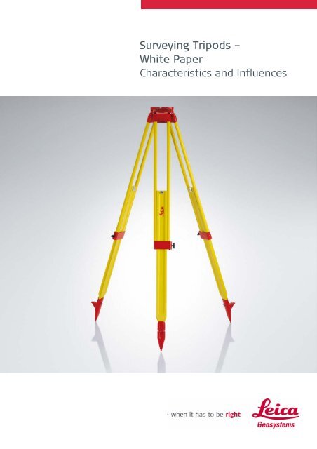
<strong>Surveying</strong> <strong>Tripods</strong> –<br />
<strong>White</strong> <strong>Paper</strong><br />
<strong>Characteristics</strong> <strong>and</strong> Influences
March 2010<br />
Daniel Nindl, Mirko Wiebking<br />
Heerbrugg, Switzerl<strong>and</strong><br />
2
<strong>Surveying</strong> tripods –<br />
characteristics <strong>and</strong> influences<br />
Daniel Nindl, Mirko Wiebking<br />
Abstract<br />
In the daily work of a surveyor, he often doesn’t<br />
think about the influence of accessories on accuracy.<br />
However, with precision surveys <strong>and</strong> measurements<br />
over long periods, the influence of accessories becomes<br />
significant. Therefore it is necessary to have<br />
some knowledge about this influence.<br />
In this paper, the effect of tripods on instrument<br />
accuracy is evaluated. The tripod requirements are<br />
defined by the International St<strong>and</strong>ard (ISO 12858-2)<br />
in terms of height stability under load <strong>and</strong> torsional<br />
rigidity. In addition to these requirements, Leica Geosystems<br />
also evaluates the horizontal drift. For this<br />
paper, these three properties were tested on a range<br />
of tripods. Using the results, recommendations are<br />
made for which tripod to use depending on the instrument<br />
<strong>and</strong> the application.<br />
Quality Criteria –<br />
St<strong>and</strong>ardized Quality Measurements<br />
according to ISO-<br />
St<strong>and</strong>ard 12858-2<br />
According to the ISO st<strong>and</strong>ard 12858-2, tripods can<br />
be classified as either heavy- or light-weight. A heavy<br />
tripod is required to have a mass of more than 5.5kg.<br />
This tripod type can support instruments up to 15kg.<br />
Lighter tripods are suitable only for instruments<br />
weighing less than 5kg. For Leica Geosystems instruments<br />
this includes only the Builder TPS, GPS antennas<br />
<strong>and</strong> prisms.<br />
Height Stability<br />
The ISO st<strong>and</strong>ard defines that the position of the<br />
tripod head may not vertically shift by more than<br />
0,05 mm when subject to double the maximum instrument<br />
weight. Therefore the heavy duty GST120-<br />
9, GST101 <strong>and</strong> Trimax require testing with 30kg. The<br />
GST05, GST05L <strong>and</strong> GST103 are defined for light duty<br />
<strong>and</strong> were tested with 10kg.<br />
The tests were all performed in stable laboratory<br />
conditions to achieve the best possible comparisons.<br />
The influence of temperature und humidity was not<br />
considered. To obtain comparable results, all tripod<br />
clamps were tightened with the same force using a<br />
torque wrench.<br />
Two tripods of each Leica Geosystems type were<br />
evaluated. In order to achieve comparable results for<br />
a fibreglass tripod, two Trimax tripods from Crane<br />
Enterprises were included in all the tests. The results<br />
of the tests were similar for Tripod A <strong>and</strong> Tripod B of<br />
each type (model). Therefore only the graphs for<br />
Tripod A are shown in this paper.<br />
Following structure is applied to the overall document:<br />
• Quality criteria – describes the relevant testparameters<br />
• Test results – summarizes <strong>and</strong> evaluates test<br />
results<br />
• User recommendations<br />
Figure 1: Quality management steps within Leica Geosystems’<br />
tribrachs assembly<br />
The defined vertical deformation of 0.05 mm is of<br />
such a small amount that the effect is insignificant on<br />
TPS angular accuracy. However, for precision leveling<br />
applications, the tripod height stability should be<br />
considered.<br />
By considering measurement accuracy <strong>and</strong> automatic<br />
capability, a Leica DNA03 Digital Level was used to<br />
measure the deformations. Measurements were<br />
made to a GWCL60 invar scale, attached to the fixing<br />
screw of the tripod (cf. figure 1). 100 measurements<br />
were first made without load on the tripod. Using a<br />
pulley system, a weight was gently lowered onto the<br />
3
tripod plate. After another 400 measurements, the<br />
weight was removed.<br />
Torsional Rigidity<br />
When an instrument rotates, the forces effect a horizontal<br />
rotation of the tripod head plate. The torsional<br />
rigidity is a characteristic of the tripod to absorb this<br />
horizontal rotation by returning to its original position<br />
when the instrument is stationary. The precision<br />
to which the tripod orientation returns to the original<br />
position is known as hysteresis.<br />
In accordance with ISO st<strong>and</strong>ard, if the tripod plate is<br />
rotated by 200 cc (ca. 70”), the maximum allowable<br />
hysteresis for heavy tripods is 10cc (3”) <strong>and</strong> for light<br />
tripods is 30cc (10”). To obtain more practical results,<br />
the effect of a rotating motorized instrument<br />
was tested. A TPS1200 was used which exerts a horizontal<br />
torque of 56Ncm while accelerating <strong>and</strong> braking.<br />
Using the application “Sets of Angles”, observations<br />
were automatically made on two prisms alternatively.<br />
This provided a rotation in both directions<br />
continuously during the observation time. Measurements<br />
were recorded for at least 200 seconds. To<br />
measure the torsional rigidity, an electronic collimator<br />
was used to monitor the deformations through the<br />
principle of autocollimation. An output frequency of<br />
16 Hz ensured rapid tracking of the deformations. A<br />
specially made plate was mounted between the tripod<br />
head <strong>and</strong> the tribrach. Measurements were made<br />
to a mirror mounted on the plate. In the picture<br />
above, a second mirror can be seen mounted on the<br />
tribrach. This allowed additional measurements to be<br />
made that took in the combined effect of the tripod<br />
<strong>and</strong> tribrach on the instrument.<br />
Horizontal Drift<br />
Figure 2 - Autocollimation mirrors mounted on tripod <strong>and</strong><br />
tribrach to detect rotational deformations<br />
The horizontal drift of a tripod is the measurement of<br />
how its orientation changes over time. This is not an<br />
ISO requirement, but Leica Geosystems checks their<br />
tripods for this drift for the sake of quality assurance.<br />
A similar measurement method as for torsional rigidity<br />
was used, but with the measurement period extended<br />
to a minimum of 3 hours. To reduce the<br />
amount data, the frequency of the collimator was<br />
reduced to 0.5Hz.<br />
The TPS1200 was again mounted in the tribrach.<br />
However, during the measurement period, the instrument<br />
remained stationary.<br />
Model Name<br />
GST120-9 GST101 Trimax GST05 GST05L GST103<br />
Material Beech wood Pine wood Fibreglass Pine wood Aluminium Aluminium<br />
Surface treatment<br />
Oil & Paint Paint Non PVC coating Non Non<br />
Leg clamp Side screw Side screw Quick-clamp Central screw Central screw Side screw<br />
Country of origin Hungary China USA Hungary Hungary China<br />
Weight 6.4 kg 5.7 kg 7.4 kg 5.6 kg 4.6 kg 4.5 kg<br />
Maximum Height 180 cm 166 cm 175 cm 176 cm 176 cm 167 cm<br />
ISO Classification Heavy Heavy Heavy Light Light Light<br />
Table 1 - Tested tripod model<br />
4
Therefore the instrument exerts no rotational force<br />
on the tripod. The movement of the tripod is only<br />
due to the instrument load. Table 1 shows a summary<br />
of different properties of the tripod models<br />
used for the particular tests.<br />
Test Results –<br />
Height Stability<br />
The GST120-9 provides the best results with a<br />
height stability of 0.02mm.<br />
Figure 3c - Crain Trimax fiberglass tripod<br />
Light <strong>Tripods</strong><br />
The GST05 shows the best performance for the light<br />
tripods. After a load of 10kg, the tripod deforms by a<br />
maximum of only 0.02mm.<br />
Figure 3a - Leica GST120-9 tripod<br />
The GST101 has 14cm shorter legs than the GST120-<br />
9, which assists in making this a more stable tripod.<br />
Figure 4a - Leica GST05 tripod<br />
The GST05L has a slightly higher vertical deformation<br />
of 0.03mm in comparison to the wooden GST05.<br />
Figure 3b - Leica GST101 tripod<br />
The Trimax has a maximum distortion of 0.05mm.<br />
This value is at the limit of the ISO requirement. The<br />
tested tripod had quick-clamps, in comparison to all<br />
Leica Geosystems tripods that use screw clamps. The<br />
clamps might be the cause for the poor height stability.<br />
Figure 4b - Leica GST05L tripod<br />
The GST103 performs similarly to the GST05L with a<br />
maximum vertical movement of 0.03mm. Although<br />
this is also a low-cost product recommended for<br />
lower accuracy instruments, the ISO criteria are still<br />
fulfilled.<br />
5
trend indicates that the hysteresis constantly increases<br />
during the set-up time.<br />
Figure 4c - Leica GST103 alu tripod<br />
Test Results –<br />
Torsional Rigidity<br />
Figure 5b - Leica GST101 wood tripod<br />
The large amplitude spikes occur during the acceleration<br />
<strong>and</strong> deceleration of the rotating instrument.<br />
Since no angular values can be recorded on the instrument<br />
during this time, these influences may be<br />
ignored. The hysteresis value is determined by examining<br />
the maximum amplitude of the graph when the<br />
spikes are disregarded.<br />
The results clearly show the difference in stability<br />
between the heavy <strong>and</strong> light tripods. The light tripods<br />
show up to several times the distortion. In addition,<br />
the fiberglass <strong>and</strong> aluminium tripods experience an<br />
overall linear trend. This means that the instrument<br />
constantly looses orientation over time.<br />
Heavy <strong>Tripods</strong><br />
Of all the tripods tested, the GST120-9 has the lowest<br />
hysteresis of 2 cc (0.7”). During the entire measurement<br />
process the tripod head plate remains extremely<br />
stable.<br />
Figure 5c – Crain Trimax fiberglass tripod<br />
Light <strong>Tripods</strong><br />
For the light tripods, the wooden GST05 proves to be<br />
the most stable with a hysteresis of 8 cc (2.7”).<br />
Both the aluminium tripods have a large rotational<br />
deviation over time. After 200 seconds, the GST05L<br />
has a hysteresis of 11 cc (3.7”) <strong>and</strong> the GST103<br />
reaches 30 cc (10”). The value of 30 cc (10”) is at the<br />
limit of the ISO st<strong>and</strong>ard for a light tripod.<br />
Figure 6a - Leica GST05 tripod<br />
Figure 5a - Leica GST120-9 tripod<br />
The GST101 results have similarly low amplitude of<br />
3 cc (1”). The Trimax shows an amplitude twice that of<br />
the other heavy tripods, of 6 cc (2”). The overall linear<br />
6
The CTP101 experiences the least drift, to a maximum<br />
of 4 cc (1.3”).<br />
Figure 6b - Leica GST05L tripod<br />
Figure 7b - Leica GST101 tripod<br />
The Trimax drifts rapidly after set-up, by as much as<br />
12 cc (4”) during the first 600 sec. However, after<br />
approximately 20 minutes the Trimax remains stable<br />
at 14 cc (4,7”).<br />
Figure 6c - Leica GST103 tripod<br />
Test Results – Horizontal Drift<br />
Similarly to the torsional rigidity test, the fiberglass<br />
<strong>and</strong> aluminium tripods loose orientation over time.<br />
This continues for approximately the first 1200 sec.<br />
After this time, the fiberglass Trimax becomes stable.<br />
The aluminium tripods continue to rotate, but at a<br />
slower rate.<br />
Heavy <strong>Tripods</strong><br />
For the GST120-9, a constant linear change occurs<br />
throughout the measurement period. However, the<br />
drift remains small at 7 cc (2.3”) after 3 hours.<br />
Figure 7c - Crain Trimax tripod<br />
Light <strong>Tripods</strong><br />
The GST05 shows to be the most stable tripod of all<br />
those tested, with a drift of less than 3 cc (1”). The<br />
aluminium tripods continue to deform for the entire<br />
measurement time. After the 3 hours, the GST05L<br />
has drifted by 23 cc (7,7”) <strong>and</strong> the GST103 by 9 cc (3”).<br />
Figure 8a - Leica GST103 tripod<br />
Figure 7a - Leica GST120-9 tripod<br />
7
Genuine Leica vs. Leica Copies<br />
Various tripod copies are available on the market.<br />
Because of their well known quality Leica Geosystems<br />
tripods are often perceived as quality-defining references.<br />
Figure 8b - Leica GST05L tripod<br />
Figure 8c - Leica GST05 tripod<br />
Table 1 - Quality management steps within Leica Geosystems’<br />
tripod assembly<br />
Hence Leica tripods are often used as a model for<br />
copying. Subsequently several manufacturers have<br />
started to make business by flooding the market with<br />
cheap tripod copies without having a warranted quality<br />
st<strong>and</strong>ard ensured. The right column in table 2<br />
shows the necessary steps to make a genuine Leica<br />
Geosystems tripod. Most of the steps are invisible to<br />
the customer, but in compliance with our strong quality<br />
management, we guarantee to supply the best<br />
products for our customers.<br />
8
Usage recommendations<br />
Table 2 summarizes the results of the all the measurements<br />
taken during this project. The values shown are<br />
the maximum error occurred during the measurement<br />
time. To determine the total effect on TPS accuracy, the<br />
hysteresis value of the tribrach is also included in the<br />
table. Leica Geosystems recommends the GDF121 (1”)<br />
with heavy tripods <strong>and</strong> the GDF111-1 (3”) with light<br />
tripods. From the total possible influence, it is clear that<br />
the tripod <strong>and</strong> tribrach have a significant effect on TPS<br />
angular accuracy. As a material, wood has been proven<br />
to provide the most stable tripod. The GST120-9 has the<br />
best results for height stability <strong>and</strong> torsional rigidity <strong>and</strong><br />
therefore suitable for all Leica TPS instruments. The<br />
horizontal drift results show that the wooden GST05 has<br />
the least distortion over an extended time. This makes<br />
the tripod ideal for GPS antennas <strong>and</strong> prism targets,<br />
which are usually set-up for long periods.<br />
Aluminium tripods provide good height stability, but<br />
poor horizontal orientation. Therefore they should be<br />
avoided for use with angular measuring instruments.<br />
Since aluminium tripods are cheaper than wooden<br />
ones, light-weight <strong>and</strong> long lasting, they are recommended<br />
for leveling applications.<br />
As shown by the horizontal drift graphs, aluminium <strong>and</strong><br />
fiberglass experiences large distortions during the first<br />
20 minutes of set-up. To obtain reliable results, it should<br />
be considered to allow this period to pass before starting<br />
observations. In addition, the orientation should be<br />
regularly checked during the measurement process.<br />
The tripod analysis tests were all made under laboratory<br />
conditions. However, under normal field conditions, further<br />
effects such as temperature, humidity, ground type,<br />
wind, etc. additionally affect stability. As tripods age, it<br />
can also be expected that their stability would decrease.<br />
Therefore the influence of the tripod <strong>and</strong> tribrach must<br />
always be considered when determining the angular<br />
accuracy that can be achieved.<br />
Using the values in the table the most suitable tripod can<br />
be chosen for the required surveying application. For<br />
precision surveys over long periods, it is recommended<br />
to use a concrete pillar. Alternatively, a sophisticated<br />
measurement process should be used which compen<br />
sates for these errors.<br />
Model Name GST120-9 GST101 Trimax GST05 GST05L GST103<br />
Leica product for which<br />
GPS antenna<br />
All TPS All TPS TPS >5”<br />
suitable<br />
Prisms<br />
Prisms Levels Prisms Levels<br />
Material Beech wood Pine wood Fibreglass Pine wood Aluminium Aluminium<br />
ISO Classification Heavy Heavy Heavy Light Light Light<br />
Height stability 0.02 mm 0.03 mm 0.05 mm 0.02 mm 0.03 mm 0.03 mm<br />
Tripod hysteresis 1” (2 cc ) 1” (3 cc ) 2” (6 cc ) 3” (8 cc ) 4” (11 cc ) 10” (30 cc )<br />
Tribrach hysteresis 1” (3 cc ) 1” (3 cc ) 1” (3 cc ) 3” (10 cc ) 3” (10 cc ) 3” (10 cc )<br />
Max. possible influence 2” (5 cc ) 2” (6 cc ) 3” (9 cc ) 6” (18 cc ) 7” (21 cc ) 13” (40 cc )<br />
Hz Drift after 3 hours 2” (7 cc ) 1” (4 cc ) 5” (14 cc ) 1” (3 cc ) 8” (23 cc ) 3” (9 cc )<br />
Table 2 - Summary of results <strong>and</strong> recommendations<br />
Source<br />
This document is a summary <strong>and</strong> translation of the<br />
Thesis named Genauigkeitsanalyse von<br />
Vermessungsstativen und Dreifüssen unter der Belastung<br />
verschiedener Instrumente. The Thesis was conducted<br />
during 2006 by Daniel Nindl of the Department Geodesy<br />
Engineering, Technical University of Vienna, under guidance<br />
of Mirko Wiebking of Leica Geosystems AG, Heerbrugg.<br />
The purpose of the thesis study was to analyses<br />
the effect of tripods <strong>and</strong> tribrachs on instrument accuracy.<br />
The analysis of tribrachs is not included within this<br />
document, but there is an additional white paper available,<br />
called: “<strong>Surveying</strong> Tribrachs – <strong>Characteristics</strong> <strong>and</strong><br />
Influences”.<br />
9
Whether you want to monitor a bridge or a volcano, survey a skyscraper<br />
or a tunnel, stake out a construction site or perform control<br />
measurements – you need reliable equipment. With Leica Geosystems<br />
original accessories, you can tackle dem<strong>and</strong>ing tasks. Our accessories<br />
ensure that the specifications of the Leica Geosystems instruments<br />
are met. Therefore you can rely on their accuracy, quality <strong>and</strong> long life.<br />
They ensure precise <strong>and</strong> reliable measurements <strong>and</strong> that you get the<br />
most from your Leica Geosystems instrument.<br />
When it has to be right.<br />
Illustrations, descriptions <strong>and</strong> technical specifications are not binding <strong>and</strong> may change.<br />
Printed in Switzerl<strong>and</strong>–Copyright Leica Geosystems AG, Heerbrugg, Switzerl<strong>and</strong>, 2019.<br />
VII.10 –INT<br />
Leica Geosystems AG<br />
Heerbrugg, Switzerl<strong>and</strong><br />
www.leica-geosystems.com