Installation Instructions - Right Stuff Detailing
Installation Instructions - Right Stuff Detailing
Installation Instructions - Right Stuff Detailing

Create successful ePaper yourself
Turn your PDF publications into a flip-book with our unique Google optimized e-Paper software.
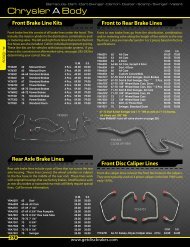
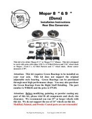
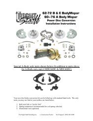
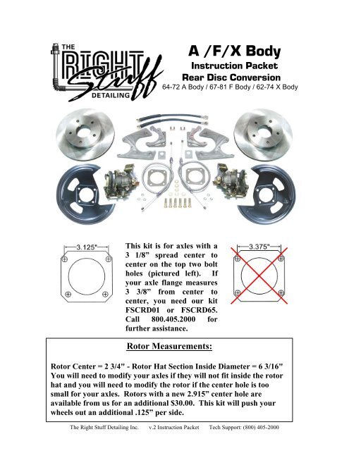
A /F/X Body<br />
Instruction Packet<br />
Rear Disc Conversion<br />
64-72 A Body / 67-81 F Body / 62-74 X Body<br />
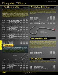
This kit is for axles with a<br />
3 1/8” spread center to<br />
center on the top two bolt<br />
holes (pictured left). If<br />
your axle flange measures<br />
3 3/8” from center to<br />
center, you need our kit<br />
FSCRD01 or FSCRD65.<br />
Call 800.405.2000 for<br />
further assistance.<br />
Rotor Measurements:<br />
Rotor Center = 2 3/4" - Rotor Hat Section Inside Diameter = 6 3/16"<br />
You will need to modify your axles if they will not fit inside the rotor<br />
hat and you will need to modify the rotor if the center hole is too<br />
small for your axles. Rotors with a new 2.915” center hole are<br />
available from us for an additional $30.00. This kit will push your<br />
wheels out an additional .125” per side.<br />
The <strong>Right</strong> <strong>Stuff</strong> <strong>Detailing</strong> Inc. v.2 Instruction Packet Tech Support: (800) 405-2000
Note: If you are interested in Power Coated Calipers or<br />
Drilled and Slotted Rotors we have these upgrades available<br />
for exchange of non-installed components and an upgrade fee.<br />
If you are interested in Emergency Brake Cables for the front<br />
of your car please give us a call. We cannot exchange<br />
components that have been previously installed. Shipping<br />
charges will apply. Upgrades pictured.<br />
Attention: Before modifying, painting, or powder coating any<br />
part of this kit, please trial fit all components and check rim<br />
clearance. We recommend you run 15” or larger wheels with<br />
this kit. We do not support the use of 14” wheels on this kit.<br />
Modified, Painted, and Powder Coated parts are not returnable!<br />
*Note: The emergency brake cables provided in the kit will fit 64 –72 A<br />
Body / 67-81 F Body / 62-74 X Body. Any other application will require the<br />
customer to purchase or modify the included cables to work with their application.<br />
If you ordered a non-ebrake kit your kit will not contain emergency brake cables.<br />
The <strong>Right</strong> <strong>Stuff</strong> <strong>Detailing</strong> Inc. v.2 Instruction Packet Tech Support: (800) 405-2000
Kit Contents:<br />
____ Pair of Rotors (BR25C for plain rotors, BR25ZDC rotors for drilled<br />
and slotted rotors)<br />
____Pair of calipers (BC3839N for a non-staggered kit, BC3939N calipers<br />
for a staggered kit, if powder coated calipers were selected there will be<br />
a letter pertaining to the color of the caliper within the part number as<br />
well)<br />
____Set of caliper brackets (CMB81 for a non-staggered kit and CMB85<br />
for a staggered)<br />
____Pair of Flex Hoses (FHK09 for regular, FHK09S for braided stainless)<br />
____Pair of Dust Shields (DBBP81 for a non-staggered kit, DBBP81 L x 2<br />
for a staggered kit)<br />
____Pair of Emergency brake cables (EBCRD1/EBCRD1 for 64-72 GM<br />
A-Body/67 F-Body Part # AFXRD01, EBCRD1/EBCRD2 for 68-69<br />
GM F-Body Part # AFXRD05, EBCRD1/EBCRD2 for 68-74 GM<br />
X-Body Part # AFXRD05, EBCRD4 for 62-67 Nova Part #<br />
AFXRD01N, EBCRD5/EBCRD6 for 70-74 GM F-Body Part #<br />
AFXRD06, EBCRD7/EBCRD8 for 75-81 GM F-Body Part #<br />
AFXRD07)<br />
____Instruction Packet<br />
* See the back page of the instruction booklet to review the “Pick Ticket”<br />
used to pull your order.<br />
The <strong>Right</strong> <strong>Stuff</strong> <strong>Detailing</strong> Inc. v.2 Instruction Packet Tech Support: (800) 405-2000
Disclaimer:<br />
The <strong>Right</strong> <strong>Stuff</strong> values your safety above all things. For this reason, we<br />
recommend all brake systems and components be installed by professionals.<br />
The installer of the brake parts is responsible for ensuring fitment and<br />
suitability of the parts for the vehicle it is being installed on. Brakes should<br />
be tested in a controlled open area with success before driving on the road.<br />
If you are unsure or uncomfortable with any part of your kit, please call for<br />
further instructions from our tech staff before driving.<br />
The <strong>Right</strong> <strong>Stuff</strong> <strong>Detailing</strong> Inc. v.2 Instruction Packet Tech Support: (800) 405-2000
<strong>Installation</strong> <strong>Instructions</strong>:<br />
Before installing this kit on your car please watch the<br />
instructional video at www.getdiscbrakes.com under tech stuff.<br />
1. Prepare the car<br />
Begin by securely supporting the car on jack stands. Chock the front wheels to be sure<br />
vehicle does not roll. Always work on a flat, even surface. Remove the wheels to gain<br />
access to the factory drum brakes.<br />
2. Remove the old drum brakes<br />
”C” Clip Axles<br />
“C” Clip rear ends require you to open the rear housing cover and remove the “C” clips<br />
before removing the axles. After removing the clips, your axles should pull out of the<br />
axle tubes.<br />
Note: Most “C” clip eliminator kits can be used with our conversion. Due to the wide<br />
variety of eliminator kit manufacturers, we can’t guarantee their compatibility with our<br />
kit. Changes in track width can occur.<br />
After the axles are out, you can unbolt the drum brakes and remove them as a complete<br />
assembly. There is no need to remove the drum shoes and hardware before removing the<br />
backing plate. Dress the front and back of the axle flange with some steel wool or a wire<br />
brush to prepare it for the new caliper brackets.<br />
Drop Out Axles<br />
Unbolt the axle flange from the rear housing to free the axle. After unbolting the flange,<br />
your axles should pull out of the axle tubes.<br />
After the axles are out, you can unbolt the drum brakes and remove them as a complete<br />
assembly. There is no need to remove the drum shoes and hardware before removing the<br />
backing plate. Dress the front and back of the axle flange with some steel wool or a wire<br />
brush to prepare it for the new caliper brackets.<br />
The <strong>Right</strong> <strong>Stuff</strong> <strong>Detailing</strong> Inc. v.2 Instruction Packet Tech Support: (800) 405-2000
3. Install Dust Shields (Optional)<br />
****Please Disregard the “L” and “R” markings on the backing plates.<br />
Just be sure that the opening for the caliper faces the rear on both sides<br />
for non-staggered shocks. For staggered shocks, the caliper opening<br />
should face the rear on the passenger side and toward the front on<br />
driver side****<br />
Before you re-install your rear axles you need to install the included dust shields if you<br />
have decided that you want to use them. Place the dust shield on the front of the axle<br />
flange with the opening for the caliper at the 2 o’clock position on the driver’s side and<br />
the 10 o’clock position on the passenger’s side.* After this is completed you can<br />
reinstall your axles. You will actually bolt the shields in place when you bolt the caliper<br />
bracket onto the rear end in step 5.<br />
*Attention Staggered Shock Owners:<br />
Staggered shock rear ends require you to mount the driver’s side dust shield towards the<br />
front of the car. The passenger’s side dust shield still mounts towards the rear of the car.<br />
Make sure you have the correct kit for staggered shocks (AFXRD05, AFXRD06,<br />
AFXRD07)<br />
4. Re-install the axles<br />
”C” Clip Axles<br />
Push the axles back in the tube and install the “C” clips. Replace the housing gasket and<br />
re-install the cover. The flange spacer pictured to the bottom right is not required on “C”<br />
clip installations. Do not bolt the axle flange in place at this time.<br />
Drop Out Axles<br />
Drop out axles require a flange spacer (pictured right) to take the<br />
place of the old drum backing plate. Place the spacer on the flange<br />
and slide the axle back in the tube. Do not bolt the axle flange in<br />
place at this time. Do not use this spacer if you are using the<br />
optional dust shields as they are welded into the backing plates.<br />
The <strong>Right</strong> <strong>Stuff</strong> <strong>Detailing</strong> Inc. v.2 Instruction Packet Tech Support: (800) 405-2000
5. Install the new caliper brackets<br />
The new caliper brackets mount to the back (inboard) side of the axle flange. The<br />
recessed machined surface should face the axle flange. The Caliper opening should face<br />
the rear of the car.* Place the large 1/4” spacer between the bracket and flange as shown<br />
below. The other spacers are not required at this time. Bolt the assembly together with<br />
the supplied hardware. If you have a problem with the pads hitting the rotors, see step 6<br />
for information on adjusting the caliper spacing.<br />
*Attention Staggered Shock Owners:<br />
Staggered shock rear ends require you to mount the driver’s side caliper towards the front<br />
of the car. The passenger’s side caliper still mounts towards the rear of the car. Make<br />
sure you have the correct kit for staggered shocks (AFXRD05, AFXRD06, AFXRD07)<br />
Machined Surface<br />
The <strong>Right</strong> <strong>Stuff</strong> <strong>Detailing</strong> Inc. v.2 Instruction Packet Tech Support: (800) 405-2000
6. Install the rotors<br />
Before installing the rotor, dress the center hub with steel wool or a wire brush. Slide the<br />
rotor over the studs and tighten it down with two or three lug nuts. Occasionally, the<br />
center opening in the rotor is too small to slide over the hub. You’ll need to enlarge it<br />
slightly with a die grinder, file or have it machined by a machine shop. If the center hole<br />
of your rotor is too small for your axle hub we can have a set of rotors machined for you<br />
for an additional $30.00 fee, shipping charges will apply. Rotors with a new 2.915”<br />
center hole are available from us for an additional $30.00 (with exchange of nonmachined<br />
rotors) as well, shipping charges will apply.<br />
7. Install and center the calipers<br />
Position the caliper in the bracket and install the caliper mounting pins. Be sure the<br />
mounting ears are on the backside of the caliper brackets. The parking brake assembly<br />
should be on top with the bleeder pointing towards the front of the<br />
car.* If the pads do not clear the rotor, you’ll need to adjust the<br />
caliper position with the included spacers.<br />
If the inside pad hits the rotor, you’ll need to add spacers between the<br />
flange and caliper bracket. If the outside pad hits the rotor, you’ll<br />
need to use one of the smaller spacers or remove the spacers<br />
completely. Spacers can be stacked to achieve the required thickness.<br />
*Attention Staggered Shock Owners:<br />
Staggered shock rear ends will have the emergency brake assembly pointing two different<br />
directions. The driver’s side assembly will point towards the rear of the car and the<br />
passenger’s side assembly will point towards the front of the car. Make sure you have<br />
the correct kit for staggered shocks (AFXRD05, AFXRD06, AFXRD07)<br />
The <strong>Right</strong> <strong>Stuff</strong> <strong>Detailing</strong> Inc. v.2 Instruction Packet Tech Support: (800) 405-2000
8. Attach the flex hoses<br />
Remove the banjo bolt and copper washers from the caliper. Place a copper washer on<br />
top of the flex hose and insert the banjo bolt. Place the second copper washer over the<br />
banjo bolt on the bottom of the flex hose and bolt the hose onto the caliper with the<br />
specifications provided in the assembly manual.<br />
9. Install the emergency brake cables and<br />
adjust the calipers<br />
You rear disc conversion comes with new rear emergency<br />
brake cables. You’ll use the existing intermediate and<br />
front cables on your car. Run the cable up thru the<br />
center of the spring and insert the metal bung on the<br />
end of the cable securely into the notch on the emergency<br />
brake lever. No clip is required to hold the cable to the caliper.<br />
Attach the other end to your existing intermediate cable using the<br />
included hardware.<br />
After the cables are installed, you need to adjust the system. Engage and release the<br />
emergency brake lever several times to activate the self-adjustment mechanism built into<br />
the calipers. You’ll know you’ve got it when emergency brake is fully engaged and the<br />
rear wheels will no longer turn by hand. If your rear caliper pistons do not ratchet out by<br />
use of the e-brake arm on the caliper follow the following procedure to get the piston to<br />
extend the brake pads to the rotor surface. Remove the spring and the e-brake arm from<br />
the caliper. Turn the threaded bolt extending from the body of the caliper by hand or<br />
with the aid of a wrench. Continue to turn the bolt until the brake pads come in contact<br />
with the rotor. After the pad comes into contact with the rotor back the bolt out until the<br />
first position that you can put the arm back on. After the desired adjustment is achieved<br />
reattach the e-brake arm and the spring onto the caliper. Continue with the bleeding<br />
procedure.<br />
Note: It is important that you regularly use the emergency brake to keep them properly<br />
adjusted.<br />
*Attention Staggered Shock Owners:<br />
Staggered shock rear ends require two different length brake cables. The short cable is<br />
used on the passenger’s side. The longer cable comes out of the driver’s side caliper<br />
towards the back of the car and loops back around to the front. Make sure you have the<br />
correct kit for staggered shocks (EBCRD1/EBCRD2 for 68-69 GM F-Body & 68-74 GM<br />
X-Body Part # AFXRD05, EBCRD5/EBCRD6 for 70-74 GM F-Body Part # AFXRD06,<br />
EBCRD7/EBCRD8 for 75-81 GM F-Body Part # AFXRD07)<br />
The <strong>Right</strong> <strong>Stuff</strong> <strong>Detailing</strong> Inc. v.2 Instruction Packet Tech Support: (800) 405-2000
10. Install the flex house mounting tabs<br />
Before installing these tabs you either need to shorten your existing rear axle lines or<br />
purchase a pre-shortened rear axle line set. The shortening of the rear axle line is<br />
necessary to compensate for the flex hose coming off of the caliper. As a general rule of<br />
thumb your lines will be about 6” – 8” shorter than the factory lines. Mount these tabs<br />
where your hard lines end. They will need to be tack welded to your rear axle housing.<br />
It is ok to tack weld the tabs after your rear end has been assembled. After they have<br />
been welded to your axle housing, insert your flex hose into the bracket and secure with<br />
the flex hose clip provided. After you have secured your hose into the bracket, screw<br />
your axle line into the end of the flex hose and tighten it with a wrench.<br />
The <strong>Right</strong> <strong>Stuff</strong> <strong>Detailing</strong> Inc. v.2 Instruction Packet Tech Support: (800) 405-2000
11. Bleed the system<br />
Before bleeding your brakes please watch the instructional<br />
video at www.getdiscbrakes.com under tech stuff.<br />
If you are concerned with the damaging effects of DOT 3 brake fluid, The <strong>Right</strong> <strong>Stuff</strong><br />
suggests synthetic DOT 5. The <strong>Right</strong> <strong>Stuff</strong> is not liable for damage caused by system<br />
fluids.<br />
Make sure the emergency brakes have been adjusted properly as discussed in step<br />
eight before bleeding the brakes. Working your way forward from the wheel farthest<br />
from the master cylinder will help insure a good bleed and a firm pedal. It is important to<br />
bleed the system in the following order:<br />
1. <strong>Right</strong> Rear 2. Left Rear 3. <strong>Right</strong> Front 4. Left Front<br />
Attention:<br />
The bleeder screws must be positioned horizontally. If the bleeders are pointed down, the<br />
calipers will trap air and the system will not bleed properly. You can remove the caliper<br />
mounting pins and rotate the caliper to re-position the bleeder. Remember to keep the<br />
pads over the rotor when rotating the caliper. The picture below shows how you need to<br />
re-position the bleeder to get all the air out of the system.<br />
The <strong>Right</strong> <strong>Stuff</strong> <strong>Detailing</strong> Inc. v.2 Instruction Packet Tech Support: (800) 405-2000
Technical Support<br />
We want your conversion project to go smoothly. Double check that you have followed<br />
these instructions correctly and those included with any upgrade components you may<br />
have purchased. If you need additional help getting your new disc brakes to function<br />
properly, we’re here for you. You can visit our website at www.GetDiscBrakes.com for<br />
Tech Tips, Tricks & Videos. If you are having trouble getting a good pedal please take a<br />
moment to watch the rear disc installation support video. If you cannot find the<br />
assistance you need from that source feel free to send us an email from the Tech support<br />
section of the website for priority service. If you are still unable to get the help you need,<br />
please feel free to give us a call at (800) 405-2000.<br />
Thank You for Your Business!<br />
No part of this document may be reproduced without written permission of The <strong>Right</strong> <strong>Stuff</strong> <strong>Detailing</strong> Inc. The information contained in this document<br />
is based on information we believe to be true and reliable, however the accuracy or completeness thereof is not guaranteed.<br />
The <strong>Right</strong> <strong>Stuff</strong> <strong>Detailing</strong> Inc. v.2 Instruction Packet Tech Support: (800) 405-2000
The <strong>Right</strong> <strong>Stuff</strong> <strong>Detailing</strong> Inc. v.2 Instruction Packet Tech Support: (800) 405-2000
Pick Ticket:<br />
The <strong>Right</strong> <strong>Stuff</strong> <strong>Detailing</strong> Inc. v.2 Instruction Packet Tech Support: (800) 405-2000