Test Receiver R&S®ESPI - Rohde & Schwarz
Test Receiver R&S®ESPI - Rohde & Schwarz
Test Receiver R&S®ESPI - Rohde & Schwarz
You also want an ePaper? Increase the reach of your titles
YUMPU automatically turns print PDFs into web optimized ePapers that Google loves.
Data sheet<br />
Version<br />
05.03<br />
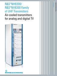
<strong>Test</strong> <strong>Receiver</strong> R&S ® ESPI<br />
May<br />
2009<br />
The precompliance standard up to 7 GHz<br />
Excellent test receiver features<br />
◆ Choice of 7 detectors<br />
◆ EMI measurement bandwidths<br />
200 Hz, 9 kHz, 120 kHz, 1 MHz<br />
◆ Pulse weighting with quasi-peak,<br />
average and RMS average detector<br />
in accordance with the latest<br />
CISPR 16-1-1 edition<br />
◆ For all commercial EMI standards<br />
Extremely high measurement speed<br />
◆ Measurement times<br />
from 100 µs to 100 s<br />
◆ Option: preselector and<br />
20 dB preamplifier<br />
Spectrum analyzer<br />
◆ IF resolution bandwidths<br />
from 10 Hz to 10 MHz<br />
◆ <strong>Test</strong> routines for TOI, ACP, OBW,<br />
CCDF<br />
Outstanding performance features<br />
◆ Total measurement uncertainty<br />
– Spectrum analyzer mode: 0.5 dB<br />
(without preselection)<br />
– <strong>Receiver</strong> mode:
Precompliance <strong>Test</strong> <strong>Receiver</strong>/Spectrum Analyzer R&S ® ESPI...<br />
◆ Optimized operating concept owing to<br />
decades of experience in EMI test<br />
receiver development<br />
◆ Very high measurement speed<br />
◆ High measurement accuracy<br />
With the two ¸ESPI test receiver<br />
models, the well-known advantages of<br />
the ¸ESIB high-end compliance test<br />
receivers/analyzers have been systematically<br />
implemented for the upper middleend.<br />
Due to a common platform system, the<br />
user has the additional benefits of the<br />
¸FSP spectrum analyzer family which<br />
is already in place. These benefits by far<br />
exceed the capabilities and functions of<br />
conventional precompliance test equipment.<br />
The ¸ESPI defines the vital criteria,<br />
such as functionality, measurement speed<br />
and accuracy for middle-end equipment.<br />
The use of innovative techniques, such as<br />
the VLSI frontend and largely digital<br />
signal processing, together with ASICs<br />
developed by <strong>Rohde</strong> & <strong>Schwarz</strong>, has<br />
resulted in a product with top-class<br />
specifications and high reliability.<br />
Outstanding features<br />
TEST RECEIVER<br />
◆ Peak, Quasi-Peak, Average, CISPR<br />
Average, RMS and RMS Average<br />
(max. 3 detectors simultaneously)<br />
◆ EMI measurement bandwidths<br />
200 Hz, 9 kHz, 120 kHz, 1 MHz<br />
◆ Correct pulse weighting in line with<br />
CISPR 16-1-1 from 10 Hz pulse repetition<br />
frequency<br />
◆ For all commercial EMI standards<br />
such as CISPR, EN, ETS, FCC, ANSI<br />
C63.4, VCCI and VDE<br />
◆ Option ¸ESPI-B2:<br />
Preselector and 20 dB preamplifier<br />
SPECTRUM ANALYZER<br />
◆ Resolution bandwidths from 10 Hz<br />
to 10 MHz (in 1/3/10 sequence)<br />
◆ RMS detector for measurements on<br />
digitally modulated signals<br />
◆ <strong>Test</strong> routines for TOI, ACPR, OBW,<br />
amplitude statistics<br />
Unprecedented<br />
measurement speed<br />
◆ Fast detection of critical frequencies<br />
through overview measurements:<br />
– Measurement time 100 µs to 100 s<br />
in receiver mode<br />
– up to 16 000 s in analyzer mode<br />
2 <strong>Test</strong> <strong>Receiver</strong> ¸ESPI
...the standard in the EMI precompliance class<br />
EMC-relevant<br />
performance features<br />
◆ Total measurement uncertainty<br />
– Spectrum analyzer mode: 0.5 dB<br />
(without preselection)<br />
– <strong>Receiver</strong> mode:
Accuracy and reproducibility are also key<br />
parameters for all applications of the<br />
¸ESPI test receiver family.<br />
The combination of test receiver and<br />
spectrum analyzer provides an optimum<br />
concept for precompliance measurements<br />
in development environments.<br />
Standard-conforming EMI<br />
measurements<br />
Fitted with the optional preselector/preamplifier<br />
(¸ESPI-B2), all ¸ESPI<br />
models feature an excellent dynamic<br />
range compared with other precompliance<br />
solutions and are, therefore, able to<br />
perform precise interference measurements<br />
with pulse repetition frequencies<br />
(PRF) from 10 Hz in line with<br />
CISPR 16-1-1.<br />
¸ESPI-B2: preamplifier and preselection filters up to 3 GHz<br />
The input stages of precompliance test equipment, which often feature<br />
a rather poor overload capability, would be hopelessly overdriven<br />
without a preselection unit. This is different with the ¸ESPI where,<br />
in combination with preselection filter units, a low-noise preamplifier<br />
comes after the filter module but before the mixer stage. It must be<br />
possible to switch the preamplifier on/off as required, since in the case<br />
of high signal levels, the dynamic range would be reduced by an amount<br />
numerically equal to the gain. Where low signal levels are to be<br />
expected, it is best to switch in the preamplifier. Since the <strong>Test</strong><br />
<strong>Receiver</strong>s ¸ESPI operate both in the spectrum analyzer mode and in<br />
the test receiver mode, both modes offer the choice of switching the<br />
preamplifier on or off. In the receiver mode, the preselection filter<br />
setting is fixed, whereas in the analyzer mode it can be selected.<br />
Measurements to commercial EMI standards<br />
such as CISPR, EN 550xx, ETS, FCC,<br />
ANSI C63.4, VCCI or VDE can be carried<br />
out directly by comparing the EMI spectrum<br />
with the associated limit lines and<br />
switching on the appropriate detectors<br />
(PK, QP, CAV, AV, RMS-AV, RMS).<br />
The detectors<br />
Spectrum analyzer mode with selectable preselection filters and preamplifier switched on<br />
Depending on the operating mode of the<br />
¸ESPI 3 and ¸ESPI 7, i.e. spectrum<br />
analyzer or test receiver, the following<br />
detectors are available:<br />
◆ Analyzer mode: MaxPeak, MinPeak,<br />
AutoPeak, Sample, Quasi-Peak,<br />
Average, CISPR Average, RMS,<br />
RMS Average<br />
◆ <strong>Receiver</strong> mode: MaxPeak, MinPeak,<br />
Quasi-Peak, Average, CISPR Average,<br />
RMS, RMS Average<br />
Up to 3 detectors can be activated simultaneously<br />
and the results displayed.<br />
The bargraph display, with current detector<br />
value and MaxHold display, clearly<br />
shows the results of manual circuit<br />
adjustment when the DUT cabling is<br />
arranged for maximum emissions and<br />
when the antenna is aligned relative to<br />
the DUT for a maximum reading.<br />
In the receiver mode, the QP detector is<br />
coupled with the time constants, prescribed<br />
by the standard, as a function of<br />
the frequency range. This ensures that<br />
the correct time constants and IF bandwidth<br />
are used for signal weighting in the<br />
CISPR bands. This means much greater<br />
ease of operation for the user.<br />
4 <strong>Test</strong> <strong>Receiver</strong> ¸ESPI
The measurement bandwidths<br />
The measurement bandwidths of the<br />
¸ESPI are designed for a large variety<br />
of applications:<br />
The analyzer mode provides all –3 dB<br />
bandwidths from 10 Hz to 10 MHz<br />
(in 1/3/10 sequence). In the receiver<br />
mode, the –6 dB bandwidths can also be<br />
selected by softkey: 200 Hz, 9 kHz,<br />
120 kHz plus 1 MHz bandwidth.<br />
Moreover, approx. 40 digital channel<br />
filters are available.<br />
Like the detectors, the standard-conforming<br />
CISPR bandwidths can be coupled as<br />
a function of the frequency range. If<br />
necessary, the coupling can be disabled.<br />
The preselector/preamplifier option<br />
(¸ESPI-B2) is available as a protection<br />
against overloading by pulsed, highpower<br />
signals and for ensuring the validity<br />
of signal evaluation in the linear operating<br />
range of the measuring instrument.<br />
The advantage of this option is that, in<br />
the analyzer mode, the preselection filters<br />
or the preamplifier can be switched<br />
on or off as required.<br />
User-selectable parameters in<br />
up to 10 subranges<br />
SCAN table<br />
The basis for all reproducible measurements<br />
is a scan table with up to ten subranges<br />
and user-programmable frequency<br />
parameters such as START, STOP,<br />
STEP SIZE, resolution bandwidth, measurement<br />
time per frequency as well as<br />
RF attenuation setting at a constant value<br />
or coupled to AUTO RANGE overload<br />
monitoring. For sensitive measurements<br />
(if low signal levels are expected), the<br />
preamplifier can be switched on or off as<br />
a function of the subrange.<br />
<strong>Test</strong> <strong>Receiver</strong> ¸ESPI 5
Diagram and graphics display can most<br />
easily be defined via ADJUST AXIS.<br />
Marker functions and<br />
split-screen display<br />
In addition to normal FULL SCREEN<br />
display, a second window is opened in<br />
the SPLIT SCREEN mode for bargraph<br />
display with current detector values and<br />
MaxHold display. By activating "Tune to<br />
Marker" the receive frequency and the<br />
amplitude of the detectors coupled to the<br />
marker are displayed as a bargraph and<br />
numerically. This makes things considerably<br />
easier for the user.<br />
The split-screen display in the analyzer<br />
mode makes it possible to resolve fine<br />
spectrum detail. By coupling the marker<br />
frequency (in screen B) to the center frequency<br />
of screen A, parameters such as<br />
bandwidth, span, RF attenuation can be<br />
selected separately to detect spurious<br />
which are close to the signal and cannot<br />
be seen in the overview spectrum.<br />
6 <strong>Test</strong> <strong>Receiver</strong> ¸ESPI
R&S ® ESPI – the optimal balance<br />
of price and performance<br />
◆ Large 21 cm display with brilliant<br />
colors which makes it easy to read parameters<br />
and displays results clearly<br />
◆ Seven different detectors including<br />
average detector with meter time<br />
constant (CISPR Average) and RMS<br />
average detector, up to three of them<br />
can be selected simultaneously<br />
◆ EMI bandwidths 200 Hz, 9 kHz,<br />
120 kHz and 1 MHz<br />
◆ Resolution bandwidths from 10 Hz<br />
to 10 MHz<br />
◆ Editable limit lines<br />
◆ Correction tables for transducers,<br />
coupling networks, accessories,<br />
antennas<br />
◆ Convenient documentation of results<br />
as a hardcopy or file in PC-compatible<br />
formats<br />
◆ Interfaces: GPIB, Centronics,<br />
RS-232-C, LAN (option)<br />
◆ Automatic test routines for measurement<br />
of TOI, OBW, phase noise,<br />
ACP(R)<br />
Overview of limit lines<br />
◆ Split-screen display with independent<br />
settings and up to 3 traces per screen<br />
◆ Fast measurements in the time<br />
domain: minimum sweep time 1 µs<br />
◆ Gated sweep for measurements on<br />
TDMA signals<br />
◆ Minimum sweep time of 2.5 ms,<br />
supports daily efforts in the lab to cut<br />
development times<br />
Additional applications –<br />
extra performance<br />
Modern communications systems are<br />
required to achieve optimum spectral<br />
efficiency at high data rates. For the 3rd<br />
generation CDMA mobile radio systems<br />
currently under development, this is<br />
achieved by a number of measures, for<br />
example high-precision power control.<br />
The ¸ESPI is the ideal measurement<br />
tool for diagnostic measurements,<br />
development, precertification and postcertification<br />
owing to its excellent RF<br />
characteristics:<br />
◆ Total measurement uncertainty<br />
– Spectrum analyzer mode: 0.5 dB<br />
(without preselection)<br />
– <strong>Receiver</strong> mode:
The R&S ® ESPI comes as standard with a large variety of<br />
functions<br />
Fit for the future<br />
Owing to its modular design, the<br />
¸ESPI is optimally equipped to<br />
handle today’s measurements and the<br />
measurements of the future. The design<br />
already takes into account both hardware<br />
and firmware extensions so that the<br />
¸ESPI will meet all requirements in<br />
the years to come as well. A safe investment<br />
for the future.<br />
Ergonomics&design<br />
The ¸ESPI sets the new standard in<br />
the precompliance class. The 21 cm (8.4")<br />
color display makes it easy for the user to<br />
read results and provides an overview of<br />
the parameters which have been<br />
selected.<br />
Vertical and horizontal rows of softkeys<br />
make it easy to perform even complex<br />
measurements. Parameters such as frequency<br />
and amplitude are entered by<br />
means of dedicated hardkeys and unit<br />
keys.<br />
Wide dynamic range<br />
Featuring the lowest displayed average<br />
noise level in its class (DANL typ.<br />
–145 dBm at 10 Hz RBW), the ¸ESPI<br />
measures even small signals precisely,<br />
when using the optional Preselector/Preamplifier<br />
¸ESPI-B2 from 9 kHz to<br />
3 GHz even down to –153 dBm (10 Hz<br />
RBW). Together with the high intercept<br />
point, this yields an intermodulation-free<br />
range of typ. 100 dB – an excellent value<br />
even for higher middle-end instruments.<br />
Phase noise<br />
Displayed<br />
average noise<br />
level in receiver<br />
mode with<br />
preselector/<br />
preamplifier<br />
switched on<br />
The ¸ESPI’s minimal phase noise<br />
makes it suitable for demanding measurements<br />
both close to the carrier<br />
(typ. –113 dBc (1 Hz) at 10 kHz) and far<br />
from the carrier (typ. –125 dBc (1 Hz) at<br />
1 MHz). The ¸ESPI is therefore optimally<br />
equipped for performing spectral<br />
analysis and ACPR measurements on narrowband<br />
systems such as IS-136 or PDC<br />
as well as on wideband systems such as<br />
IS-95 or WCDMA.<br />
Interior view: modular design of test receiver<br />
8 <strong>Test</strong> <strong>Receiver</strong> ¸ESPI
Spectrum analyzer application,<br />
ACPR measurements<br />
Measurement of the adjacent-channel<br />
power ratio (ACPR), which many mobile<br />
radio standards stipulate for components<br />
and units, is performed in the ¸ESPI<br />
analyzer mode by automatic test routines.<br />
All settings, measurements and filters<br />
required for a selected standard are<br />
activated at a keystroke.<br />
In addition to a large number of preprogrammed<br />
standards, the channel width<br />
and channel spacing can be selected as<br />
required.<br />
TOI measurement<br />
Due to its excellent dynamic range, the<br />
lowest phase noise in its class and its<br />
RMS detector, the ¸ESPI sets the<br />
new standard for the upper middle-end –<br />
even for ACPR measurements.<br />
<strong>Test</strong> routines for TOI, OBW, etc<br />
are standard<br />
The ¸ESPI offers fast test routines for<br />
a multitude of typical laboratory measurements.<br />
The routines make postprocessing<br />
superfluous and supply results<br />
directly:<br />
◆ Determination of TOI<br />
◆ Occupied bandwidth (OBW)<br />
◆ Burst power with peak, average and<br />
RMS indication as well as standard<br />
deviation<br />
◆ Modulation depth of AM signals<br />
◆ Phase noise<br />
◆ Bandwidth marker<br />
Of course, these functions can also be<br />
used via the fast GPIB interface.<br />
<strong>Test</strong> <strong>Receiver</strong> ¸ESPI 9
Optional tracking generator<br />
9 kHz to 3 GHz<br />
The optional Internal Tracking Generator<br />
¸FSP-B9 up to 3 GHz and External<br />
Generator Control ¸FSP-B10<br />
enhance the two ¸ESPI test receiver<br />
models to yield scalar network analyzer<br />
functionality. Gain, frequency response,<br />
insertion and return loss are measured<br />
using a selective method with a wide<br />
dynamic range without being affected by<br />
harmonics or spurious from the generator.<br />
The Internal Tracking Generator<br />
¸FSP-B9 can be used in both<br />
¸ESPI models and covers the frequency<br />
range from 9 kHz to 3 GHz. A frequency<br />
offset of ±150 MHz can be set for<br />
measurements on frequency-converting<br />
modules. The tracking generator can be<br />
broadband-modulated by an external I/Q<br />
baseband signal.<br />
Optional LAN interface<br />
With the aid of the optional LAN Interface<br />
¸ FSP-B16, the ¸ESPI models can<br />
be connected to common networks such<br />
as 100Base T so that functions such as<br />
file logging on network drives or documentation<br />
of measurement results via<br />
network printer are available. The<br />
¸ESPI can also be remote-controlled<br />
via the LAN interface. Control is via a softpanel<br />
that behaves exactly as if it were<br />
part of a real instrument. The LAN interface<br />
has a clear speed advantage over<br />
the IEC/IEEE bus – in particular when<br />
large blocks of data are transmitted.<br />
Easy generation of reports<br />
owing to PC compatibility<br />
◆ PC-compatible screenshots, no<br />
conversion software being required<br />
◆ Windows printer support<br />
◆ LabWindows driver<br />
◆ LabView driver<br />
◆ SCPI-compatible<br />
◆ ¸FSE/ESIB-compatible GPIB<br />
command set<br />
◆ Customized training<br />
Rear view with interfaces for tracking generator with I/O, LAN and user port<br />
10 <strong>Test</strong> <strong>Receiver</strong> ¸ESPI
R&S ® ESPI-K50 – external trigger for measuring field-strength profiles<br />
To measure the coverage field strength of<br />
a communications or broadcast network,<br />
continuous level measurements have to<br />
be performed at a high measurement rate<br />
and the results must be forwarded to an<br />
evaluation unit.<br />
When a displacement sensor/GPS system<br />
is used, the external trigger input of the<br />
¸ESPI can be used to start the single<br />
measurements. The level values can thus<br />
be accurately assigned to the measurement<br />
site.<br />
The coverage measurement function is<br />
only available in the receive mode and in<br />
the case of remote control. The ¸ESPI<br />
performs the coverage measurement in<br />
two different ways:<br />
◆ All measurements are performed on a<br />
discrete frequency<br />
(sample rate >100 ksample/s)<br />
◆ A channel list with up to 1000 channels<br />
is cyclically processed, i.e. a new<br />
frequency is set for each measurement<br />
Additional channel filters<br />
In addition to the channel filters included<br />
as standard in the ¸ESPI, the option<br />
provides filters with bandwidths of<br />
5.6 MHz to 8 MHz for DVB-T signals as<br />
listed below:<br />
◆ 5.6 MHz: ISDB-T (Japan)<br />
◆ 6.0 MHz: ATSC (USA, Korea)<br />
◆ 6.4 MHz<br />
◆ 7.0 MHz: DVB-T (Europe, Australia)<br />
◆ 8.0 MHz: DVB-T (Europe)<br />
Lab model or robust portable<br />
unit<br />
Whether as a desktop model for the lab,<br />
in a 19" rack, or as a robust unit with edge<br />
protectors and carrying handle for<br />
portable use – the ¸ESPI always<br />
looks good.<br />
Environmental compatibility<br />
◆ Fast and easy disassembly<br />
◆ Small number of materials<br />
◆ Mutual compatibility of materials<br />
◆ Easy identification of substances<br />
through appropriate marking<br />
(plastics)<br />
<strong>Test</strong> <strong>Receiver</strong> ¸ESPI 11
Specifications<br />
Specifications apply under the following conditions: 15 minutes warm-up time at ambient<br />
temperature, specified environmental conditions met, calibration cycle adhered to and total<br />
calibration performed. Data designated "nominal" applies to design parameters and is not<br />
tested. Data designated " = xx dB" indicates the standard deviation.<br />
¸ESPI 3 ¸ESPI 7<br />
Frequency<br />
Frequency range 9 kHz to 3 GHz 9 kHz to 7 GHz<br />
Frequency resolution<br />
Internal reference frequency (nominal)<br />
Aging per year 1)<br />
Temperature drift (+5 °C to +45 °C)<br />
With option ¸FSP-B4 (OCXO)<br />
Aging per year 1)<br />
Temperature drift (+5 °C to +45 °C)<br />
External reference frequency<br />
Frequency display (receiver mode)<br />
Display<br />
Resolution<br />
Frequency display (analyzer mode)<br />
Display<br />
Resolution<br />
Accuracy (sweep time 3 × auto sweep time)<br />
Frequency counter<br />
Resolution<br />
Count accuracy (S/N 25 dB)<br />
Display range for frequency axis<br />
0.01 Hz<br />
1 × 10 6<br />
1 × 10 6<br />
1 × 10 7<br />
1 × 10 8<br />
10 MHz<br />
numeric display<br />
0.1 Hz<br />
with marker or frequency counter<br />
span/500<br />
Resolution/accuracy of display range 0.1 %<br />
±(frequency × reference error<br />
+ 0.5 % × span + 10 % × resolution<br />
bandwidth + ½ (last digit))<br />
0.1 Hz to 10 kHz (selectable)<br />
±(frequency × reference error<br />
+ ½ (last digit))<br />
0 Hz,<br />
10 Hz to 3 GHz<br />
Spectral purity (dBc (1 Hz))<br />
SSB phase noise, f = 500 MHz, for frequencies 500 MHz see diagram<br />
Carrier offset<br />
100 Hz<br />
1 kHz<br />
10 kHz<br />
100 kHz 2)<br />
1 MHz 2)<br />
10 MHz<br />
Residual FM, f = 500 MHz, RBW 1 kHz,<br />
sweep time 100 ms<br />
Frequency scan (receiver mode)<br />
Scan<br />
Measurement time per frequency<br />
Sweep (analyzer mode)<br />
Span 0 Hz (zero span)<br />
Resolution<br />
Span 10 Hz<br />
Max. deviation<br />
IF bandwidths (receiver mode)<br />
Bandwidths (–3 dB)<br />
Bandwidth error<br />
100 kHz<br />
300 kHz to 3 MHz<br />
10 MHz<br />
Shape factor BW 60 dB : BW 3 dB<br />
100 kHz<br />
300 kHz to 3 MHz<br />
10 MHz<br />
84, typ. 90<br />
typ. 100, 108<br />
typ. 106, 113<br />
typ. 110, 113<br />
typ. 120, 125<br />
typ. 145 typ.<br />
typ. 3 Hz<br />
0 Hz,<br />
10 Hz to 7 GHz<br />
scan with max. 10 subranges with<br />
different settings<br />
100 µs to 100 s, selectable<br />
1 µs to 16 000 s<br />
125 ns<br />
2.5 ms to 16 000 s<br />
1 %<br />
10 Hz to 10 MHz; in 1, 3, 10 sequence<br />
3 %<br />
10 %<br />
+10 %, –30 %<br />
5:1 (Gaussian filter)<br />
15:1 (4-circuit synchronously<br />
tuned filters)<br />
7:1<br />
SSB phase noise in dBc (1 Hz)<br />
SSB phase noise in dBc (1 Hz)<br />
–60<br />
–70<br />
–80<br />
–90<br />
–100<br />
–110<br />
–120<br />
–130<br />
100 Hz 1 k 10 k 100 1 M<br />
Offset frequency<br />
–50<br />
–60<br />
–70<br />
–80<br />
–90<br />
–100<br />
–110<br />
–120<br />
–130<br />
Offset<br />
frequency<br />
Typical values for SSB phase noise (referenced to 1 Hz bandwidth)<br />
Carrier offset f in = 3 GHz f in = 7 GHz<br />
100 Hz 74 dBc 67 dBc<br />
1 kHz 100 dBc 94 dBc<br />
10 kHz 108 dBc 104 dBc<br />
100 kHz 108 dBc 106 dBc<br />
1 MHz 118 dBc 118 dBc<br />
Preselector (option ¸ESPI-B2), can be switched off in analyzer mode<br />
Filter Frequency range Bandwidth (–6 dB)<br />
1
EMI bandwidths<br />
Bandwidth error<br />
120 kHz<br />
1 MHz<br />
Shape factor BW 60 dB : BW 6 dB<br />
120 kHz<br />
1 MHz<br />
Resolution bandwidths (analyzer mode)<br />
Bandwidths (–3 dB)<br />
Bandwidth error<br />
100 kHz<br />
300 kHz to 3 MHz<br />
10 MHz<br />
Shape factor BW 60 dB : BW 3 dB<br />
100 kHz<br />
300 kHz to 3 MHz<br />
10 MHz<br />
EMI bandwidths<br />
Bandwidth error<br />
120 kHz<br />
1 MHz<br />
Shape factor BW 60 dB : BW 6 dB<br />
120 kHz<br />
1 MHz<br />
Video bandwidths<br />
FFT filter<br />
Bandwidths (–3 dB)<br />
Bandwidth error, nominal 5 %<br />
Shape factor BW 60 dB : BW 3 dB , nominal 2.5<br />
Level<br />
Display range<br />
Maximum input level<br />
DC voltage<br />
RF attenuation 0 dB<br />
¸ESPI 3 ¸ESPI 7<br />
200 Hz, 9 kHz, 120 kHz (–6 dB)<br />
1 MHz (pulse bandwidth)<br />
3 %<br />
10 %, nominal<br />
5:1 (Gaussian filter)<br />
15:1 (4-circuit synchronously<br />
tuned filters)<br />
10 Hz to 10 MHz; in 1, 3, 10 sequence<br />
3 %<br />
10 %<br />
+10 %, –30 %<br />
5:1 (Gaussian filter)<br />
15:1 (4-circuit synchronously<br />
tuned filters)<br />
7<br />
200 Hz, 9 kHz, 120 kHz (–6 dB)<br />
1 MHz (pulse bandwidth)<br />
3 %<br />
10 %, nominal<br />
5:1 (Gaussian filter)<br />
15:1 (4-circuit synchronously<br />
tuned filters)<br />
1 Hz to 10 MHz; in 1, 3, 10 sequence<br />
1 Hz to 30 kHz (3 dB);<br />
in 1, 3, 10 sequence<br />
displayed average noise level to<br />
137 dBµV<br />
50 V<br />
CW RF power 127 dBµV (= 0.3 W)<br />
Pulse spectral density<br />
RF attenuation 10 dB<br />
97 dB(µV/MHz)<br />
CW RF power 137 dBµV (= 1 W)<br />
Max. pulse voltage<br />
Max. pulse energy (10 µs)<br />
1 dB compression of input mixer<br />
0 dB RF attenuation, f200 MHz, without<br />
preselector<br />
Intermodulation<br />
3rd-order intermodulation (TOI)<br />
150 V<br />
1 mWs<br />
0 dBm nominal<br />
Intermodulation-free dynamic range,<br />
level 2 ×30 dBm, f 5 × RBW or 10 kHz, whichever is larger<br />
20 MHz to 200 MHz 70 dBc, TOI 5 dBm<br />
200 MHz to 3 GHz 74 dBc, TOI 7 dBm (typ. 10 dBm)<br />
3 GHz to 7 GHz 80 dBc,<br />
TOI 10 dBm<br />
(typ. 15 dBm)<br />
With option ¸ESPI-B2, preselector switched on, preamplifier switched off<br />
20 MHz to 200 MHz 65 dBc, TOI 0 dBm<br />
200 MHz to 3 GHz 69 dBc, TOI 2 dBm (typ. 5 dBm)<br />
With option ¸ESPI-B2, preselector switched on, preamplifier switched on<br />
20 MHz to 200 MHz 45 dBc, TOI –20 dBm<br />
200 MHz to 3 GHz 49 dBc, TOI –18 dBm (typ. –15 dBm)<br />
Second harmonic intercept point (SHI)<br />
100 MHz<br />
typ. 25 dBm<br />
100 MHz to 3 GHz typ. 35 dBm<br />
3 GHz to 7 GHz typ. 45 dBm<br />
With option ¸ESPI-B2, preselector switched on, preamplifier switched off<br />
4 MHz to 100 MHz 40 dBm<br />
100 MHz to 3 GHz 50 dBm<br />
With option ¸ESPI-B2, preselector switched on, preamplifier switched on<br />
4 MHz to 100 MHz 25 dBm<br />
100 MHz to 3 GHz 35 dBm<br />
Displayed average noise level<br />
0 dB RF attenuation, RBW = 10 Hz, VBW = 1 Hz,<br />
20 averages, trace average, zero span, 50 termination<br />
9 kHz 95 dBm<br />
100 kHz 100 dBm<br />
1 MHz 120 dBm, typ. 125 dBm<br />
10 MHz to 1 GHz 142 dBm,<br />
typ. 145 dBm<br />
1 GHz to 3 GHz 140 dBm,<br />
typ. 145 dBm<br />
140 dBm,<br />
typ. 145 dBm<br />
138 dBm,<br />
typ. 143 dBm<br />
3 GHz to 7 GHz 138 dBm,<br />
typ. 143 dBm<br />
With option ¸ESPI-B2, preselector switched on, preamplifier switched off<br />
9 kHz 95 dBm<br />
100 kHz 100 dBm<br />
1 MHz 120 dBm, typ. 125 dBm.<br />
10 MHz to 1 GHz 142 dBm,<br />
typ. 145 dBm<br />
1 GHz to 3 GHz 140 dBm,<br />
typ. 145 dBm<br />
With option ¸ESPI-B2, preselector switched on, preamplifier switched on<br />
9 kHz 105 dBm<br />
100 kHz 110 dBm<br />
140 dBm,<br />
typ. 145 dBm<br />
138 dBm,<br />
typ. 143 dBm<br />
1 MHz 130 dBm, typ. 137 dBm<br />
10 MHz to 1 GHz 152 dBm,<br />
typ. 155 dBm<br />
1 GHz to 3 GHz 150 dBm,<br />
typ. 153 dBm<br />
Immunity to interference<br />
Image rejection<br />
Intermediate frequency (f < 3 GHz)<br />
Spurious responses<br />
(f 1 MHz, without input signal, 0 dB attenuation)<br />
Other spurious (with input signal,<br />
mixer level –10 dBm, f 100 kHz)<br />
Level display (receiver mode)<br />
Digital<br />
Analog<br />
Spectrum<br />
Units of level display<br />
¸ESPI 3 ¸ESPI 7<br />
70 dB<br />
70 dB<br />
103 dBm<br />
f7 GHz: 70 dBc<br />
numeric; 0.01 dB resolution<br />
150 dBm,<br />
typ. 153 dBm<br />
148 dBm,<br />
typ. 151 dBm<br />
bargraph display,<br />
separately for each detector<br />
level axis 10 dB to 200 dB<br />
in 10 dB steps, frequency axis userselectable,<br />
linear or logarithmic<br />
dBµV, dBm, dBµA, dBpW, dBpT<br />
<strong>Test</strong> <strong>Receiver</strong> ¸ESPI 13
Detectors<br />
Measurement time<br />
Level display (analyzer mode)<br />
Result display<br />
Log level scale<br />
Linear level scale<br />
Traces<br />
Trace detectors<br />
Trace functions<br />
Setting range of reference level<br />
Logarithmic level display<br />
14 <strong>Test</strong> <strong>Receiver</strong> ¸ESPI<br />
MaxPeak, MinPeak, Average,<br />
Quasi-Peak (QP), Average with meter<br />
time constant (CAV), RMS and<br />
RMS Average (CRMS)<br />
3 detectors can be switched on<br />
simultaneously<br />
100 µs to 100 s, selectable<br />
501 × 400 pixels (one diagram), max.<br />
2 diagrams with independent settings<br />
10 dB to 200 dB in 10 dB steps<br />
10 % of reference level per level division<br />
(10 divisions)<br />
max. 3 per diagram<br />
MaxPeak, MinPeak, AutoPeak, Sample,<br />
RMS, Average, Quasi-Peak<br />
Clear/Write, MaxHold, MinHold,<br />
Average<br />
–130 dBm to +30 dBm, in 0.1 dB steps<br />
Linear level display 70.71 nV to 7.07 V; in steps of 1 %<br />
Units of level scale<br />
Level measurement accuracy<br />
Level accuracy at 128 MHz<br />
(level = –30 dBm, RF attenuation 10 dB,<br />
ref. level –20 dBm, RBW 10 kHz)<br />
Additional error with preselector/preamplifier<br />
(with option ¸ESPI-B2)<br />
dBm, dBmV, dBµV, dBµA, dBpW<br />
(log level display);<br />
mV, µV, mA, µA, pW, nW<br />
(linear level display)<br />
0.2 dB ( = 0.07 dB)<br />
0.1 dB<br />
Quasi-peak display in line with CISPR 16-1,<br />
10 Hz pulse repetition frequency<br />
(with option ¸ESPI-B2)<br />
Frequency response<br />
50 kHz<br />
+0.5/1.0 dB<br />
50 kHz to 3 GHz 0.5 dB ( = 0.17 dB)<br />
3 GHz to 7 GHz 2 dB ( = 0.7 dB)<br />
With option ¸ESPI-B2, preselector switched on<br />
50 kHz<br />
+0.8/1.3 dB<br />
50 kHz to 3 GHz 0.8 dB ( = 0.27 dB)<br />
Attenuator<br />
Reference level switching<br />
Display nonlinearity log/lin (S/N 16 dB)<br />
RBW 120 kHz<br />
0 dB to –70 dB<br />
–70 dB to –90 dB<br />
RBW 300 kHz<br />
0 dB to –50 dB<br />
–50 dB to –70 dB<br />
Bandwidth switching uncertainty<br />
(referenced to RBW = 10 kHz)<br />
10 Hz to 100 kHz<br />
300 kHz to 10 MHz<br />
FFT 1 Hz to 3 kHz<br />
Total measurement uncertainty 0 Hz to 3 GHz<br />
Analyzer without preselection<br />
<strong>Receiver</strong>/analyzer with preselection<br />
Audio demodulation<br />
Modulation modes<br />
Audio output<br />
¸ESPI 3 ¸ESPI 7<br />
0.2 dB ( = 0.07 dB)<br />
0.2 dB ( = 0.07 dB)<br />
0.2 dB ( = 0.07 dB)<br />
0.5 dB ( = 0.17 dB)<br />
0.2 dB ( = 0.07 dB)<br />
0.5 dB ( = 0.17 dB)<br />
0.1 dB ( = 0.03 dB)<br />
0.2 dB ( = 0.07 dB)<br />
0.2 dB ( = 0.03 dB)<br />
0.5 dB<br />
0 dB)<br />
f 3 GHz 1.5:1<br />
free run, video, external, IF level<br />
125 ns to 100 s, resolution min. 125 ns<br />
or 1 % of offset<br />
free run, video, external, IF level<br />
±125 ns to 100 s, resolution min.<br />
125 ns, depending on sweep time<br />
±(125 ns + (0.1 % × delay time))<br />
external, IF level, video<br />
1 µs to 100 s<br />
125 ns to 100 s, resolution min. 125 ns<br />
or 1 % of gate length<br />
±(125 ns + (0.05 % × gate length))<br />
N female, 50 <br />
f 7 GHz 2.0:1<br />
Input attenuator<br />
Probe power supply<br />
Keyboard connector<br />
AF output<br />
Output impedance<br />
Open-circuit voltage<br />
Inputs and outputs (rear panel)<br />
IF 20.4 MHz<br />
Level<br />
RBW 30 kHz, FFT<br />
RBW 100 kHz<br />
Reference frequency<br />
Output<br />
Output frequency<br />
Level<br />
Input<br />
Input frequency<br />
Required level<br />
Power supply connector for noise source<br />
External trigger/gate input<br />
Voltage<br />
IEC/IEEE-bus remote control<br />
0 dB to 70 dB in 10 dB steps<br />
3-pin female: +15 V DC, –12.6 V DC and<br />
ground, max. 150 mA<br />
5-pin mini DIN female: ±10 V DC<br />
and ground, max. 200 mA<br />
PS/2 female for MF keyboard<br />
mini jack<br />
10 <br />
up to 1.5 V; adjustable<br />
Z out = 50 , BNC female<br />
–10 dBm at reference level,<br />
mixer level 60 dBm<br />
0 dBm at reference level,<br />
mixer level –60 dBm<br />
BNC female<br />
10 MHz<br />
0 dBm nominal<br />
BNC female<br />
10 MHz<br />
0 dBm into 50 <br />
BNC female, 0 V and 28 V switchable,<br />
max. 100 mA<br />
BNC female, 10 k<br />
1.4 V<br />
interface in line with<br />
IEC 60625 (IEEE 488.2)<br />
Command set SCPI 1997.0<br />
Connector<br />
Interface functions<br />
Serial interface<br />
Printer interface<br />
Mouse connector<br />
User interface<br />
Connector for external monitor (VGA)<br />
¸ESPI 3 ¸ESPI 7<br />
24-pin Amphenol female<br />
SH1, AH1, T6, L4, SR1, RL1,<br />
PP1, DC1, DT1, C0<br />
RS-232-C interface (COM),<br />
9-pin D-SUB connector<br />
parallel interface<br />
(Centronics-compatible)<br />
PS/2 female<br />
25-pin D-SUB female<br />
15-pin D-SUB female
General data<br />
Display 21 cm TFT color display (8.4”)<br />
Resolution<br />
Pixel failure rate 2 × 10 –5<br />
Mass memory<br />
Data storage<br />
Environmental conditions<br />
640 × 480 pixels (VGA resolution)<br />
1.44 Mbyte 3½” disk drive, hard disk<br />
500 instrument settings<br />
Operating temperature range +5 °C to +40 °C<br />
Permissible temperature range +5 °C to +45 °C<br />
Storage temperature range –40 °C to +70 °C<br />
Damp heat +40 °C at 95 % rel. humidity (IEC 60068)<br />
Mechanical resistance<br />
Vibration test, sinusoidal<br />
Vibration test, random<br />
Shock test<br />
Recommended calibration interval<br />
Power supply<br />
AC supply<br />
Power consumption<br />
5 Hz to 150 Hz, max. 2 g at 55 Hz,<br />
0.5 g from 55 Hz to 150 Hz,<br />
meets IEC 60068, IEC 61010,<br />
MIL-T-28800D, class 5<br />
10 Hz to 100 Hz, acceleration 1 g (RMS)<br />
40 g shock spectrum,<br />
meets MIL-STD-810C and<br />
MIL-T-28800D, classes 3 and 5<br />
2 years for operation with<br />
external reference,<br />
1 year with internal reference<br />
100 V to 240 V AC,<br />
50 Hz to 400 Hz,<br />
protection class I to VDE 411<br />
70 VA<br />
(¸ESPI 3)<br />
120 VA<br />
(¸ESPI 7)<br />
Safety meets EN 61010-1, UL 3111-1,<br />
CSA C22.2 No. 1010-1, IEC 61010<br />
RFI suppression<br />
<strong>Test</strong> mark<br />
Dimensions (W × H × D)<br />
Weight<br />
meets EMC Directive of EU<br />
(89/336/EEC) and German EMC law<br />
VDE, GS, CSA, CSA-NRTL/C<br />
412 mm × 197 mm × 417 mm<br />
10.5 kg<br />
(¸ESPI 3)<br />
11.3 kg<br />
(¸ESPI 7)<br />
Certified Quality System<br />
ISO 9001<br />
Certified Environmental System<br />
ISO 14001<br />
<strong>Test</strong> <strong>Receiver</strong> ¸ESPI 15
Ordering information<br />
Designation Type Order No.<br />
<strong>Test</strong> <strong>Receiver</strong> 9 kHz to 3 GHz ¸ESPI 3 1164.6407.03<br />
<strong>Test</strong> <strong>Receiver</strong> 9 kHz to 7 GHz ¸ESPI 7 1164.6407.07<br />
Accessories supplied<br />
Power cable, operating manual, service manual<br />
Options<br />
Preselector/Preamplifier for ¸ESPI<br />
(factory-fitted) ¸ESPI-B2 1129.7498.03<br />
Extended Environmental Specifications<br />
(random vibration 1.9 g RMS, temperature<br />
0 C to 55 C) ¸ESPI-B20 1155.1606.03<br />
Trigger for Coverage Measurements ¸ESPI-K50 1106.4386.02<br />
Rugged Case, Carrying Handle<br />
(factory-fitted) ¸FSP-B1 1129.7998.02<br />
OCXO Reference Frequency ¸FSP-B4 1129.6740.02<br />
TV Trigger and Adjustable RF Power Trigger<br />
(40 dB) for ¸FSP and ¸ESPI ¸FSP-B6 1129.8594.02<br />
Internal Tracking Generator 9 kHz to 3 GHz,<br />
I/Q modulator, for all ¸ESPI models ¸FSP-B9 1129.6991.02<br />
External Generator Control for all<br />
¸ESPI models ¸FSP-B10 1129.7246.02<br />
LAN Interface 100BaseT for all ¸ESPI models ¸FSP-B16<br />
1129.8042.03XP<br />
DC Power Supply for Spectrum Analyzers<br />
¸FSP/ESPI ¸FSP-B30 1155.1158.02<br />
Battery Pack for Spectrum Analyzers<br />
¸FSP/ESPI 1) ¸FSP-B31 1155.1258.02<br />
Spare Battery Pack for Spectrum Analyzers<br />
¸FSP/ESPI 2) ¸FSP-B32 1155.1506.02<br />
Noise Measurement Software ¸FS-K3 1057.3028.02<br />
AM/FM Measurement Demodulator ¸FS-K7 1141.1796.02<br />
Recommended extras<br />
See also data sheets<br />
◆ Accessories for <strong>Test</strong> <strong>Receiver</strong>s and Spectrum Analyzers: PD 0756.4320<br />
◆ EMC <strong>Test</strong> Antennas: PD 0757.5743<br />
For information on EMC training courses or on-the-job training<br />
please contact:<br />
<strong>Rohde</strong> & <strong>Schwarz</strong><br />
Training Center<br />
Mühldorfstr. 20<br />
81671 München, Germany<br />
Tel.: +49 89 4129 13051<br />
Fax: +49 89 4129 13335<br />
More information at<br />
www.rohde-schwarz.com<br />
(search term: ESPI)<br />
Designation Type Order No.<br />
Pulse Limiter 0 Hz to 30 MHz ¸ESH3-Z2 0357.8810.54<br />
Control Cable for V-Network ¸ESH2-Z5 (2 m) ¸EZ-13 1026.5293.02<br />
Control Cable for V-Network ¸ESH3-Z5 (2 m) ¸EZ-14 1026.5341.02<br />
Headphones – 0708.9010.00<br />
US Keyboard with trackball ¸PSP-Z2 1091.4100.02<br />
PS/2 Mouse ¸FSE-Z2 1084.7043.02<br />
IEC/IEEE-Bus Cable, 1 m ¸PCK 0292.2013.10<br />
IEC/IEEE-Bus Cable, 2 m ¸PCK 0292.2013.20<br />
19" Rack Adapter (not for ¸FSP-B1) ¸ZZA 478 1096.3248.00<br />
Trolley ¸ZZK-1 1014.0510.00<br />
Soft Carrying Case, grey ¸ZZT 473 1109.5048.00<br />
Matching Pads, 75 <br />
L Section<br />
Series Resistor, 25 3)<br />
SWR Bridge, 5 MHz to 3000 MHz<br />
¸RAM<br />
¸RAZ<br />
¸ZRB 2<br />
0358.5414.02<br />
0358.5714.02<br />
0373.9017.52<br />
High-Power Attenuators, 100 W<br />
3/6/10/20/30 dB ¸RBU 100 1073.8820.XX<br />
(XX = 03/06/10/20/30)<br />
High-Power Attenuators, 50 W<br />
3/6/10/20/30 dB ¸RBU 50 1073.8695.XX<br />
(XX = 03/06/10/20/30)<br />
1) ¸FSP-B1 and ¸FSP-B30 required.<br />
2) ¸FSP-B31 required.<br />
3) Taken into account in device function RF INPUT 75 .<br />
¸is a registered trademark of <strong>Rohde</strong>&<strong>Schwarz</strong> GmbH & Co. KG · Trade names are trademarks of the owners · Printed in Germany (bb))<br />
PD 0758.0745.32 · <strong>Test</strong> <strong>Receiver</strong> ¸ESPI · Version 05.03 · May 2009 · Data without tolerance limits is not binding · Subject to change<br />
www.rohde-schwarz.com<br />
Europe, Africa, Middle East: +49 1805 12 4242, customersupport@rohde-schwarz.com · North America: 1 888 837 87 72, customer.support@rsa.rohde-schwarz.com<br />
Latin America: +1 410 910 79 88, customersupport.la@rohde-schwarz.com · Asia/Pacific: +65 65 13 04 88, customersupport.asia@rohde-schwarz.com


