14084 - Whelen Engineering
14084 - Whelen Engineering
14084 - Whelen Engineering

Create successful ePaper yourself
Turn your PDF publications into a flip-book with our unique Google optimized e-Paper software.
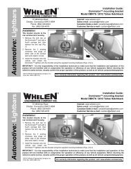
IMPORTANT! It is the responsibility of the installation technician<br />
to make sure that the installation and operation of this product will<br />
not interfere with or compromise the operation or efficiency of any<br />
vehicle equipment!<br />
Routing your Lightbar Cable(s):<br />
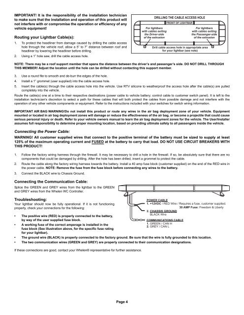
1. To protect the headliner from damage caused by drilling the cable access<br />
hole through the vehicle roof, allow a 5” to 7” distance between roof and<br />
headliner by lowering the headliner before drilling.<br />
2. Using a 1” hole saw, drill the cable access hole.<br />
For lightbars<br />
with cables exiting<br />
the Driver-side<br />
of the extrusion<br />
DRILLING THE CABLE ACCESS HOLE<br />
FRONT OF LIGHTBAR<br />
For lightbars<br />
with cables exiting<br />
the Passenger-side<br />
of the extrusion<br />
Drill cable access hole in appropriate area<br />
for your lightbar (see note)<br />
NOTE: There may be a roof support member that spans the distance between the driver’s and passenger’s side. DO NOT DRILL THROUGH<br />
THIS MEMBER! Adjust the location until the hole can be drilled without contacting this support member.<br />
3. Use a round file to smooth and de-burr the edges of the hole.<br />
4. Install a 1” grommet (user supplied) into the cable access hole.<br />
5. Insert the cable(s) through the cable access hole into the vehicle. Use RTV silicone to weatherproof the access hole after the cable(s) are pulled<br />
completely into the vehicle.<br />
Route the cable(s) one at a time to their respective destinations (power cable to vehicle battery; control cable to customer switch panel). It is left to the<br />
installation technician's discretion to select a path for these cables that will both protect the cables from possible damage and not interfere with the<br />
operation of any other vehicle components or equipment. Refer to the instructions included with your switches for switch wiring information.<br />
IMPORTANT AIR BAG WARNING!Do not install this product or route any wires in the air bag deployment zone of your vehicle. Equipment<br />
mounted or located in air bag deployment zones will damage or reduce the effectiveness of the air bag, or become a projectile that could cause<br />
serious personal injury or death. Refer to your vehicle owners manual to learn the air bag deployment zones for the vehicle. The User/Installer<br />
assumes full responsibility to determine proper mounting location, based on providing ultimate safety to all passengers inside the vehicle.<br />
Connecting the Power Cable:<br />
WARNING! All customer supplied wires that connect to the positive terminal of the battery must be sized to supply at least<br />
125% of the maximum operating current and FUSED at the battery to carry that load. DO NOT USE CIRCUIT BREAKERS WITH<br />
THIS PRODUCT!<br />
1. Follow the factory wiring harness through the firewall. It may be necessary to drill a hole in the firewall. If so, be absolutely sure that there are no<br />
components that could be damaged by drilling. After the hole has been drilled, insert a grommet to protect the cable.<br />
2. Route the cable along the factory wiring harness towards the battery. Install a 40 amp fuse block (customer supplied) on the end of the RED wire in<br />
the power cable. NOTE: Remove the fuse from the fuse block before connecting any wires to the battery.<br />
3. Connect the BLACK wire to Chassis Ground.<br />
Connecting the Communication Cable:<br />
Splice the GREEN and GREY wires from the lightbar to the GREEN<br />
and GREY wires from the <strong>Whelen</strong> WC Controller.<br />
Troubleshooting:<br />
Your lightbar should now be fully operational. If it is not functioning<br />
properly, check your connections for the following:<br />
POWER CABLE<br />
1. +12VDC / RED Wire / Requires a fuse, customer supplied.<br />
30 AMP Fuse: Freedom & Liberty<br />
2. CHASSIS GROUND<br />
• The positive wire (RED) is properly connected to the battery,<br />
by way of the user supplied fuse block.<br />
2. BLACK Wire<br />
COMMUNICATIONS CABLE<br />
• A working fuse of the correct amperage is installed in the<br />
1. GREEN / CAN H<br />
2. GREY / CAN L<br />
fuse block (See illustration above, for the specific fuse rating<br />
for your lightbar).<br />
• The ground wire (BLACK) is properly connected to the factory ground. Be sure that the wire is fully grounded to this location.<br />
• The two communication wires (GREEN and GREY) are properly connected to their communication designations.<br />
If these connections are good, contact your <strong>Whelen</strong>® representative for further assistance.<br />
Page 4