A4021 Series - Honeywell
A4021 Series - Honeywell
A4021 Series - Honeywell

Create successful ePaper yourself
Turn your PDF publications into a flip-book with our unique Google optimized e-Paper software.
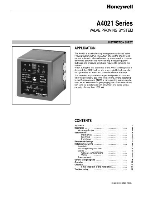
<strong>A4021</strong> <strong>Series</strong><br />
VALVE PROVING SYSTEM<br />
APPLICATION<br />
INSTRUCTION SHEET<br />
The <strong>A4021</strong> is a self--checking microprocessor based Valve<br />
Proving System (VPS). The <strong>A4021</strong> checks the effective closure<br />
of automatic shut--off valves by measuring the pressure<br />
differential between two valves during the test sequence.<br />
Subbase and pressure switch are required to complete the<br />
system.<br />
When during the test sequence of the <strong>A4021</strong> a failing valve is<br />
detected, the <strong>A4021</strong> will go into a non--volatile lock--out status,<br />
generates an alarm and prevents a burner start--up.<br />
The intended application is for gas fired power burners and<br />
other large capacity gas firing installations, where according<br />
to the European norm EN676 a valve proving system can be<br />
used as an alternative for pre--purging the combustion chamber.<br />
And for installations with or without pre--purge with a<br />
capacity of more than 1200 kW.<br />
CONTENTS<br />
Application ....................................... 1<br />
Description ....................................... 2<br />
Working principle ............................. 2<br />
Specifications ..................................... 5<br />
Mechanical ................................ 5<br />
Electrical .................................. 5<br />
Functional ................................. 5<br />
Dimensional drawings ............................... 7<br />
Installation and wiring ............................... 8<br />
Installation .................................. 8<br />
Mounting wiring subbase ...................... 8<br />
Wiring ...................................... 8<br />
General considerations ..................... 8<br />
Wiring .................................... 8<br />
Pressure switch .............................. 8<br />
General wiring diagrams ............................. 8<br />
Operation ........................................ 10<br />
Checkout ......................................... 11<br />
Final checkout of the installation .............. 11<br />
Troubleshooting ................................... 12<br />
EN2C-0030SZ20 R0604
DESCRIPTION<br />
The <strong>A4021</strong> valve proving system checks the effective closure<br />
of the valves before burner start--up (pre--configuration) or at<br />
the end of a heat demand (post--configuration). The<br />
configuration can be set by means of wiring the <strong>A4021</strong> in two<br />
different ways, see Fig. 1. and 2.<br />
The flow chart (Fig. 4. ) and sequence diagram (Fig. 5. )<br />
explain the procedure during the valve proving.<br />
An external pressure switch monitors the pressure between<br />
both valves. The pressure switch must be set to half the inlet<br />
pressure in order to test both valves with the same sensitivity.<br />
After a short interruption of the mains supply during valve<br />
proving or during RUN, the <strong>A4021</strong> restarts automatically.<br />
The <strong>A4021</strong> valve proving system can be used with several<br />
pilot--valve configurations, like intermittent and interrupted<br />
pilot systems and 3--valve configurations as well.<br />
LGPS H.D<br />
L<br />
9<br />
<strong>A4021</strong><br />
14<br />
12<br />
Fig. 1. Valve proving pre--configuration.<br />
LGPS<br />
L<br />
9<br />
<strong>A4021</strong><br />
14<br />
12<br />
H.D<br />
Fig. 2. Valve proving post--configuration.<br />
ignition<br />
controller<br />
ignition<br />
controller<br />
heat<br />
demand<br />
Valve Proving System<br />
<strong>A4021</strong> <strong>Series</strong><br />
burner--controller<br />
7800 SERIES<br />
Gas pressure switches<br />
C6058A <strong>Series</strong><br />
L.G.P.S.<br />
G.P.S.<br />
Pinlet<br />
2<br />
gas<br />
Pinlet<br />
V1<br />
V2<br />
Combi--valve VQ400 <strong>Series</strong><br />
Servo Motor MT4000 <strong>Series</strong><br />
burner<br />
air<br />
Fig. 3. System set--up .<br />
Working principle<br />
The <strong>A4021</strong> valve proving system is based on the pressure<br />
status--principle. This means that the valves are checked by<br />
means of measuring (on/off) the pressure in the gas--pipe<br />
between the two safety--valves. This system will only work<br />
when there is sufficient gas--pressure (line--pressure).<br />
Therefore a Low Gas Pressure Switch (LGPS) is part of the<br />
installation. When the line--pressure (Pinlet) is too low the<br />
LGPS will disable the valve proving system.<br />
The section between the two valves is filled with gas<br />
(high--pressure status) by opening valve--1 (upstream valve)<br />
and the pipe is emptied (low--pressure status) by closing<br />
valve--1 and opening valve--2 (down--stream). When one of<br />
the valves is leaking this will mean that either the pressure<br />
will not maintain the high--pressure status or the low--pressure<br />
status at the end of the test period.<br />
For this method of testing, the test time is a function of three<br />
parameters.<br />
− inlet pressure<br />
− volume between the valves.<br />
− maximum burner capacity.<br />
The test time can be calculated as given in the Product<br />
Handbook. Different test times are available by different O.S.<br />
numbers.<br />
EN2C-0030SZ20 R0604<br />
2
manual reset<br />
STANDBY<br />
start<br />
0<br />
Table 1. Sequence timings for normal operation<br />
State Description Time 1) (s)<br />
0 STANDBY infinite 2)<br />
1 self--test + memory test
Line voltage<br />
Heat demand<br />
Leak test<br />
Valve V1<br />
POST<br />
CONFIG<br />
Valve V2<br />
Vent valve<br />
(normally open)<br />
GPS<br />
Leak test<br />
4 EN2C-0030SZ20 R0604<br />
PRE<br />
CONFIG<br />
Valve V1<br />
Valve V2<br />
Vent valve<br />
(normally open)<br />
GPS<br />
Lock--out<br />
(Ignition controller)<br />
Reset ign. control.<br />
power--up<br />
start<br />
heat--demand<br />
end<br />
heat--demand<br />
start<br />
heat--demand<br />
Fig. 5. System sequence with <strong>A4021</strong>A in post and pre--configuration.<br />
lock--out<br />
reset burner controller<br />
start whithout valve proving !
SPECIFICATIONS<br />
Mechanical<br />
Model<br />
<strong>A4021</strong>A<br />
Dimensions<br />
Refer to Fig. 6.<br />
For mounting bracket dimensions refer to Fig. 7.<br />
Weight<br />
Including subbase: 0.65 Kg<br />
Mounting<br />
ZL030001 subbase.<br />
The subbase can be assembled by 2 screws on a panel.The<br />
cover can be removed by loosening one screw. For mounting<br />
hole dimensions see Fig. 6. installation drawing.<br />
Orientation<br />
There are no restrictions in the orientation.<br />
Environmental ratings<br />
Ambient temperature range:<br />
Operating :--10 ... 60 °C<br />
Storage :--40 ... 80 °C<br />
Humidity: :0 -- 95% RH at 40 °C (non--condensing)<br />
Vibration :0.5 G environment<br />
Electrical<br />
Supply voltage<br />
Line voltage:<br />
220 ... 240 Vac, 50 Hz<br />
100 ... 120 Vac, 50 Hz<br />
Refer to Table 2.<br />
Other voltage ranges and frequencies are available on<br />
request.<br />
Fusing<br />
The <strong>A4021</strong>A should be externally fused to prevent damage to<br />
the valve proving system, wiring or peripherals<br />
External fuse: 16 A slow max.<br />
Internal fuse: 5 A slow max.<br />
Power consumption<br />
Maximum 4.5 VA<br />
Electrical ratings<br />
Valve outputs: 4A, cos. ϕ 0.7<br />
Vent valve output: 1A, cos. ϕ 0.7<br />
Ignition controller output: 4A, cos. ϕ0.7<br />
Alarm output: 2A, cos. ϕ 0.7<br />
Electrical connection<br />
4WiringconduitaccordingtoPG11areprovidedinthe<br />
subbase. M3.5 screw terminals, including earth connection.<br />
Enclosure<br />
IP40<br />
Functional<br />
Field adjustments (calibration)<br />
None<br />
Test--times<br />
Depending on O.S. number.<br />
For <strong>A4021</strong>A1002 and <strong>A4021</strong>A1010 per valve: 25 s.<br />
Other test times available on request.<br />
Total test--time (depending on test time per valve)<br />
For model <strong>A4021</strong>002 and <strong>A4021</strong>A1010: approx. 65 seconds<br />
Reset<br />
NON--volatile lock--out<br />
Manual, with push--button on controller or with remote reset<br />
button.<br />
Design life<br />
> 10 years or 250.000 cycles.<br />
Recommended pressure switch<br />
C6058A gas pressure switch<br />
Standards and Approvals (summarized)<br />
The <strong>A4021</strong>A <strong>Series</strong> Valve Proving System is conform with the<br />
following EC directives:<br />
• Gas Appliance Directive (90/396/EEC)<br />
PIN: CE--0063AS1822<br />
• Low Voltage Directive (73/23/EEC)<br />
• Electro Magnetic Compatibility Directive (89/336/EEC)<br />
5<br />
EN2C-0030SZ20 R0604
Table 2. Connections for <strong>A4021</strong>A pre-- and post--configuration with contact ratings.<br />
Terminal Abbreviations Direction Description Ratings<br />
No.<br />
(220 ... 240Vac/100 ... 120Vac,<br />
pre post<br />
depending on O.S. number)<br />
1 NO NO input Normally Open contact of the pressure<br />
n.a.<br />
switch (high pressure)<br />
2 RESET RESET input Input for external reset connect with<br />
n.a.<br />
momentary switch to line<br />
3 LINE LINE power--input Line voltage input for valve proving<br />
n.a.<br />
system.<br />
4 N N power--input Neutral input for valve proving system. n.a.<br />
5 N N power Neutral for external devices. n.a.<br />
6 N N power Neutral for external devices. n.a.<br />
7 V2--IN V2--IN input Valve--2 voltage from ignition controller n.a.<br />
8 V2--OUT V2--OUT output Output connect with Valve--2 4A<br />
9 HD LGPS input Heat--demand input (pre--configuration)<br />
n.a.<br />
or LGPS input (post--configuration)<br />
10 ALARM ALARM input Alarm input 4A<br />
11 ALARM ALARM output Alarm output 2A<br />
12 RB RB input Read back signal for: heat--demand<br />
4A<br />
(post-- config.) ign. contr. (pre--config.)<br />
13 VENT VENT output Normally open valve output 1A<br />
14 IGNCTR HD output Heat call signal to ignition controller,<br />
4A<br />
when there is a heat call and the valve<br />
proving has taken place<br />
15 V1--IN V1--IN input Valve--1 voltage from ignition controller 2A<br />
16 V1--OUT V1--OUT output Output connect with Valve--1 4A<br />
NOTE:<br />
cos. ϕ = 0.7 for all outputs<br />
EN2C-0030SZ20 R0604 6
DIMENSIONAL DRAWINGS<br />
88<br />
35<br />
16<br />
97<br />
1 2 3 4 5 6 7 8<br />
97<br />
PG11<br />
9 10 11 12 13 14 15 16<br />
Fig. 6. Mounting dimensions of <strong>A4021</strong>A and subbase in millimeters<br />
103<br />
∅ 4.5 (4x)<br />
90°<br />
3<br />
86.5<br />
60.5<br />
34.5<br />
∅ 20<br />
52<br />
80<br />
96<br />
8.5<br />
69<br />
74.5<br />
80<br />
96<br />
Fig. 7. Mounting bracket <strong>A4021</strong>A for VQ400 and VE5000 <strong>Series</strong> in millimeters<br />
7<br />
EN2C-0030SZ20 R0604
INSTALLATION AND WIRING<br />
Installation<br />
IMPORTANT<br />
Read these instructions carefully. Failure to follow<br />
the intructions could damage the product or<br />
cause a hazardous condition.<br />
1. Before installing or replacing any control check<br />
that the test time is correct for the application.<br />
Neveruseatypewithasmallertesttimethanthe<br />
calculated test time for the application.<br />
Check the ratings given in the instructions and on<br />
the product to make sure the product is suitable<br />
foryourapplication.<br />
2. The installation has to be carried out by qualified<br />
personel only.<br />
3. Carry out a thorough checkout when installation<br />
is completed.<br />
Mounting wiring subbase<br />
NOTE: For installation dimensions, see Fig. 6.<br />
1. The subbase can be mounted in any position. Make<br />
sure that the LEDs indicating the test sequence and<br />
faults--causes are clearly visible.<br />
2. Select a location within an electrical panel. Be sure to<br />
allow adequate clearance for servicing, installation and<br />
electrical field connections.<br />
3. For surface mounting, use the back of the subbase as a<br />
template to mark the two screw locations. Drill the pilot<br />
holes.<br />
4. Securely mount the subbase using two M3.5 x 0.6<br />
screws.<br />
Wiring<br />
CAUTION<br />
1. Disconnect power supply before beginning the<br />
installation to prevent electrical shock, equipment<br />
and control damage. More than one power supply<br />
disconnect may be involved.<br />
2. Wiring connections are for the <strong>A4021</strong>A are<br />
unique, therefore, refer to Table 2. and Fig. 6. for<br />
proper subbase wiring.<br />
3. The <strong>A4021</strong>A must be installed with fixed wiring for<br />
phase and neutral connections.<br />
4. Wiring must comply with all applicable codes,<br />
ordiances and regualtions.<br />
5. After moving the <strong>A4021</strong>A valve proving system<br />
from outdoor to indoor conditions, condensation<br />
may occur. Do not connect condensated valve<br />
proving system to mains.<br />
6. The <strong>A4021</strong>A is not suitable for phase--phase<br />
mains., can only be used with phase -- neutral<br />
mains.<br />
7. For each application diagram, local approval may<br />
be needed<br />
General considerations<br />
There are two basic wiring diagrams:<br />
• valve proving before burner start--up: pre--configuration.<br />
• valve proving at end of heat demand: post--configuration.<br />
Wiring<br />
1. For proper subbase wiring, refer to Table 2.<br />
2. Disconnect the power supply from the main disconnect<br />
before beginning the installation to prevent electrical<br />
shock and equipment damage. More than one<br />
disconnect may be involved.<br />
3. All wiring must comply with all applicable electrical<br />
codes, ordnances and regulations.<br />
4. Use the COM and NO contacts on both pressure<br />
switches (LGPS and GPS).<br />
5. Make sure loads do not exceed the terminal ratings.<br />
refer to the label on the valve proving system, or to the<br />
ratings in the Specifications, see Table 2.<br />
6. Check the power supply circuit. the voltage and<br />
frequency tolerance must match those of the valve<br />
proving system. Add the required disconnect means<br />
and overload protection.<br />
7. Check all wiring circuits before installing the valve<br />
proving system on the subbase<br />
8. Install all electrical connectors.<br />
9. Restore power to the panel.<br />
Pressure switch<br />
The pressure switch can be a normal normally open gas<br />
pressure switch which is suitable for the appropriate pressure<br />
levels and a voltage of 220 ... 240 Vac. Refer to the enclosed<br />
instructions of the pressure switch. The switching point of the<br />
GPS must be at 50 % of the nominal line--pressure.<br />
Recommended gas pressure switch: C6058A<br />
GENERAL WIRING DIAGRAMS<br />
N<br />
L<br />
fuse<br />
16A<br />
T<br />
N<br />
4(N)<br />
Ignition controller<br />
9<br />
L<br />
LGPS<br />
V1<br />
heat--demand<br />
input<br />
reset (ext.)<br />
GPS<br />
V2<br />
main--valve<br />
output<br />
ALARM<br />
3 2 14 12 15 7 10<br />
Valve Proving System<br />
11<br />
<strong>A4021</strong>A<br />
6(N)<br />
16 1 5(N) 8 13<br />
Fig. 8. Wiring diagram for 2--valve configuration<br />
pre--configuration<br />
vent--valve<br />
EN2C-0030SZ20 R0604 8
N<br />
L<br />
Ignition controller<br />
heat--demand<br />
input<br />
main--valve<br />
output<br />
N<br />
L<br />
Ignition controller<br />
pilot<br />
heat--demand valve<br />
input output<br />
main<br />
valve<br />
output<br />
N<br />
reset (ext.)<br />
T<br />
N<br />
reset<br />
(ext.)<br />
T<br />
L<br />
fuse<br />
16A<br />
4(N)<br />
9<br />
3<br />
2 14 12 15 7 10<br />
Valve Proving System<br />
11<br />
<strong>A4021</strong>A<br />
6(N)<br />
16 1 5(N) 8 13<br />
ALARM<br />
L<br />
fuse<br />
16A<br />
4(N)<br />
9<br />
3<br />
2 14 12 15 710<br />
Valve Proving System<br />
11<br />
<strong>A4021</strong>A<br />
6(N)<br />
16 1 5(N) 8 13<br />
ALARM<br />
V1<br />
V2<br />
vent--valve<br />
V1<br />
V2<br />
vent--valve<br />
LGPS<br />
GPS<br />
LGPS<br />
GPS<br />
Fig. 9. Wiring diagram 2--valve configuration for<br />
post--configuration<br />
Vp<br />
N<br />
Ignition controller<br />
L<br />
heat--demand<br />
input<br />
pilot<br />
valve<br />
output<br />
main<br />
valve<br />
output<br />
Fig. 11. Wiring diagram 3--valve configuration<br />
(post--configuration)<br />
N<br />
reset (ext.)<br />
L<br />
fuse<br />
16A<br />
4(N)<br />
9<br />
3<br />
2 14 12 15 7 10<br />
Valve Proving System<br />
11<br />
<strong>A4021</strong>A<br />
6(N)<br />
16 1 5(N) 8 13<br />
ALARM<br />
T<br />
V1<br />
V2<br />
vent--valve<br />
LGPS<br />
GPS<br />
Vp<br />
Fig. 10. wiring diagram 3--valve configuration<br />
(pre--configuration)<br />
!<br />
WARNING<br />
These are general wiring diagram and have not been<br />
approved yet by an official approval body. Depending<br />
on the application and used ignition controller special<br />
wiring diagrams maybe required.<br />
9<br />
EN2C-0030SZ20 R0604
Modes<br />
Timings (sec.)<br />
*= depends on OS #<br />
Heat demand<br />
Pressure<br />
(between V1 and V2<br />
TEST MODE<br />
25 * 25 *<br />
5* 3* 5* 3*<br />
RUN MODE<br />
ALARM MODE<br />
States 0 1 2 3 4 5 6 7 8 9 10 11 12 13 14 15<br />
Line voltage<br />
STANDBY<br />
Sequence of operation<br />
OPERATION<br />
Valve 1<br />
Valve 2<br />
Operate burner<br />
10 EN2C-0030SZ20 R0604<br />
Alarm output<br />
Power<br />
Run<br />
Alarm<br />
Valve 1<br />
Valve 2<br />
!<br />
OK<br />
STANDBY<br />
WARNING<br />
START OPEN TEST TEST OPEN TEST TEST<br />
SELF V2 GPS V1<br />
V1 GPS V2<br />
TEST<br />
LOW<br />
No standard valve proving after lock--out of the ignition controller<br />
HIGH<br />
WAIT OPERATE<br />
FOR BURNER<br />
(valves operated by<br />
START--UP<br />
ignition controller)<br />
ERROR<br />
V2<br />
FAILING/ ERROR FAILING/ ERROR ERROR<br />
LEAKING V1 LEAKING HEAT SELF--<br />
V1<br />
V2<br />
DEMAND TEST<br />
= LED is off = blinking LED<br />
= LED on
CHECKOUT<br />
The procedures described in this chapter are related to<br />
<strong>A4021</strong>A. For adjustments on the other additional<br />
functionalities (e.g. pressure switch), refer to the included<br />
instruction sheet of the product in question in the package.<br />
WARNING<br />
Phase -- neutral dependency<br />
As the EARTH is not connected to the actual <strong>A4021</strong>A<br />
(earth only connected to the sub--base), it is not<br />
possible to detect whether the line and neutral are<br />
correct connected on the <strong>A4021</strong>A.<br />
Exchanged connection of the phase and neutral can<br />
lead to hazardous situations, when a short--circuit in<br />
one of the valve connections occurs. Therefore the<br />
<strong>A4021</strong>A can only be used with fixed wiring for the<br />
line--voltage connections. Make sure that phase and<br />
neutral are connected as instructed in the Wiring<br />
section.<br />
Final checkout of the installation<br />
Set the appliance in operation after any adjustment and<br />
observe several complete cycles to ensure that all burner<br />
components function correctly.<br />
Make sure that phase and neutral are connected as<br />
instructed in the Wiring section.<br />
11 EN2C-0030SZ20 R0604
TROUBLESHOOTING<br />
CAUTION<br />
1. Use utmost care while troubleshooting the<br />
<strong>A4021</strong>A, line voltage is present on some of the<br />
terminals when power is on.<br />
2. Line voltage is present on the terminals when the<br />
cover is removed. Make sure that the main power<br />
supply is switched off before removing the cover.<br />
3. The <strong>A4021</strong>A contains no serviceable parts. Any<br />
attempt or replacement of parts ( except from<br />
internal fuse) will affect the safety of this<br />
deviceand is therefor not allowed.<br />
General<br />
If you encounter a error or fail on V1 or V2, refer to the<br />
instruction sheet of the valve.<br />
If you encounter other problems in the system, refer to the<br />
Troubleshooting section in the instruction sheet for the<br />
appropriate flame safeguard control.<br />
Upon completion of troubleshooting, be sure to perform the<br />
Checkout procedures previously specified for the <strong>A4021</strong>A.<br />
NOTE:<br />
Table 3. Troubleshooting <strong>A4021</strong>A<br />
Instructions for replacing the cover and fuse are<br />
givenintheServicesection.<br />
Before making a replacement, make sure you have the<br />
correct part (check its part number and voltage rating)<br />
States PWR RUN ALARM V1 V2<br />
OK<br />
Alarm mode Cause Action<br />
10 Error V2 V2 is damaged or V2 is<br />
wrong/not connected<br />
11 Failing/leaking V1 Allowed leak--rate (V1)<br />
higher than 0.1% of the<br />
maximum flow--rate<br />
12 Error V1 V1 is damaged or V1 is<br />
wrong/not connected<br />
13 Failing/leaking V2 Allowed leak--rate (V2)<br />
higher than 0.1% of the<br />
maximum flow--rate<br />
14 Error heat demand<br />
Heat demand read--back<br />
error .<br />
15 Error self--test Internal Hardware/Software<br />
error<br />
Check connections V2 and<br />
if necessary replace V2<br />
Check the gas pressure<br />
switch (GPS) and if needed<br />
replace V1<br />
Check connections V1 and<br />
if necessary replace V1<br />
Check gas pressure switch<br />
(GPS) and if needed<br />
replace V2<br />
Check if pin 12 on <strong>A4021</strong>A<br />
is connected<br />
Reset main supply, reset<br />
<strong>A4021</strong>A; if error still occurs:<br />
replace <strong>A4021</strong>A<br />
= LED is off = blinking LED<br />
= LED on<br />
Automation & Control Solutions<br />
Control Product<br />
Satronic AG<br />
<strong>Honeywell</strong>-Platz 1<br />
CH-8157 Dielsdorf<br />
Phone: +41 1 855 22 11<br />
Fax: +41 1 855 22 22<br />
EN2C-0030SZ20 R0604 12