Untitled - ESMA, Inc.
Untitled - ESMA, Inc.
Untitled - ESMA, Inc.

Create successful ePaper yourself
Turn your PDF publications into a flip-book with our unique Google optimized e-Paper software.
Esma <strong>Inc</strong>.<br />
PO Box 734 450 W. Taft Drive<br />
South Holland, IL 60473<br />
708-331-1855 800-276-2466 FAX 708-331-8919<br />
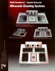
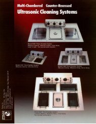
Introduction<br />
Instructions for<br />
Model E782<br />
Betman Cleaning System<br />
(Cleaner/Rinser/Rinser/Dryer)<br />
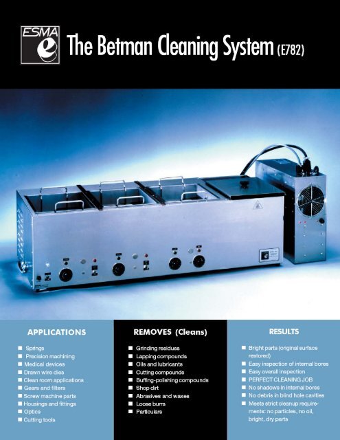
The Model E782 Cleaning system contains 1 ultrasonic cleaning tank, 2 ultrasonic rinse<br />
tanks and a hot air drying chamber. Each ultrasonic tank and the drying tank have<br />
separate control timers. The ultrasonic tanks are supplied with heaters controlled with<br />
internal, adjustable thermostats.<br />
Tanks 2-3 are ultrasonic rinse tanks. Fresh rinse water can be introduced into the<br />
system with the excess cascading to drain.<br />
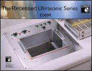
The E782 unit consists of two components: the main cleaning unit containing the 316<br />
Stainless Steel tanks housed in a 304 stainless cabinet and a stainless power module<br />
cabinet containing the bulk of the electronics.<br />
Each tank has 6 potting transducers mounted on the bottom and is equipped with a ball<br />
valve for draining.<br />
The Power Module contains self-tuning modular circuit boards, high velocity fans to<br />
cool the electronics, and an RFI filter to eliminate high frequency noise feedback.<br />
PLEASE READ THESE INSTRUCTIONS BEFORE INSTALLATION AND OPERATION. If there<br />
are any questions, call (800) 276-2466.<br />
INSTALLATION<br />
Place unit on a bench close to a sink or drain. The power module can be placed up to 8<br />
feet away from tank, either on a shelf or in a cabinet.<br />
The power module should not be positioned where it can be splashed with liquids,<br />
where it can attract dirt or abrasives, or where the air cooling by the fan can be<br />
restricted because of tight enclosures. Clearance of 1” is necessary both at the air<br />
intake and exhaust.<br />
3
PLUMBING<br />
A number of valves and connectors have been supplied with unit. With the PVC and<br />
plastic fittings and valves, add Teflon tape to the threads and HAND tighten. (DON’T<br />
OVERTIGHTEN)<br />
1. Three ball valves are supplied. Add Teflon tape and thread a ball valve into the<br />
drain port of each tank. A ¼” NPT x ½” hose connector is to be added to the<br />
outlet of each ball valve.<br />
2. Connect your water source to the rinse inlet of tank 3. A needle valve is<br />
supplied to regulate the water flow into the tank. An internal solenoid starts or<br />
stops the flow in conjunction with the timer. Connect your water supply to the<br />
¼” compression input of the needle valve.<br />
3. Add ¼” NPT x ½” hose connector to the rinse outlet port of tank 3 and connect a<br />
hose to drain. When operating, turn timer 3 ON and water comes in tank and<br />
cascades out to drain.<br />
4. Tank 3 also has a high level sensor. If the water level becomes too high in tank<br />
because of a blockage in the drain line, the sensor will shut off this solenoid<br />
preventing any water overflow of tank.<br />
Before starting, add water manually to the ultrasonic tanks so that the ultrasonics do<br />
not run on an empty tank.<br />
ELECTRICAL<br />
The unit has two power cords that are plugged into the 120VAC, 50/60HZ source. The<br />
POWER MODULE is rated at 2550 watts, 120vac. Two plug and cord assemblies from<br />
tank cabinet are plugged into power module. A fuse, 25amp-125V, is located on the<br />
power module cabinet.<br />
A separate power cord from tank cabinet is rated at 1550 watts, 120VAC<br />
50/60HZ. The power cord supplies power to the tank heaters. A 15amp-125V fuse is<br />
located on the front of the tank cabinet.<br />
OPERATION<br />
The MAIN switch on power module is left ON during daily operation.<br />
Parts to be cleaned are placed in rack (basket) and rack is positioned into the tanks.<br />
Never place parts directly on bottom tank (tank could eventually be perforated). The<br />
basic principle of operation is the enhancement and acceleration of the chemical<br />
cleaning by ultrasonic action.<br />
4
1. Heater – The tanks are supplied with 400 watts of heat controlled by an<br />
adjustable, internal thermo switch. The thermo switch has been adjusted to<br />
control the bath temperature at 160degrees F when tank covers are on. If<br />
temperature needs to be changed, there is a port at the rear of each tank<br />
module where a screwdriver can be used to adjust the control knob of<br />
thermostat. The thermostat is the same as used in the drying chamber<br />
mentioned below. Use the same procedure for adjusting the temperature but<br />
use caution that the bath temperature does not exceed 180 degrees F.<br />
CAUTION – Before adjusting thermostat turn power OFF.<br />
2. Timer – Digital solid state timers have been installed in the unit. (See<br />
separate instructions). Simply set the time with the ↑ or ↓ button.<br />
After time has been set, push START-STOP button and ultrasonic<br />
cleaning/rinsing or hot air drying will commence for the set time. The<br />
cycle can be stopped at any time by momentarily turning the main switch<br />
OFF. An alarm will sound when the time has expired and the timer will<br />
return to the set time setting. Press and hold the START-STOP button at any<br />
time for to return the timer to the set time.<br />
3. Drying Chamber – The drying chamber uses forced hot air thermostatically<br />
controlled at 160 degrees-180 degrees F. (set by the manufacturer) Drying time<br />
will vary depending on the number of parts to be dried, if hot or cold water was<br />
used to rinse parts before drying and if the cover is on oven. Generally parts<br />
should be dry in 10 minutes.<br />
CAUTION: Parts after drying will be hot (170 degrees F) and should be cooled<br />
before touching.<br />
The air temperature of the dryer has been set at the factory to reach 170degrees F with<br />
cover on the oven. If you want to change the temperature, there is a thermostat<br />
mounted above blower in closed chamber behind oven. The temperature can be<br />
changed as follows:<br />
1. Disconnect unit from 120V outlet.<br />
2. There is a port at rear of dryer module<br />
where a screw driver can be inserted to<br />
adjust the temperature.<br />
3. Move control knob of thermostat slightly<br />
in clockwise direction to increase<br />
temperature and counter-clockwise to decrease temperature. Make only<br />
slight changes because a 30 degree angle change corresponds to an<br />
approximate 20 degrees F temperature change. Replace top plate on<br />
chamber.<br />
5
MAINTENANCE<br />
Periodically, the liquid in tanks must be changed:<br />
• Unplug the unit from 120VAC outlet.<br />
• Open ball valve at back of tank chamber to drain.<br />
• Flush out tank with clean water and wipe dry.<br />
• Close ball valve and add fresh solution.<br />
Keep top of unit dry. Unit is manufactured from 304 stainless and can be restored to<br />
the original finish with a stainless polish used for kitchen appliances.<br />
MODULAR CIRCUIT BOARD<br />
Unit E782 is equipped with three modular circuit boards that are easily replaced if a<br />
problem occurs. Three small indicator lights on the power module indicate that circuit<br />
boards are working. If the indicator light goes out, a replacement circuit board can be<br />
shipped immediately. This way the need for shipping the unit back for repairs is<br />
eliminated and the disruption is minimal.<br />
WARRANTY<br />
The unit has a one year warranty, two year warranty on circuit boards and lifetime<br />
warranty on tank weld seams and transducer bonds.<br />
CALL 1-800-276-2466 FOR TECHNICAL SERVICE.<br />
6