SAFACTIVE FILTER - COMAR CONDENSATORI SpA
SAFACTIVE FILTER - COMAR CONDENSATORI SpA
SAFACTIVE FILTER - COMAR CONDENSATORI SpA

Create successful ePaper yourself
Turn your PDF publications into a flip-book with our unique Google optimized e-Paper software.
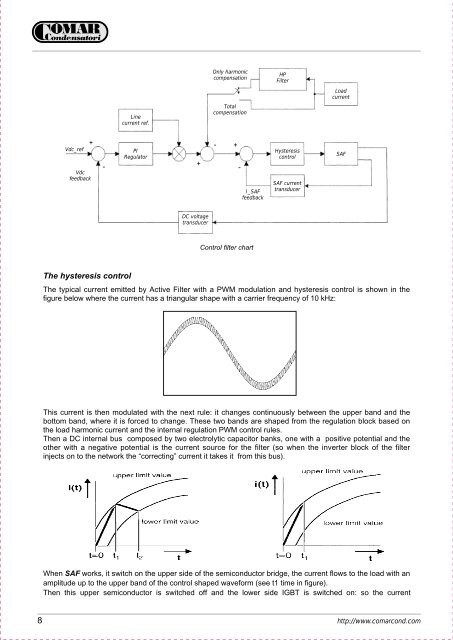
Only harmonic<br />
compensation<br />
HP<br />
Filter<br />
Load<br />
current<br />
Line<br />
current ref.<br />
Total<br />
compensation<br />
Vdc_ref<br />
+<br />
Vdc<br />
feedback<br />
–<br />
PI<br />
Regulator<br />
+<br />
– +<br />
–<br />
I_SAF<br />
feedback<br />
Hysteresis<br />
control<br />
SAF current<br />
transducer<br />
SAF<br />
DC voltage<br />
transducer<br />
Control filter chart<br />
The hysteresis control<br />
The typical current emitted by Active Filter with a PWM modulation and hysteresis control is shown in the<br />
figure below where the current has a triangular shape with a carrier frequency of 10 kHz:<br />
This current is then modulated with the next rule: it changes continuously between the upper band and the<br />
bottom band, where it is forced to change. These two bands are shaped from the regulation block based on<br />
the load harmonic current and the internal regulation PWM control rules.<br />
Then a DC internal bus composed by two electrolytic capacitor banks, one with a positive potential and the<br />
other with a negative potential is the current source for the filter (so when the inverter block of the filter<br />
injects on to the network the “correcting” current it takes it from this bus).<br />
When SAF works, it switch on the upper side of the semiconductor bridge, the current flows to the load with an<br />
amplitude up to the upper band of the control shaped waveform (see t1 time in figure).<br />
Then this upper semiconductor is switched off and the lower side IGBT is switched on: so the current<br />
8 http://www.comarcond.com