SAFACTIVE FILTER - COMAR CONDENSATORI SpA
SAFACTIVE FILTER - COMAR CONDENSATORI SpA
SAFACTIVE FILTER - COMAR CONDENSATORI SpA

Create successful ePaper yourself
Turn your PDF publications into a flip-book with our unique Google optimized e-Paper software.
UNI EN ISO 9001:2000<br />
C<br />
E<br />
R<br />
T<br />
I<br />
F<br />
MANAGEMENT<br />
I<br />
E<br />
D<br />
SYSTEM<br />
ec<br />
UNI EN ISO 14001<br />
H&S<br />
OH SAS 18001<br />
SAF ACTIVE <strong>FILTER</strong>
Shunt active filters for<br />
active compensation of<br />
harmonic currents<br />
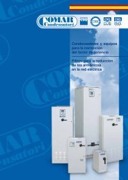
The <strong>COMAR</strong> factory, established in 1968, was built with the future in<br />
mind. By installing superior equipment the factory has remained<br />
technologically advanced even by to-day’s standards. Originally, the<br />
production was based on a wide range of “oil-paper” capacitors. The<br />
quality of the product was such that the <strong>COMAR</strong> brand was soon<br />
acknowledged both in Italy and world wide. A large investment in<br />
research and development during this early period made it possible<br />
to commence production of the innovative metallized polypropylene<br />
film capacitors. The capacitors became part of the standard range in<br />
the 1972 and are still produced by all the main manufactures in the<br />
capacitors market. In the following years, the range was enlarged by<br />
addition of electrolytic capacitors and capacitors specifically for power<br />
electronics. Power factor correction equipment and power factor<br />
regulators were also developed in this period.<br />
Within recent years, because of the diffusion of static power converters,<br />
<strong>COMAR</strong> has examined and resolved the intricate problems of reactive<br />
compensation presented by harmonics. Their study of this subject<br />
has been so successful that <strong>COMAR</strong> is on of the leaders in this very<br />
demanding field. At present, due to the complete automation of all<br />
production lines and advanced test equipment it has been possible<br />
to increase production and improve the level of quality. This is <strong>COMAR</strong>.<br />
UNI EN ISO 9001 quality management system<br />
UNI EN ISO 9001:2000<br />
ec<br />
UNI EN ISO 14001<br />
UNI EN ISO 14001 enviromental management system<br />
H&S<br />
OH SAS 18001<br />
OHSAS 18001 occupational health and safety<br />
management system<br />
Products listed in the present catalogue are in conformity with:<br />
73/23/EEC Low voltage Directive, 89/336 Electro-Magnetic<br />
Compatibility and 93/68EEC Directive.
Index<br />
• Introduction ........................................................................................................................ 4<br />
• Why filtering ....................................................................................................................... 4<br />
• Operatine mode ................................................................................................................. 6<br />
• The hysteresis control ........................................................................................................ 8<br />
• SAF interface ..................................................................................................................... 9<br />
• Led interface .................................................................................................................. 10<br />
• Active filter performances ............................................................................................... 10<br />
• Sizing SAF ..................................................................................................................... 11<br />
• Connection of SAF ......................................................................................................... 12<br />
• The SAF system............................................................................................................. 13<br />
• SAF features .................................................................................................................. 14<br />
http://www.comarcond.com<br />
3
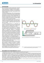
Introduction<br />
In the last twenty years the fast introduction on the market of electronic equipment has brought along with<br />
their advantages many problems due to the noise on the electrical distribution network. In particular the most<br />
dangerous phenomena that degrades the power quality is the presence of harmonic currents generated by<br />
these non linear loads that are continuously changing their impedance during their working cycle, the<br />
absorption of current from the mains is not perfectly sinusoidal at the fundamental frequency, but is a sum of<br />
current with a different frequency multiple of the fundamental.<br />
Why Filtering<br />
These loads can cause many problems to the network and to the other loads connected. Here below is a list<br />
of some types of load that can generate harmonic pollution in the installation during our normal working day:<br />
‣ personal computers<br />
‣ welders<br />
‣ UPS<br />
‣ lifts/elevators<br />
‣ printers<br />
‣ motor speed regulator (AC and DC)<br />
‣ rectifier<br />
‣ semiconductor system with angle regulator<br />
‣ fluorescent lamps with ballasts<br />
‣ SMPS<br />
‣ frequency regulator<br />
Some of this equipment if considered alone does not have a large impact on the installation, but the<br />
influence they have on the network and the other loads connected to it became very important and can<br />
cause serious problems to the integrity of the network.<br />
Then other particular loads that work in critical conditions such as medical equipment (X-ray machinery,<br />
magnetic resonance equipment, etc.) not only can generate harmonic distortion in large amounts, but also<br />
they introduce harmonic pollution in an intermittent manner whilst rapidly changing their working conditions<br />
during a cycle of operation.<br />
So the harmonic currents generated by this load causes great problems and it is important to eliminate them<br />
not only for the immediate effects but also for the problem that can arise in the machinery, other equipment<br />
and the installation.<br />
Many problems can be caused by harmonics, the most common are:<br />
‣ vibration of motors<br />
‣ overheating of the cables<br />
‣ tripping of protective devices<br />
4 http://www.comarcond.com
The presence of harmonic current in the installation can be a large problem because while the<br />
equipment works coupled with the impedance network, it creates also voltage distortion: this distortion<br />
can have a so high level to introduce problems with the other connected equipments in the installation as<br />
in example:<br />
‣ vibration and overheating on the electric motors<br />
‣ noise and loss in the transformers<br />
‣ shortened life of components and conductors in the installation<br />
‣ erratic working of the control circuits that synchronize to the zero-crossing point of the sine wave.<br />
In fact there could be errors in reading the synchronizing signal<br />
‣ voltage difference between the neutral conductor and the protective conductor ( Ground / Earth )<br />
‣ voltage fluctuation of the supply system<br />
‣ erratic operation of voltage or phase loss monitoring equipment<br />
Typical absorption current by a non linear load<br />
Then we have to consider the penalties that the electrical distribution companies charge to their customers<br />
for bad power factor correction due to harmonics.<br />
In order to solve all these problems in accordance with international regulations, the usually adopted<br />
standard is IEEE519 “Recommended Practices and Requirements for Harmonic Control in Electric Power<br />
System” this attempts to establish reasonable harmonic goals for an electrical system that contains non<br />
linear loads to satisfy both customer and distribution company requirements.<br />
The objective is to propose steady-state harmonic limits that are considered reasonable both for electrical<br />
utilities and their customers.<br />
The underlying philosophy is that the customer should limit harmonic currents; electrical utilities should limit<br />
harmonic voltage and both parties share the responsibility for holding harmonic level in check avoiding faults<br />
in installations and loads.<br />
To eliminate harmonic current a passive filter can be used. They are efficient but are also not suitable for<br />
some applications where their characteristics don’t exactly match the requirements:<br />
‣ the filter is difficult to dimension<br />
‣ when a change occurs in the filtered installation (for example: it could be necessary to connect a<br />
new machinery or to substitute an old one with new electrical features) the filter has to be changed<br />
‣ it has partial filtering<br />
‣ it has a very slow dynamic response, so it is not responsive to fast load variation<br />
‣ it’s easy to overload<br />
‣ there’s risk of electrical oscillation with the network impedance<br />
‣ the efficiency depends from the voltage network quality (harmonic voltage distortion)<br />
To overcome these growing technical problems Comar Condensatori S.p.A. has developed SAF, a new<br />
innovative active filter designed to eliminate the harmonic distortion phenomena due to industrial non linear<br />
loads (by its filtering action) and at the same time compensate the reactive power demand of the load (power<br />
factor correction) bringing the installation emission within the recommended levels of IEEE519.<br />
SAF is designed to correct latest generation electronic load harmonic problems.<br />
http://www.comarcond.com<br />
5
So:<br />
‣ it recognizes and compensates all the current up to the 50 th harmonic order<br />
‣ it has excellent dynamic response to fast load variation<br />
‣ it compensates if network features change due to new machinery or equipment in the installation<br />
‣ it is impossible to overload<br />
‣ it’s easy to size<br />
‣ every module is easily connected<br />
‣ it fits every kind of load so it will not be obsolete<br />
These good performance of SAF, with the possibility to connect it to existing an installation and its<br />
modular design allows the filter to give the right solution for every problem with harmonic pollution,<br />
in every kind of condition.<br />
Current from a non linear load (top)<br />
and his relative filtered current (bottom)<br />
Operating mode<br />
The active filter is based on “compensation”, that means that in order to eliminate in a three phase<br />
system the harmonic current absorbed by the non linear load, the filter from the current of the load,<br />
calculates and injects the same harmonics (over the fundamental) shifted by 180 degrees. It results in a<br />
complete elimination from the installation of the dangerous component of the current.<br />
Figure 1<br />
LOAD<br />
Active Filter operation scheme<br />
At the same way it is possible to have a power factor correction of the load, producing three sinusoidal shaped<br />
current waveforms, with an amplitude in line with the load.<br />
In order to understand how SAF operates, look at the picture below there are three different blocks, each one<br />
showing different operating stages of the Active Filter:<br />
6 http://www.comarcond.com
Active Filter block schematic<br />
• Input block, it has:<br />
- Main break switch; fuses;<br />
- EMC filter;<br />
- contactor;<br />
- pre-charge circuit for electrolytic capacitors ;<br />
- line filter;<br />
The main break switch with automatic turn-off and the pre-charge relay, allows the filter to turn-off<br />
and completely disconnect from the network when a internal fault occurs. So that an internal<br />
malfunction of the SAF (i.e. capacitor / microprocessor etc.) doesn’t damage the installation.<br />
To guarantee rapid protection of the input line, the filter is connected with ultra-fast fuses. This<br />
protects the line from every internal problem such as short-circuit, overload, etc. Then the input filter<br />
avoids the emission of harmonic current at the switching frequency of the inverter bridge.<br />
• Inverter block it has:<br />
- semiconductor;<br />
- induction coil;<br />
- electrolytic capacitors;<br />
- heatsink;<br />
- fan;<br />
- power board;<br />
It’s the heart of the power module of SAF.<br />
It can be see as the actuator of the regulator block; in fact it converts the current set point (analog<br />
signal with low power given by the regulation, calculated from the load current) in a current that is in<br />
real time the same as the load harmonic current but 180 degree shifted.<br />
It is established by a typical six-switch semiconductor structure, IGBT technology based, with three<br />
smoothing induction coils and an electrolytic capacitor bank for the DC bus voltage.<br />
• The regulation, it has:<br />
- Microprocessor board<br />
With the regulation based on the hysteresis control, the active filter designed by Comar Condensatori<br />
S.p.A. adapts in real time its dynamic response to the real harmonic and reactive load request.<br />
The response at the amplitude of the harmonic load current is in real time so the harmonic<br />
mitigation is good even for loads with very quick variation of the working condition.<br />
These performances are guaranteed in every field of application and the dynamic characteristic of the<br />
control gives to SAF features hard to find in the market.<br />
http://www.comarcond.com<br />
7
Only harmonic<br />
compensation<br />
HP<br />
Filter<br />
Load<br />
current<br />
Line<br />
current ref.<br />
Total<br />
compensation<br />
Vdc_ref<br />
+<br />
Vdc<br />
feedback<br />
–<br />
PI<br />
Regulator<br />
+<br />
– +<br />
–<br />
I_SAF<br />
feedback<br />
Hysteresis<br />
control<br />
SAF current<br />
transducer<br />
SAF<br />
DC voltage<br />
transducer<br />
Control filter chart<br />
The hysteresis control<br />
The typical current emitted by Active Filter with a PWM modulation and hysteresis control is shown in the<br />
figure below where the current has a triangular shape with a carrier frequency of 10 kHz:<br />
This current is then modulated with the next rule: it changes continuously between the upper band and the<br />
bottom band, where it is forced to change. These two bands are shaped from the regulation block based on<br />
the load harmonic current and the internal regulation PWM control rules.<br />
Then a DC internal bus composed by two electrolytic capacitor banks, one with a positive potential and the<br />
other with a negative potential is the current source for the filter (so when the inverter block of the filter<br />
injects on to the network the “correcting” current it takes it from this bus).<br />
When SAF works, it switch on the upper side of the semiconductor bridge, the current flows to the load with an<br />
amplitude up to the upper band of the control shaped waveform (see t1 time in figure).<br />
Then this upper semiconductor is switched off and the lower side IGBT is switched on: so the current<br />
8 http://www.comarcond.com
flows to the load from the negative potential, reaching the lower side of the band control<br />
shaped (t2 time in figure)<br />
With this operations a current wave shape as the calculated one is flowing to the network, after that the<br />
waveform is filtering by the induction coil working in high frequency.<br />
In the same way (with the same method of control) the filter can generate current to correct the reactive power<br />
of the load, giving at the same time correcting the harmonics.<br />
In order to give a full power factor correction of the load, where it is necessary a reactive power greater than<br />
the one available in the active filter, it is possible to connect external capacitor banks to satisfy the full<br />
reactive power demand. The control of these banks can be performed by the filter with a command from a<br />
volt free contact of a relay.<br />
Other important feature of the filter is the possibility to adapt itself to the maximum possible current. So that<br />
when a current higher than the rated one is needed, SAF doesn’t stop the operations and continue to give<br />
the current to correct the harmonic absorption of the load, limiting it’s self to the maximum rating without<br />
cutting out (this could introduce distortion on the network) but modelling in the best way possible the<br />
emission of the current. The critical condition is displayed with an alarm.<br />
SAF interface<br />
In the base version SAF is equipped with an easy interface, based on led indication and can effectively<br />
monitor the active filter operation, all the internal conditions, to allow for a fast diagnosis of any fault.<br />
It is also possible to use a volt free contact on the relay to give a remote indication of the alarm, the state of<br />
the filter, the control of other values or the control to switch-on the filter.<br />
The values shown in the display are also a part of all the possible state that the active filter can monitoring<br />
as security value, control variable, value of current or voltage of the network.<br />
A microprocessor continuously monitoring all the parameters of the system and the filter is working under its<br />
control every time. Sophisticated algorithms allow the equipment to work in the best condition possible so the<br />
internal components are always without electrical stress and consequently this increases their life.<br />
This kind of control:<br />
‣ limits the maximum current flowing;<br />
‣ keeps under control the voltage of the system and of the active filter;<br />
‣ runs in a security way the inverter switch by the control of the “blanking time” and the “dead time”<br />
inside with a precision about a microsecond;<br />
‣ monitors the three phase supply voltage of the network;<br />
‣ controls the current flowing when the power is the maximum rated even if the load is absorbing a<br />
current greater than the rated (so the filter doesn’t turn off);<br />
‣ checks the maximum temperature<br />
In addition to this basic easy version of the interface, Comar Condensatori S.p.A. provides an<br />
advanced interface that can monitor the values of all the parameters run by SAF: an alphanumeric<br />
display updated continuously in real time the changing values of:<br />
‣ network rms voltage and THD v<br />
‣ cosϕ<br />
‣ bus voltage DC<br />
‣ load rms current THD i<br />
‣ filter rms current<br />
‣ power absorption by the filter and the load<br />
‣ current rms value before the load connection<br />
So it possible to see the efficiency of the filter, monitoring the current before the load and the current after it.<br />
It is also possible to check the fault history in order to analyze them for fast error diagnostics.<br />
http://www.comarcond.com<br />
9
Led interface<br />
The easy basic interface allows with leds to understand the system operation and the changing internal<br />
state.<br />
In particular the green led monitors the right function of the system during the compensation, and the startup<br />
procedure, lighting in two different way to show the “pre-charge” operation and the “contactor on”<br />
operation.<br />
The four red leds are monitoring the fault that occurs in the filter:<br />
‣ Power supply out of the rated range (“Supply voltage”)<br />
‣ Fault of the contactor or of the inverter section start-up (“Contactor”)<br />
‣ Fault of the internal temperature (“Temperature”)<br />
‣ Fault on the inverter section (“Inverter”)<br />
Active Filter performances<br />
Harmonic pollution: in the following figure there are two waveform of the absorbed current of a typical non<br />
linear load before and after the filtering. In the upper wave a 42 Arms current with THD i of 73% is filtering<br />
and it results the lower wave with 38 Arms and a residual THD i of 8%.<br />
Absorbed current of a non linear load before and after the filtering<br />
10 http://www.comarcond.com
Power factor correction: It is possible to select on the regulator board the possibility of a partial<br />
power factor correction while filtering with a good final result.<br />
Voltage and current before the filtering (left waveforms) and with the filter with both the<br />
operation of harmonic pollution and power factor correction (right waveforms)<br />
In the two pictures it is possible to see the initial displacement between the voltage and the current<br />
of a non linear load before filtering that is with the current affected by harmonics. In the right figure<br />
it is possible to see that after the filtering the current is not affected by harmonics and it is shifted to<br />
the left nearer the voltage waveform, improving the power factor.<br />
Current limit: When the harmonic current to be compensated is higher than the rated current of the<br />
filter connected, the equipment doesn’t stop its operation, but gives to the network a well shaped<br />
compensated current up to the rated limit. This permits to have compensation of the harmonic<br />
current even if not in the optimum mode, but without cutting off the compensating current at the<br />
rated value thus avoiding additional harmonics.<br />
Sizing SAF<br />
To understand which is the right size of the filter Comar Condensatori S.p.A. it is necessary to take some<br />
measurements on the installation in order to select the right reactive power of the fundamental component<br />
and of the other harmonics.<br />
For this measurement it’s necessary an instrument that can measure the harmonic components (oscilloscope;<br />
data logger etc.).<br />
It is so possible to have a series of value of current of the fundamental component (I1 50Hz ) and of the other<br />
harmonics as in the next example:<br />
I1 50Hz =30A, I5 250Hz =10A, I7 350Hz =5A, I11 550Hz =3A, I13 650Hz =1A, .....<br />
or, that is the same, the value of the parameter of the harmonic current distortion:<br />
THD (Total Harmonics Distortion =X %<br />
THD is a number that represents the harmonic pollution and it mathematically given by the next expression<br />
where I means the rms value of the fundamental current:<br />
THD :=<br />
I 2<br />
2<br />
2<br />
+ I + 3<br />
I + 4<br />
I + 5<br />
......<br />
I<br />
http://www.comarcond.com<br />
11
If SAF is working also as a power factor correction equipment, it is necessary to measure the parameter<br />
cosϕ 1 for the fundamental components, remembering the relation Q 1 =V·I 1·sinϕ 1.<br />
Now it’s easy to find the right current for the filter for the reactive power compensation that is:<br />
( )<br />
2<br />
I FA<br />
:= I . 1 sinφ 1<br />
+ ( ITHD . )<br />
2<br />
When used only for harmonic mitigation it’s possible easily find out the formula giving a zero value to the<br />
sinΦ term in the expression.<br />
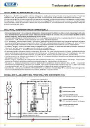
Connection of SAF<br />
The C.T.’s transformer are one of the most important part of the filtering system, because is from<br />
them that we can read the current to compensate. So this reading must be accurate and in order to<br />
read all the harmonic in the network, the quality should be high. And the secondary must be in<br />
according with the input stage of the regulator board of the filter.<br />
All these features combine to allow the component selection with Comar Condensatori S.p.A. after an<br />
accurate analysis of the plant.<br />
12 http://www.comarcond.com
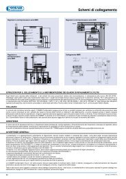
The SAF system<br />
The active filter has an extreme flexibility of connections in the existing plant and in the new ampliable<br />
installation. The possibility to insert a new filter in the installation with the easy connection of a couple of<br />
C.T.’s with the right dimension gives to the equipment great modularity speech.<br />
In every plant it’s easy to find a point for the connection of the current sensor (C.T.’s): for example inside a<br />
distribution panel or directly on the non linear load<br />
The filter has the possibility to be connected in parallel to increase the current to be compensated or in<br />
cascade to permit a new filter to be connected where an other filter is working before.<br />
So we can say that, SAF is the optimal solution to solve all the problems of filtering in harmonic current<br />
distortion.<br />
http://www.comarcond.com<br />
13
Power supply<br />
SAF features<br />
Supply Voltage 400 V ac (+10% -20%)<br />
Frequency 50 Hz / 60 Hz ± 1%<br />
Number of phase<br />
3 phase , 3 wire or 4 wire<br />
Type of load<br />
everything<br />
Standard C.T.’s<br />
Technical speech<br />
200 / 1A 1,5 kHz Cl. 0,5 not included<br />
Harmonic compensation<br />
Up to 50 order<br />
Response time<br />
< 1 ms<br />
Over load capability<br />
1,2 Irms<br />
Short circuit current<br />
120 kA, with fuse<br />
PFC<br />
Partial (selectable on board))<br />
Load with dynamic variation<br />
Yes<br />
Connection in parallel or cascade<br />
Yes<br />
Compatibility with passive filter<br />
Yes<br />
Net impedance<br />
Yes<br />
Limitation of the rated current<br />
Yes<br />
High modularity<br />
Yes<br />
Easy dimensioning<br />
Yes<br />
Auto tuning<br />
Yes<br />
THDi residual after filtering < 10%<br />
Class of protection IP 41<br />
Noise<br />
< 60 dB<br />
Ventilation<br />
forced<br />
Display<br />
Standard<br />
Option<br />
led<br />
LCD<br />
Operation condition<br />
Operating temperature 0 – 40 °C<br />
Operating altitude<br />
< 1000 m o.s.l.<br />
Relative humidity Up to 95%<br />
Electromagnetic compatibility<br />
Immunity<br />
Emission<br />
EN50081-2<br />
EN50082-2<br />
14 http://www.comarcond.com
Grafica Junior - Tel. 051.733020<br />
<strong>COMAR</strong> <strong>CONDENSATORI</strong> S.p.A.<br />
Headquarter:<br />
Via del Lavoro, 80 - CRESPELLANO (Bologna) ITALIA<br />
Export Department:<br />
P.O. Box 150 - 40011 ANZOLA EMILIA (Bologna) ITALY<br />
Tel. +39 051 733.383 - FAX +39 051 733.620<br />
Technical Department: project@comarcond.com<br />
Sales Department: export@comarcond.com<br />
http://www.comarcond.com<br />
I dati e le dimensioni possono essere modificati senza alcun preavviso.<br />
ED.02.62.ING REV.1 - Cod. 383026202