Chapter 2 - Svantek
Chapter 2 - Svantek
Chapter 2 - Svantek

Create successful ePaper yourself
Turn your PDF publications into a flip-book with our unique Google optimized e-Paper software.
SVAN 949 USER MANUAL .<br />
2 - 4<br />
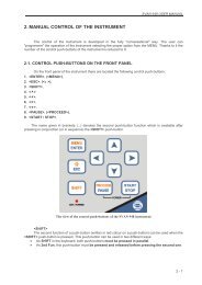
The view of the top cover of the SVAN 949 instrument in 1:1 scale<br />
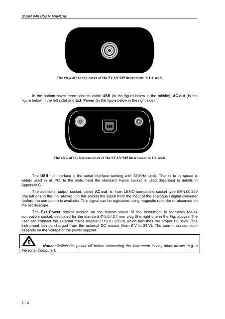
In the bottom cover three sockets exist: USB (in the figure below in the middle), AC out (in the<br />
figure below in the left side) and Ext. Power (in the figure below in the right side).<br />
The view of the bottom cover of the SVAN 949 instrument in 1:1 scale<br />
The USB 1.1 interface is the serial interface working with 12 MHz clock. Thanks to its speed is<br />
widely used in all PC. In the instrument the standard 4-pins socket is used described in details in<br />
Appendix C.<br />
The additional output socket, called AC out, is 1-pin LEMO compatible socket type ERN.00.250<br />
(the left one in the Fig. above). On this socket the signal from the input of the analogue / digital converter<br />
(before the correction) is available. This signal can be registered using magnetic recorder or observed on<br />
the oscilloscope.<br />
The Ext. Power socket located on the bottom cover of the instrument is Marushin MJ-14<br />
compatible socket, dedicated for the standard Φ 5.5 / 2.1 mm plug (the right one in the Fig. above). The<br />
user can connect the external mains adapter (110 V / 230 V) which furnishes the proper DC level. The<br />
instrument can be charged from the external DC source (from 6 V to 24 V). The current consumption<br />
depends on the voltage of the power supplier.<br />
Notice: Switch the power off before connecting the instrument to any other device (e.g. a<br />
Personal Computer).