2 MANUAL CONTROL OF THE INSTRUMENT 2.1 Control ... - Svantek
2 MANUAL CONTROL OF THE INSTRUMENT 2.1 Control ... - Svantek
2 MANUAL CONTROL OF THE INSTRUMENT 2.1 Control ... - Svantek

You also want an ePaper? Increase the reach of your titles
YUMPU automatically turns print PDFs into web optimized ePapers that Google loves.
2 <strong>MANUAL</strong> <strong>CONTROL</strong> <strong>OF</strong> <strong>THE</strong> <strong>INSTRUMENT</strong><br />
SVAN 958 USER <strong>MANUAL</strong><br />
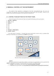
The control of the instrument is developed in the fully "conversational" way. The user can<br />
"programme" the operation of the instrument selecting the proper option from the MENU. Thanks to it,<br />
the number of the control push-buttons of the instrument is reduced to nine.<br />
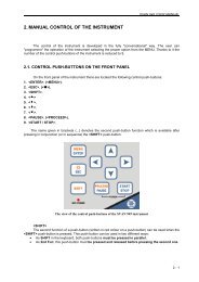
<strong>2.1</strong> <strong>Control</strong> push-buttons on the front panel<br />
On the front panel of the instrument, there are located the following control push-buttons:<br />
1. , (), []<br />
2. , (), []<br />
3. , [Markers]<br />
4. , [Markers]<br />
5. <br />
6. <br />
7. <br />
8. <br />
9. <br />
The name given in brackets (...) denotes the second push-button function which is available<br />
after pressing it in conjunction (or in sequence) with the push-button. The name given in square<br />
brackets […] denotes the push-button function which is available after pressing it in conjunction<br />
(or in a sequence) with the push-button.<br />
<br />
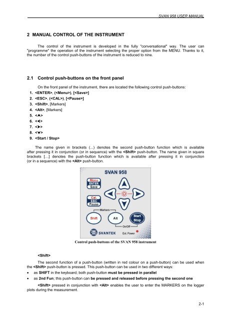
<strong>Control</strong> push-buttons of the SVAN 958 instrument<br />
The second function of a push-button (written in red colour on a push-button) can be used when<br />
the push-button is pressed. This push-button can be used in two different ways:<br />
• as SHIFT in the keyboard; both push-button must be pressed in parallel<br />
• as 2nd Fun; this push-button can be pressed and released before pressing the second one<br />
pressed in conjunction with enables the user to enter the MARKERS on the logger<br />
plots during the measurement.<br />
2-1
SVAN 958 USER <strong>MANUAL</strong> .<br />
Notice: The operation of this push button can be set as the “Shift” mode or the “2nd Fun.”<br />
mode in the SHIFT MODE (path: MENU / SETUP / KEYBOARD SETUP / SHIFT MODE), see Chapter<br />
with the SETUP list description.<br />
2-2<br />
<br />
This push-button enables one to choose the third push-button function in the case of [] and<br />
[] push-buttons. In order to select the third function user must press the and the second<br />
push-button simultaneously.<br />
<br />
This push-button enables one to start the measurement process, when the instrument is not<br />
measuring or to stop it, when the instrument is measuring. It is also possible to set such mode of this<br />
push-button, in which in order to start or stop the measurements the user has to press it simultaneously<br />
with the one.<br />
Notice: The changing of the push-button mode is performed<br />
in the START/STOP (path: MENU / SETUP / KEYBOARD SETUP / START/STOP), see Chapter<br />
with the SETUP list description.<br />
Notice: The simultaneous pressing of the and push-buttons switches<br />
the instrument on and off.<br />
<br />
This push-button enables one to enter the selected operation mode or to confirm control options.<br />
Some additional functions of this push-button will be described in the following chapters.<br />
()<br />
This push-button (pressed together with the one) enables the user to enter the main list<br />
containing six sub-lists: FUNCTION, INPUT, DISPLAY, FILE, SETUP and AUXILIARY FUNCTIONS.<br />
Each of the mentioned above sub-lists consists of the sub-lists, elements and data windows. These main<br />
sub-lists will be detailed described in the following chapters of the manual. Double pressed pushbutton<br />
enters the HISTORY list containing eight last opened sub-lists. It often speeds up the control of the<br />
instrument.<br />
[]<br />
This push-button (pressed together with the push-button) enables the user to save<br />
measurement results as a file in the internal instrument’s memory or on the USB memory stick. There are<br />
two ways of saving a file: with AUTO NAME option - saving a file with the name automatically increased<br />
by one (e.g. JAN0, JAN1, JAN2) or save a file by editing its name in the FILE NAME position (see Chapter<br />
with the FILE list description).
SVAN 958 USER <strong>MANUAL</strong><br />
This push-button closes the control lists, sub-lists or windows. It acts in opposite to the <br />
push-button. When the window is closed pressing the push-button, any changes made in it are<br />
(in almost all cases) ignored.<br />
[]<br />
This push-button enables one to break temporary the measurement process. The subsequent<br />
pressing of the push-button deletes the measurement result from the last one second.<br />
Up to fifteen last seconds of the measurement can be cancelled in this way.<br />
, <br />
These push-buttons enable one, in particular, to:<br />
• select the options in an active position in the "horizontal direction" (e.g. filter: LIN, A, C or G, Integration<br />
period: 1s, 2s, 3s, … etc.)<br />
• select the measurement result to be displayed (e.g. PEAK, MAX, MIN, etc.) in one-channel and multichannel<br />
modes of result’s presentation)<br />
• control the cursor in SPECTRUM, LOGGER and STATISTICS modes of result’s presentation<br />
• select the position of the character in the text edition (i.e. in the FILE NAME menu)<br />
• switch on/off markers 2 and 3<br />
• switch on/off the BACKLIGHT of the display ( + pressed together)<br />
(, )<br />
The , push-buttons pressed in conjunction (or in sequence) with the enable<br />
the user, in particular, to:<br />
• speed up the changing of the numerical values of the parameters (i.e. the step is increased from 1<br />
to 10 in the setting of START DELAY - path: MENU / INPUT / MEASUREMENT SETUP /<br />
START DELAY)<br />
• insert or delete a character in the text edition modes<br />
• change the statistics class (the number displayed after the letter L) in one-channel and multi-channel<br />
modes of result’s presentation<br />
Some other possible reactions of the instrument on the pressing of these push-buttons<br />
will be described in details in the following chapters.<br />
, <br />
The , push-buttons enable one, in particular, to:<br />
• change the mode of result’s presentation<br />
• select the proper character from the list in the text edition mode<br />
• switch the active sub-list in a list<br />
• programme the Real Time Clock (RTC) and TIMER<br />
• switch on/off markers 1 and 4<br />
Some other possible reactions of the instrument on the pressing of these push-buttons will be<br />
described in details in the following chapters.<br />
2-3
SVAN 958 USER <strong>MANUAL</strong> .<br />
2-4<br />
(, )<br />
The , push-buttons pressed in conjunction (or in sequence) with the enable one,<br />
in particular, to:<br />
• change the relation between the Y-axis and X-axis of all plots presented on the screen<br />
• switch the channels and profiles in one-channel and STATISTICS modes of result’s presentation<br />
• switch the active channel in multi-channels mode of result’s presentation<br />
Some other possible reactions of the instrument on the pressing of these push-buttons<br />
will be described in details in the following chapters.<br />
[Markers]<br />
The Markers enable the user to mark the special events, which occurred during the performed<br />
measurements (i.e. the airplane flight, the dog’s barking, the train’s drive etc.). In order to enter<br />
the markers the logger has to be switched on (path: MENU / INPUT / LOGGER SETUP /<br />
LOGGER MODE: ON) and one or more logger options (PEAK, MAX, MIN, RMS in the case of sound<br />
measurements and PEAK, P–P, MAX, RMS, VDV in the case of vibration measurements) in channels<br />
have to be chosen (path: MENU / INPUT / LOGGER SETUP / CHANNEL x). In order to enter the marker<br />
the user must press and push-buttons simultaneously during the measurement.<br />
The ENTER MARKER window opens and there are four available marker numbers. To choose marker<br />
number 1 the user must press push button (number 2 - , number - 3 and number 4 - ).<br />
The ENTER MARKER window closes automatically and chosen marker is activated (after pressing<br />
+ again active marker number will be highlighted). In order to switch off the marker,<br />
the user has to open the ENTER MARKER window and press this push-button, which refers to the marker<br />
to be switched off. Up to four markers can be switched on at the same time.<br />
The current state of the markers is indicated in the logger’s file and can be used to show them<br />
using dedicated presentation software.<br />
Display with the “MARKERS” (after pressing and together)<br />
Displays with the activated markers<br />
The exemplary presentation of the markers on the time-history plot is shown below (to view a plot<br />
with the markers the user has to transfer data to the proper software).
80<br />
70<br />
60<br />
50<br />
40<br />
30<br />
20<br />
13:30:00 13:30:09 13:30:17 13:30:26 13:30:35 13:30:43 13:30:52<br />
Time-history plot with the indication of the active markers<br />
SVAN 958 USER <strong>MANUAL</strong><br />
LEQ<br />
Marker 1<br />
Marker 2<br />
Marker 3<br />
Marker 4<br />
2-5
SVAN 958 USER <strong>MANUAL</strong> .<br />
2.2 Input and output sockets of the instrument<br />
The measurement inputs, called Channels, are placed on the top cover of the instrument.<br />
There are 4-pins Lemo compatible socket type ENB.0B.304 for Channels 1–3 and TNC for Channel 4,<br />
all with IEPE power supply for the accelerometers or microphone preamplifiers.<br />
The microphone preamplifier SV 12L has the proper plug-in with the screw for direct connection<br />
with the instrument to the TNC connector (Channel 4) but it is recommended to use the preamplifier<br />
with any of the extension cables (i.e. SC 26) or the SA 08 gooseneck. The same type of the connector<br />
should be used to attach one-channel accelerometer to Channel 4. The SC 27 coiled cable<br />
is recommended in this case. In order to connect the SV 12L microphone preamplifier to Channels 1–3<br />
one has to use the SC 49 cable (LEMO 4-pins plug to 3 * TNC sockets, 0.7 meters long). The SC 49<br />
or SC 39P (LEMO 4-pins plug to 3 * BNC sockets, 0.7 meters long) cables should be used to connect<br />
one-channel accelerometer to any of the Channels 1–3. The triaxial accelerometers can be easy<br />
connected to Channels 1–3 by means of the SC 38 cable (4-pins Microtech to LEMO 4-pins, 2.7 meters<br />
long). It is recommended to attach the SV 25 dosimeter microphone with the integrated preamplifier<br />
and a cable to Channel 4.<br />
Notice: Pay attention that the TNC connector should be always twisted to the light resistance<br />
but the LEMO connector is a push-pull only.<br />
2-6<br />
The full description of the signals connected to the sockets is given in the Appendix C.<br />
Top cover of the SVAN 958 instrument in 1:1 scale<br />
In the bottom cover there are four sockets, placed from the right to the left as follows: Ext. Pow.,<br />
USB Host, USB Device and I/O.<br />
Bottom cover of the SVAN 958 instrument in 1:1 scale<br />
The USB 1.1 Client interface (the USB Device socket) is the serial interface working with 12 MHz<br />
clock. Thanks to its speed, this interface is widely used in all PCs. In the instrument, the standard 4-pins<br />
socket is used described in details in Appendix C.<br />
The USB Host 1.1 interface can be used to connect the external storage, enabling the device<br />
to register virtually infinite sequence of measurement results.
SVAN 958 USER <strong>MANUAL</strong><br />
The Ext. Pow. socket located on the bottom cover of the instrument is Marushin MJ-14 compatible<br />
socket, dedicated for the standard Φ 5.5 / <strong>2.1</strong> mm plug (the right one in the Fig. above). The user can<br />
connect the external mains adapter (110 V / 230 V) which furnishes the proper DC level. The instrument<br />
can be charged from the external DC source (6 V / 500 mA DC ÷ 15 V / 250 mA DC). The current<br />
consumption depends on the voltage of the power supplier.<br />
The additional input / output socket, called I/O, is 1-pin LEMO compatible socket type ERN.00.250<br />
(the left one in the Fig. above). The function of this socket can be selected from menu (path: MENU /<br />
SETUP / EXT. I/O SETUP / MODE). The socket can be used as:<br />
• analogue output with the signal from the input of the analogue / digital converter (before<br />
the correction); this signal can be registered using magnetic recorder or observed on the oscilloscope<br />
(the ANALOG setting)<br />
• digital input for external interrupt (the DIGITAL IN setting)<br />
• digital output for external trigger (the DIGITAL OUT setting)<br />
Notice: Switch the power off before connecting the instrument to any other device<br />
(e.g. a printer or a Personal Computer).<br />
Front panel of the SVAN 958 instrument in 1:1 scale<br />
2-7
SVAN 958 USER <strong>MANUAL</strong> .<br />
2-8<br />
Rear panel of the SVAN 958 instrument in 1:1 scale