ST-360 POH - Tdmk.pmd - OU Aviation
ST-360 POH - Tdmk.pmd - OU Aviation
ST-360 POH - Tdmk.pmd - OU Aviation

Create successful ePaper yourself
Turn your PDF publications into a flip-book with our unique Google optimized e-Paper software.
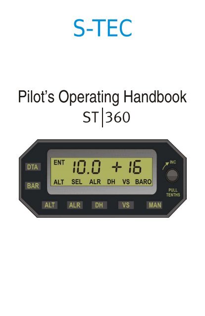
S-TEC<br />
Pilot’s Operating Handbook
S–TEC<br />
List of Effective Pages<br />
* Asterisk indicates pages changed, added, or deleted by<br />
current revision.<br />
Retain this record in front of handbook. Upon receipt of a<br />
Record of Revisions<br />
revision, insert changes and complete table below.<br />
Revision Number Revision Date Insertion Date/Initials<br />
1 st Ed. Oct 26, 00<br />
2 nd Ed. Jan 15, 08<br />
2nd Ed. Jan 15, 08<br />
i
Sec.<br />
Table of Contents<br />
S–TEC<br />
Pg.<br />
1 Overview...........................................................................................................1–1<br />
1.1 Document Organization....................................................................1–3<br />
1.2 Purpose..............................................................................................1–3<br />
1.3 General Control Theory....................................................................1–3<br />
1.4 Block Diagram....................................................................................1–4<br />
2 Pre-Flight Procedures...................................................................................2–1<br />
2.1 Pre-Flight Test....................................................................................2–3<br />
3 In-Flight Procedures......................................................................................3–1<br />
3.1 Selector / Alerter Operation..............................................................3–3<br />
3.1.1 Data Entry.............................................................................3–3<br />
3.1.2 Barometric (BARO) Calibration.......................................3–3<br />
3.1.3 Altitude (ALT) Select...........................................................3–4<br />
3.1.4 Vertical Speed (VS) Select.................................................3–5<br />
3.1.5 Decision Height (DH) Select............................................3–7<br />
3.1.6 Altitude Alerter (ALR) Function..........................................3–7<br />
3.1.7 Loss of Encoded Altitude..................................................3–8<br />
3.1.8 Selector / Alerter Disconnect............................................3–8<br />
3.2 Autopilot Operation............................................................................3–9<br />
4 Operating Parameters..................................................................................4–1<br />
4.1 Ranges.................................................................................................4–3<br />
5 Glossary...........................................................................................................5–1<br />
2nd Ed. Jan 15, 08<br />
iii
S–TEC<br />
Fig.<br />
List of Figures<br />
Pg.<br />
1–1 <strong>ST</strong>-<strong>360</strong> ALT / VS Selector / Alerter Block Diagram......................................1–5<br />
2–1 Selector / Alerter Display, All Segments and Annunciations Appear.......2–4<br />
2–2 Selector / Alerter Display, Enter Barometric Correction............................2–4<br />
3–1 Selector / Alerter Display, Loss of Encoded Altitude..................................3–8<br />
Table<br />
List of Tables<br />
Pg.<br />
2–1 Pre-Flight Test...............................................................................................2–3<br />
iv 2nd Ed. Jan 15, 08
S–TEC<br />
SECTION 1<br />
OVERVIEW<br />
2nd Ed. Jan 15, 08 1-1
1.1 Document Organization<br />
S–TEC<br />
Section 1 Overview<br />
Section 2 Pre-Flight Procedures<br />
Section 3 In-Flight Procedures<br />
Section 4 Operating Parameters<br />
Section 5 Glossary<br />
1.2 Purpose<br />
This Pilot's Operating Handbook (<strong>POH</strong>) provides Pre-Flight and In-Flight<br />
operating procedures for the S-TEC <strong>ST</strong>-<strong>360</strong> Altitude (ALT) / Vertical Speed (VS)<br />
Selector / Alerter.<br />
Note:<br />
This <strong>POH</strong> must be carried in the A/C and made available to the pilot at<br />
all times. It can only be used in conjunction with the Federal <strong>Aviation</strong><br />
Administration (FAA) approved Aircraft Flight Manual (AFM) or Aircraft Flight<br />
Manual Supplement (AFMS). Refer to the applicable AFM or AFMS for<br />
A/C specific information, such as unique ground tests, limitations, and<br />
emergency procedures.<br />
Note:<br />
The Selector / Alerter is a tool provided to aircraft owners, that serves to<br />
assist them with cockpit workload management. The ability of the<br />
Selector / Alerter to provide optimum assistance and performance is<br />
directly proportional to the pilot's knowledge of its operating procedures.<br />
Therefore, it is highly recommended that the pilot develop a thorough<br />
understanding of the Selector / Alerter and its operating procedures in<br />
Visual Meteorological Conditions (VMC), prior to using it under Instrument<br />
Flight Rules (IFR).<br />
1.3 General Control Theory<br />
The Selector / Alerter can be used with the following S-TEC autopilots:<br />
System Fifty Five X<br />
System Sixty Two<br />
System Sixty Five<br />
Pitch Stabilization System (PSS)<br />
2nd Ed. Jan 15, 08 1-3
S–TEC<br />
The Encoding Altimeter / Blind Encoder sends the encoded altitude to the<br />
Selector / Alerter. The encoded altitude must be converted to the true altitude,<br />
through barometric calibration.<br />
The selected altitude and selected vertical speed must be programmed into the<br />
Selector / Alerter. Thereafter, upon engaging the autopilot's vertical speed mode<br />
and arming its altitude hold mode, the aircraft will attain and hold the selected<br />
vertical speed. As the aircraft approaches the selected altitude, a scheduled<br />
reduction in the selected vertical speed will automatically occur. This enables<br />
the aircraft to transition from vertical flight to altitude capture, without adverse<br />
acceleration. Once the selected altitude has been captured, the autopilot's<br />
vertical speed mode will disengage and its altitude hold mode will engage. The<br />
aircraft will then hold the selected altitude.<br />
1.4 Block Diagram<br />
The Selector / Alerter Block Diagram is shown in Fig. 1-1.<br />
1-4 2nd Ed. Jan 15, 08
S–TEC<br />
Fig. 1-1. <strong>ST</strong>-<strong>360</strong> ALT / VS Selector / Alerter Block Diagram<br />
2nd Ed. Jan 15, 08 1-5
S–TEC<br />
SECTION 2<br />
PRE-FLIGHT PROCEDURES<br />
2nd Ed. Jan 15, 08 2-1
2.1 Pre-Flight Test<br />
S–TEC<br />
Prior to takeoff and with engine running, perform the actions shown in Table 2-1.<br />
For each action, verify the corresponding response where applicable.<br />
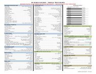
Table 2-1. Pre-Flight Test (continued on page 2-4)<br />
ACTION<br />
1. Set Battery Master Switch to ON<br />
position.<br />
RESPONSE<br />
------<br />
2. Set Avionics Master Switch to ON<br />
position.<br />
------<br />
3. Set Transponder Master Switch to<br />
ON position.<br />
------<br />
4. Set Encoding Altimeter / Blind<br />
Encoder Master Switch to ON<br />
position.<br />
------<br />
5. Set Autopilot Master Switch to ON<br />
position.<br />
------<br />
6. Complete Autopilot Pre-Flight<br />
Procedures contained in respective<br />
<strong>POH</strong>.<br />
------<br />
7. Set ALT Alerter Master Switch to<br />
ON position.<br />
A two-tone audible alert sounds once.<br />
All left numeric segments, all right<br />
polarity / numeric segments, and all<br />
annunciations (ENT, ALT, SEL, ALR,<br />
DH, VS, BARO) appear on Selector /<br />
Alerter display for 5 seconds, as<br />
shown in Fig. 2-1.<br />
Thereafter, only ENT annunciation<br />
and left numeral 29.9 (barometric<br />
pressure in inches mercury) appear,<br />
along with a flashing BARO<br />
annunciation, as shown in Fig. 2-2.<br />
2nd Ed. Jan 15, 08 2-3
S–TEC<br />
Fig. 2-1. Selector / Alerter Display, All Segments and Annunciations Appear<br />
Fig. 2-2. Selector / Alerter Display, Enter Barometric Correction<br />
2-4 2nd Ed. Jan 15, 08
S–TEC<br />
Table 2-1. Pre-Flight Test (continued from page 2-3)<br />
ACTION<br />
RESPONSE<br />
8. Set Altimeter to posted airport<br />
elevation.<br />
------<br />
9. Rotate Selector / Alerter Modifier<br />
Knob as required, until barometric<br />
pressure (inches of mercury) on<br />
display matches that shown on<br />
Kollsman scale of Altimeter.<br />
------<br />
Note:<br />
To convert barometric pressure to<br />
millibars, press Selector / Alerter BAR<br />
switch once.<br />
10. Press Selector / Alerter ALT<br />
switch.<br />
------<br />
11. Rotate Selector / Alerter Modifier<br />
Knob as required, until altitude on left<br />
numeric field of display is 400 feet<br />
above airport elevation.<br />
------<br />
12. Press Selector / Alerter VS<br />
switch.<br />
------<br />
13. Rotate Selector / Alerter Modifier<br />
Knob as required, until vertical speed<br />
polarity on right numeric field of<br />
display is positive (+).<br />
------<br />
14. Press Selector / Alerter ALT<br />
switch.<br />
------<br />
15. Set Heading Bug on DG or HSI<br />
under Lubber Line.<br />
------<br />
Note:<br />
This may not apply to the System<br />
Sixty PSS.<br />
2nd Ed. Jan 15, 08 2-5
S–TEC<br />
Table 2-1. Pre-Flight Test (continued from page 2-5)<br />
ACTION<br />
RESPONSE<br />
16. Press Autopilot HDG mode<br />
selector switch to engage heading<br />
mode.<br />
Note:<br />
This may not apply to the System<br />
Sixty PSS.<br />
HDG annunciation appears on<br />
Autopilot display.<br />
17. Press/Hold Autopilot VS mode<br />
selector switch, and then press ALT<br />
mode selector switch to engage<br />
vertical speed mode and arm altitude<br />
hold mode.<br />
ALT and VS annunciations appear on<br />
Autopilot display.<br />
18. Rotate Selector / Alerter Modifier<br />
Knob counter-clockwise (CCW) until<br />
Autopilot VS annunciation is<br />
extinguished.<br />
Selector / Alerter altitude on left<br />
numeric field of display is at airport<br />
elevation ± 100 feet.<br />
19. Disconnect Autopilot. ------<br />
20. Set Selector / Alerter for desired<br />
vertical speed and altitude hold<br />
following takeoff (reference section<br />
3.0).<br />
------<br />
2-6 2nd Ed. Jan 15, 08
S–TEC<br />
SECTION 3<br />
IN-FLIGHT PROCEDURES<br />
2nd Ed. Jan 15, 08 3-1
3.1 Selector / Alerter Operation<br />
S–TEC<br />
3.1.1 Data Entry<br />
Press the DTA switch, such that ENT is annunciated. Any of the following<br />
quantities can now be entered into the Selector / Alerter:<br />
Barometric Calibration (reference section 3.1.2)<br />
Selected Altitude (reference section 3.1.3)<br />
Selected Vertical Speed (reference section 3.1.4)<br />
Selected Decision Height (reference section 3.1.5)<br />
Whenever ENT is annunciated, the Selector / Alerter is decoupled from the<br />
autopilot. In that case, if the Selector / Alerter happens to have vertical speed<br />
command authority as indicated on its display, then the autopilot will hold the<br />
aircraft at the last selected vertical speed.<br />
Once the particular quantity has been entered, press the DTA switch again to<br />
make it operational. The ENT annunciation will extinguish as a result.<br />
Note:<br />
It is not necessary for ENT to be annunciated, in order to enter vertical speed<br />
selection changes.<br />
3.1.2 Barometric (BARO) Calibration<br />
The true altitude is the altitude above Mean Sea Level (MSL). The output of an<br />
Encoding Altimeter / Blind Encoder is the altitude expressed as a digital Gray<br />
Code, relative to the standard barometric pressure of 29.9 inches of mercury<br />
(inHg) or 1013 millibars (mb). This output is known as the encoded altitude.<br />
When the Altimeter is set to the true altitude, the barometric pressure at MSL will<br />
be shown on its Kollsman scale. The Selector / Alerter must then be calibrated<br />
to the Altimeter. This is accomplished by changing the barometric pressure<br />
setting on the Selector / Alerter to match the Kollsman scale. As a result, the<br />
encoded altitude at the input of the Selector / Alerter is internally converted to the<br />
true altitude, for use in making computations.<br />
Following the power-up self test (reference section 2.0), the barometric<br />
pressure setting is 29.9 inHg, and ready to be changed to match the Kollsman<br />
scale. Rotate the Modifier Knob clockwise (CW) to increase the barometric<br />
pressure setting, or counter-clockwise (CCW) to decrease the setting. Each<br />
detent changes the setting by 0.1 inHg, regardless of whether the Modifier Knob<br />
is pushed-in or pulled-out.<br />
The units of barometric pressure can be changed from inHg to mb, by pressing<br />
the BAR switch. Each CW or CCW detent of the Modifier Knob changes the<br />
barometric pressure setting by 1 mb, regardless of whether the Modifier Knob is<br />
pushed-in or pulled-out. When the setting is greater than 999 mb, the<br />
one-thousand digit is not shown. For example, a setting of 1013 mb would<br />
appear only as 013. The units of barometric pressure can be changed back to<br />
inHg, by pressing the BAR switch again.<br />
2nd Ed. Jan 15, 08 3-3
S–TEC<br />
Once the barometric pressure setting has been entered, press the DTA switch to<br />
make it operational, such that the ENT annunciation is extinguished and the<br />
BARO annunciation stops flashing.<br />
To change the barometric setting at times other than immediately following<br />
power-up, press the DTA switch such that ENT is annunciated. Then press the<br />
BAR switch, such that the BARO annunciation appears flashing. The setting can<br />
then be changed using the Modifier Knob as described above. Once the<br />
barometric pressure setting has been entered, press the DTA switch again to<br />
make it operational, such that the ENT annunciation is extinguished and the<br />
BARO annunciation stops flashing.<br />
The Selector / Alerter barometric pressure setting will automatically change to<br />
29.9 inHg or 1013 mb, above an altitude of 18,000 feet (FL 180). Even so, the<br />
last setting will continue to appear unchanged. Prior to descending below<br />
FL 180, change the barometric pressure setting as required for the new area.<br />
Once subsequently at or below FL 180, the Selector / Alerter will automatically<br />
reference this setting.<br />
3.1.3 Altitude (ALT) Select<br />
Press the DTA switch (more than once if necessary, depending on the current<br />
configuration of the Selector / Alerter), such that ENT and ALT are both annunciated,<br />
and the SEL annunciation is flashing. The selected altitude is now ready to be<br />
entered. Rotate the Modifier Knob clockwise (CW) to increase the altitude<br />
selection, or counter-clockwise (CCW) to decrease the selection. When the<br />
Modifier Knob is pushed-in, each detent changes the selection by 1000 FT.<br />
When the Modifier Knob is pulled-out, each detent changes the selection by<br />
100 FT.<br />
Once the selected altitude has been entered, press the DTA switch to make it<br />
operational, such that the ENT annunciation is extinguished and the SEL<br />
annunciation stops flashing.<br />
To display the true altitude, press the ALT switch. The SEL annunciation will<br />
extinguish as a result. To go back and display the selected altitude, press the<br />
ALT switch again. The SEL annunciation will re-appear as a result.<br />
If the newly selected vertical speed is not compatible with the selected altitude,<br />
then the latter will flash for 5 seconds to alert the pilot accordingly. There will be<br />
no automatic change to the selected altitude.<br />
Suppose that the aircraft is at an initial altitude of 5,000 FT, with a selected<br />
vertical speed of 100 FPM climbing and a selected altitude of 6,000 FT. If the<br />
selected vertical speed is subsequently changed to 100 FPM descending, then<br />
the selected altitude (6.0 on display) will flash for 5 seconds.<br />
Suppose that the aircraft is at an initial altitude of 6,000 FT, with a selected<br />
vertical speed of 100 FPM descending and a selected altitude of 5,000 FT. If the<br />
selected vertical speed is subsequently changed to 100 FPM climbing, then the<br />
selected altitude (5.0 on display) will flash for 5 seconds.<br />
3-4 2nd Ed. Jan 15, 08
3.1.4 Vertical Speed (VS) Select<br />
S–TEC<br />
Press the VS switch. The VS annunciation will appear, along with the selected<br />
vertical speed. The latter appears as a number in units of FPM x 100, prefixed by<br />
either a "+" to indicate a climb, or a "-" to indicate a descent (i.e., for example,<br />
+5 indicates 500 FPM climbing). For a climb, rotate the Modifier Knob clockwise<br />
(CW) to increase the vertical speed selection, or counter-clockwise (CCW) to<br />
decrease the selection. For a descent, rotate the Modifier Knob CCW to<br />
increase the vertical speed selection, or CW to decrease the selection.<br />
It is not necessary for ENT to be annunciated, in order to enter the selected<br />
vertical speed and for it to be operational. If ENT does happen to be annunciated,<br />
then the VS annunciation will flash when the VS switch is pressed. In that case,<br />
pressing the DTA switch will cause the ENT annunciation to extinguish, the VS<br />
annunciation to stop flashing, and the selected vertical speed to become<br />
operational.<br />
The Selector / Alerter now has vertical speed command authority. The ability to<br />
command vertical speed from the autopilot controls is disabled. These controls<br />
for each respective autopilot are as follows:<br />
System Fifty Five X - Modifier Knob<br />
System Sixty Two - UP Switch and DN Switch<br />
System Sixty Five - UP Switch and DN Switch<br />
Pitch Stabilization System (PSS) - UP Switch and DN Switch<br />
The acknowledgment that its commanded vertical speed is coming from the<br />
Selector / Alerter is as follows, for each respective autopilot:<br />
System Fifty Five X - SEL annunciation appears on optional Remote Annunciator<br />
- Current Vertical Speed extinguished (polarity and number)<br />
System Sixty Two - SEL annunciation appears on Programmer/Annunciator<br />
System Sixty Five - SEL annunciation appears on Annunciator<br />
Pitch Stabilization System (PSS) - No Acknowledgment<br />
To revert vertical speed command authority back to the autopilot controls, press<br />
the MAN switch. This will be acknowledged by the Selector / Alerter, through the<br />
extinguishment of its VS annunciation and selected vertical speed.<br />
During a climb or descent, a scheduled reduction in the selected vertical speed<br />
will automatically occur as the aircraft approaches the selected altitude. This<br />
enables the aircraft to transition from vertical flight to altitude capture, without<br />
adverse acceleration.<br />
The selected vertical speed will decrease in increments, as the aircraft arrives<br />
at fixed displacement points from the selected altitude. The result is that the<br />
vertical speed will be 300 FPM at altitude capture, which occurs 100 FT from the<br />
selected altitude.<br />
2nd Ed. Jan 15, 08 3-5
S–TEC<br />
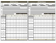
Suppose that the aircraft is at an initial altitude of 10,000 FT, with a selected<br />
vertical speed of 1600 FPM climbing and a selected altitude of 11,100 FT. The<br />
scheduled reduction in vertical speed will be as follows:<br />
Altitude (FT) Vertical Speed (FPM)<br />
10,000 1600<br />
10,100 1400<br />
10,200 1100<br />
10,300 1000<br />
10,400 900<br />
10,500 800<br />
10,600 700<br />
10,700 600<br />
10,800 500<br />
10,900 400<br />
11,000 300<br />
Suppose that the aircraft is at an initial altitude of 11,100 FT, with a selected<br />
vertical speed of 1600 FPM descending and a selected altitude of 10,000 FT.<br />
The scheduled reduction in vertical speed will be as follows:<br />
Altitude (FT) Vertical Speed (FPM)<br />
11,100 1600<br />
11,000 1400<br />
10,900 1100<br />
10,800 1000<br />
10,700 900<br />
10,600 800<br />
10,500 700<br />
10,400 600<br />
10,300 500<br />
10,200 400<br />
10,100 300<br />
However, there will be no scheduled reduction if the selected vertical speed is<br />
300 FPM or less.<br />
If the newly selected altitude requires a vertical speed polarity opposite to that<br />
previously selected, then the vertical speed selection will automatically change<br />
polarity and magnitude, the latter always being 500 FPM.<br />
Suppose that the aircraft is at an altitude of 5,000 FT, with a selected vertical<br />
speed of 1000 FPM climbing and a selected altitude of 10,000 FT. If the selected<br />
altitude is subsequently changed to 4,900 FT, then the vertical speed selection<br />
will automatically change to 500 FPM descending (-5 on display).<br />
Suppose that the aircraft is at an altitude of 10,000 FT, with a selected vertical<br />
speed of 1000 FPM descending and a selected altitude of 5,000 FT. If the<br />
selected altitude is subsequently changed to 10,100 FT, then the vertical speed<br />
selection will automatically change to 500 FPM climbing (+5 on display).<br />
3-6 2nd Ed. Jan 15, 08
3.1.5 Decision Height (DH) Select<br />
S–TEC<br />
This selection activates both an audible alert and a visual alert, first when<br />
entering and then when departing a 100 FT window about the actual decision<br />
height. The actual decision height does not have to be at the center of this<br />
window.<br />
Press the DTA switch, such that ENT is annunciated. Then press the DH switch.<br />
The DH annunciation will appear flashing. The selected decision height is now<br />
ready to be entered. Rotate the Modifier Knob clockwise (CW) to increase the<br />
decision height selection, or counter-clockwise (CCW) to decrease the<br />
selection. When the Modifier Knob is pushed-in, each detent changes the<br />
selection by 1000 FT. When the Modifier Knob is pulled-out, each detent<br />
changes the selection by 100 FT.<br />
Once the selected decision height has been entered, press the DTA switch to<br />
make it operational, such that the ENT annunciation is extinguished and the DH<br />
annunciation stops flashing. The selected decision height will extinguish after<br />
5 seconds, and be replaced by the true altitude (reference section 3.1.2). The<br />
selected decision height is now armed.<br />
Suppose that the aircraft is descending, and an alert about the actual decision<br />
height of 1160 FT is desired. Enter a selected decision height of 1200 FT (1.2 on<br />
display), which is the nearest 100 FT setting above the actual decision height,<br />
and make it operational. Once the aircraft arrives at 1250 FT, a two-tone audible<br />
alert will sound and the DH annunciation will flash for 3 seconds. This will occur<br />
again once the aircraft arrives at 1150 FT.<br />
Suppose that the aircraft is climbing, and an alert about the actual decision<br />
height of 1160 FT is desired. Enter a selected decision height of 1200 FT (1.2 on<br />
display), which is the nearest 100 FT setting above the actual decision height,<br />
and make it operational. Once the aircraft reaches 1150 FT, a two-tone audible<br />
alert will sound and the DH annunciation will flash for 3 seconds. This will occur<br />
again once the aircraft arrives at 1250 FT.<br />
To disarm the selected decision height, press the DH switch. The DH<br />
annunciation will extinguish as a result.<br />
3.1.6 Altitude Alerter (ALR) Function<br />
This function activates both an audible alert and a visual alert, at fixed<br />
displacement points from the selected altitude.<br />
Enter the selected altitude, and make it operational (reference section 3.1.3).<br />
Press the ALR switch to arm the altitude alerter function. The ALR annunciation<br />
will appear as a result. Thereafter, once the aircraft arrives at 1000 FT from the<br />
selected altitude, a two-tone audible alert will sound and the ALR annunciation<br />
will flash for 3 seconds. This will occur again, once the aircraft arrives at 300 FT<br />
from the selected altitude.<br />
Following capture of the selected altitude, should the aircraft ever happen to<br />
deviate from it by 300 FT, there will again occur the two-tone audible alert and<br />
flashing ALR annunciation.<br />
To disarm the altitude alerter function, press the ALR switch. The ALR<br />
annunciation will extinguish as a result.<br />
2nd Ed. Jan 15, 08 3-7
S–TEC<br />
3.1.7 Loss of Encoded Altitude<br />
Should the encoded altitude at the input of the Selector / Alerter ever be lost<br />
(i.e., interrupted), then a two-tone audible alert will sound 3 times, while the<br />
displayed altitude is replaced by flashing dashes as shown in Fig. 3-1.<br />
Thereafter, these dashes stop flashing but remain.<br />
In that event, the selected altitude is no longer attainable using the Selector /<br />
Alerter. In addition, if the Selector / Alerter happens to have vertical speed<br />
command authority as indicated on its display, then immediately press the MAN<br />
switch to revert such authority back to the autopilot.<br />
Should the encoded altitude be subsequently restored, then the dashes will be<br />
replaced by the displayed altitude. The Selector / Alerter can then be re-programmed<br />
for use.<br />
Fig. 3-1. Selector / Alerter Display, Loss of Encoded Altitude<br />
3.1.8 Selector / Alerter Disconnect<br />
If a Selector / Alerter malfunction is suspected, then set the ALT Alerter Master<br />
Switch to the OFF position. Do not attempt further use of the Selector / Alerter,<br />
until it has been inspected by authorized service personnel. A Selector / Alerter<br />
malfunction will not likely cause an autopilot failure.<br />
3-8 2nd Ed. Jan 15, 08
3.2 Autopilot Operation<br />
S–TEC<br />
Program the Selector / Alerter for the selected vertical speed and selected<br />
altitude. On the autopilot, press/hold the VS mode selector switch and then<br />
press the ALT mode selector switch, to engage the vertical speed mode and arm<br />
the altitude hold mode. The VS and ALT annunciations will appear on the<br />
autopilot display. The aircraft will attain and hold the selected vertical speed.<br />
As the aircraft approaches the selected altitude, a scheduled reduction in the<br />
selected vertical speed will automatically occur. This enables the aircraft to<br />
capture the selected altitude, without adverse acceleration. Once the selected<br />
altitude has been captured, the VS annunciation on the autopilot display will<br />
extinguish, to indicate engagement of the altitude hold mode. The aircraft will<br />
hold the selected altitude.<br />
Note:<br />
With the vertical speed mode engaged and the altitude hold mode armed:<br />
1. Pressing the ALT mode selector switch on the autopilot will engage the altitude<br />
hold mode, and disengage the vertical speed mode. Consequently, the VS<br />
annunciation will extinguish on the autopilot display. This may cause some<br />
adverse acceleration, as the autopilot works to hold the aircraft at the captured<br />
altitude.<br />
2. Pressing the VS mode selector switch on the autopilot will disarm the altitude<br />
hold mode, but leave the vertical speed mode engaged. Consequently, the ALT<br />
annunciation will extinguish on the autopilot.<br />
2nd Ed. Jan 15, 08 3-9
S–TEC<br />
SECTION 4<br />
OPERATING PARAMETERS<br />
2nd Ed. Jan 15, 08 4-1
4.1 Ranges<br />
S–TEC<br />
Altitude (ALT) Select Range<br />
0.0 to 35.9 Thousand FT<br />
Altitude Alerter (ALR) Function Range<br />
0.0 to 35.9 Thousand FT<br />
Barometric (BARO) Calibration Range<br />
27.9 to 32.0 inHg<br />
945 to 1083 mb<br />
Decision Height (DH) Select Range<br />
0.0 to 35.9 Thousand FT<br />
Vertical Speed (VS) Select Range<br />
Selector / Alerter PN 01279-PX: 1600 FPM Climbing or Descending<br />
Selector / Alerter PN 01279-PM: 3000 FPM Climbing or Descending<br />
2nd Ed. Jan 15, 08 4-3
S–TEC<br />
SECTION 5<br />
GLOSSARY<br />
2nd Ed. Jan 15, 08 5-1
Term<br />
A/C<br />
AFM<br />
AFMS<br />
ALR<br />
ALT<br />
BAR<br />
BARO<br />
CCW<br />
CW<br />
DG<br />
DH<br />
DN<br />
DTA<br />
ENT<br />
FAA<br />
FL<br />
FPM<br />
FT<br />
HDG<br />
HSI<br />
IFR<br />
INC<br />
inHg<br />
MAN<br />
mb<br />
MSL<br />
PN<br />
<strong>POH</strong><br />
PSS<br />
SEL<br />
VMC<br />
VS<br />
Meaning<br />
Aircraft<br />
Aircraft Flight Manual<br />
Aircraft Flight Manual Supplement<br />
Alerter<br />
Altitude<br />
Barometric<br />
Barometric<br />
Counter-Clockwise<br />
Clockwise<br />
Directional Gyro<br />
Decision Height<br />
Down<br />
Data<br />
Enter<br />
Federal <strong>Aviation</strong> Administration<br />
Flight Level<br />
Feet–per–Minute<br />
Feet<br />
Heading<br />
Horizontal Situation Indicator<br />
Instrument Flight Rules<br />
Increment<br />
Inches of Mercury<br />
Manual<br />
Millibars<br />
Mean Sea Level<br />
Part Number<br />
Pilot's Operating Handbook<br />
Pitch Stabilization System<br />
Select<br />
Visual Meteorological Conditions<br />
Vertical Speed<br />
S–TEC<br />
2nd Ed. Jan 15, 08 5-3
Information contained in this document is subject to change<br />
without notice. © 2008 S-TEC. All rights reserved. Printed in<br />
the United States of America. S-TEC and the S-TEC logo<br />
are registered trademarks of S-TEC.<br />
Notice:<br />
Contact S-TEC Customer Support at 800-872-7832 for a<br />
Return Material Authorization (RMA) number prior to the return of<br />
any component for any reason.<br />
One S–TEC Way<br />
Municipal Airport<br />
Mineral Wells, TX 76067–9236<br />
Tel: 800–872–7832<br />
Fax: 940–325–3904<br />
www.s-tec.com<br />
www.cobham.com<br />
S–TEC PN 87110