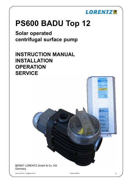
PS600 BADU Top 12 - Dr Solar
PS600 BADU Top 12 - Dr Solar
PS600 BADU Top 12 - Dr Solar

You also want an ePaper? Increase the reach of your titles
YUMPU automatically turns print PDFs into web optimized ePapers that Google loves.
<strong>PS600</strong> <strong>BADU</strong> <strong>Top</strong> <strong>12</strong><br />
<strong>Solar</strong> operated<br />
centrifugal surface pump<br />
INSTRUCTION MANUAL<br />
INSTALLATION<br />
OPERATION<br />
SERVICE<br />
BERNT LORENTZ GmbH & Co. KG<br />
Germany<br />
www.lorentz.de / info@lorentz.de release 050509<br />
1
Manual <strong>PS600</strong> <strong>BADU</strong> <strong>Top</strong> <strong>12</strong><br />
Contents<br />
1 SYSTEM REPORT FORM .................................................................................................................................. 5<br />
2 ELECTRICAL INSTALLATION ........................................................................................................................... 4<br />
2.1 Pump Controller <strong>PS600</strong> .................................................................................................................................. 4<br />
2.2 Mechanical Installation .................................................................................................................................... 4<br />
2.3 Controller Input Wiring .................................................................................................................................... 4<br />
2.4 Electrical Installation - Terminals ..................................................................................................................... 5<br />
2.5 Battery-Based System .................................................................................................................................... 5<br />
2.6 Wire Sizing ...................................................................................................................................................... 5<br />
3 OPERATING THE PUMP .................................................................................................................................... 6<br />
4 AUTOMATIC CONTROLL FOR FULL TANK SHUT OFF .................................................................................. 8<br />
5 TROUBLE SHOOTING ....................................................................................................................................... 9<br />
6 MAINTENACE ................................................................................................................................................... 10<br />
7 Warranty ............................................................................................................................................................ 10<br />
8 SYSTEM WIRING DIAGRAM ........................................................................................................................... 11<br />
WARNING<br />
disregard might lead to injury or<br />
damage the installation<br />
CAUTION<br />
recommended to avoid disfunction<br />
or premature ageing of the<br />
pump etc.<br />
ADVICE<br />
www.lorentz.de / info@lorentz.de release 050509<br />
2
Manual <strong>PS600</strong> <strong>BADU</strong> <strong>Top</strong> <strong>12</strong><br />
2 SYSTEM REPORT FORM<br />
System and Components<br />
System Voltage<br />
V<br />
Date of Purchase<br />
Purchased from<br />
Battery System yes no<br />
if not:<br />
Quantity of <strong>Solar</strong> Modules (panels)<br />
<strong>Solar</strong> Module Brand<br />
Module Model #<br />
Controller Model<br />
<strong>PS600</strong><br />
Controller Serial #<br />
Thank you for purchasing a LORENTZ PUMP.<br />
Before you begin Check the model numbers of<br />
all the components of your system, and verify<br />
that they are the items that you ordered. Also<br />
check against the PUMP specifications and<br />
performance charts (end of this manual) to be<br />
sure the system is appropriate for your application.<br />
Please fill in the SYSTEM REPORT. This will<br />
be essential information if any problems occur.<br />
Read the manuals of pump end, charger<br />
(optionally) and other components used in your<br />
system<br />
3
Manual <strong>PS600</strong> <strong>BADU</strong> <strong>Top</strong> <strong>12</strong><br />
2.1 Pump Controller <strong>PS600</strong><br />
> Controlling and monitoring of the motor<br />
> Integrated MPP-Tracking<br />
> LVD protection (low voltage disconnect) for 48V<br />
batteries<br />
> Check and display the operating states<br />
> Two control inputs for float- or pressure switches,<br />
remote control, etc.<br />
> 92% max. efficiency (motor + controller)<br />
> Adjustable maximum RPM setting<br />
PV max. open circuit (Voc)<br />
(4-6 pc of <strong>12</strong>V nominal solar panels)<br />
150 V DC<br />
Input voltage battery:<br />
48V DC<br />
Input current / Power, max.<br />
unlimited,<br />
(Controller regulates max Power)<br />
Battery low voltage disconnect:<br />
44 V DC<br />
Restart voltage: 48 V DC<br />
Output:<br />
13-45V EC PWM 3-phase<br />
Type of enclosure: IP 54<br />
Ambient temperature: -20 °C to +50 °C<br />
Weight:<br />
4.8 kg<br />
Dimensions:<br />
425 x 175 x 150 mm<br />
2. 2 Mechanical Installation<br />
2.3 Controller Input Wiring<br />
Position If it is outdoors, mount the controller in a<br />
vertical position to assure that rain will not enter the<br />
box.<br />
Battery system Place the controller near the<br />
batteries but safely isolated from the battery terminals<br />
and from corrosive gases. (Batteries must be in<br />
a cool location for best longevity and enclosed for<br />
cleanliness and safety.) Connect the battery directly<br />
with the + and – Terminal of the controller. Do not<br />
use the load terminals of the charge controller as<br />
they maybe not strong enough to allow the start<br />
current to flow. The <strong>PS600</strong> Controller has a low<br />
voltage function to protect the batteries from deep<br />
discharge. The charger ( additional) is only needed<br />
for charging the batteries.<br />
WARNING TEST THE VOLTAGE before<br />
connecting power to the controller.<br />
Voltage (open circuit) must not exceed<br />
150V for <strong>PS600</strong> Controller. (Even in cloudy<br />
weather, the open circuit voltage will be<br />
near maximum.)<br />
WARNING Do not apply a direct connection<br />
or an amp meter between + and –<br />
when the controller is connected. A short<br />
circuit here will cause a strong discharge.<br />
WARNING SOLAR-DIRECT systems only —<br />
Do not connect any electrical load to the<br />
solar array if it is not part of the LORENTZ<br />
Pump system. Connection of a battery<br />
charger, active solar tracker controller, electric<br />
fence charger, or other load simultaneously<br />
with LORENTZ PS systems may “confuse”<br />
the controller and prevent proper operation.<br />
www.lorentz.de / info@lorentz.de release 050509<br />
4
Manual <strong>PS600</strong> <strong>BADU</strong> <strong>Top</strong> <strong>12</strong><br />
2.4 Electrical Installation-Terminals<br />
Power IN For PV-direct systems, a two-pole disconnect<br />
switch may be installed between the solar array<br />
and the controller. Switch it off to prevent shock and arc<br />
burn hazard during installation and maintenance, or if<br />
the system will be shut down for the season. For Battery<br />
systems: Connect the controller directly to the plus and<br />
minus terminals of the Battery. Do not connect to the<br />
load terminals of the charger as they may be not strong<br />
enough to provide the starting current. A 20 Amp slow<br />
blow fuse must be installed between. The controller and<br />
the battery.<br />
Ground Connect the ground wire to the ground<br />
connection in the controller. Grounding helps to prevent<br />
shock hazard if there is a fault in the motor.<br />
L1 – L2 – L3 ECDRIVE ® requires four-conductor (fourwire)<br />
cable between the controller and the motor. The<br />
three wires L1, L2 and L3 carry power. The fourth wire<br />
carries ground. To reverse direction of rotation reverse<br />
any two wires.<br />
No. 1 and 2 In order to protect the pump from being<br />
damaged by dry running connect one well probe cable<br />
to each terminal. If dry run protection is not needed,<br />
short cut these two terminals.<br />
No. 3, 4 and 5 Connect any kind of external switch<br />
(NO or NC type) for remote control of the controller. In<br />
case no switch is used the terminals No. 4 and 5 have<br />
to be connected with a short cable (factory setting). In<br />
case a NO-switch is used (connected to the terminals<br />
No. 3 and 4) the short cable (connecting the terminals<br />
No. 4 and 5) must remain installed.<br />
No. 6 and 7 Connect these two terminals to switch the<br />
controller to battery mode. The motor will be switched<br />
OFF by the controller if the input voltage is below 11 V<br />
for a <strong>12</strong> V battery system and 22 V for a 24V battery<br />
system in order to protect the battery. If the battery<br />
voltage increases to 13 or 26 V the motor will be<br />
switched ON automatically.<br />
Terminals inside the PS-XXX controller.<br />
“Max. RPM setting” is at right. To reduce RPM<br />
turn counter-clockwise<br />
2.5 Battery-Based Systems<br />
2.6 Wire Sizing<br />
<strong>PS600</strong> pump systems can be operated from batteries.<br />
Short Circuit protection Install a fuse or circuit breaker<br />
near the power source. For either 48V , use a 20 amp<br />
circuit breaker or a time-delay (slow blow) fuse. The<br />
purpose of this protection is for safety in case of a wiring<br />
fault, and to provide a means of disconnect when installing<br />
or maintaining the system. <strong>PS600</strong> controllers have<br />
electronic over-current protection against motor overload.<br />
Low-voltage disconnect function. Lead-acid batteries<br />
can be permanently damaged by over-discharge when<br />
the voltage falls below a critical point. To prevent this, the<br />
PS battery-system controller will turn off at low voltage,<br />
and turn back on only after the battery has recovered<br />
significantly. The set points are:<br />
48V SYSTEM: OFF at 44V ON at 48V<br />
A controller in disconnect mode can be reset manually by<br />
turning off/on, but it will quickly disconnect again if the<br />
battery is not gaining a substantial recharge.<br />
Wire Sizing for the DC circuit Wire must be sized for<br />
no more than 5% voltage drop at 20 amps (starting).<br />
Refer to a wire sizing chart for 48V, or follow these<br />
examples:<br />
<strong>Solar</strong> Direct Systems<br />
#10 wire to maximum distance of 30 ft.<br />
Metric: 4 sq. mm to max. 20m<br />
Battery Systems:<br />
#10 wire to maximum distance of 30 ft.<br />
Metric: 4 sq. mm to max. 15m<br />
GREATER LENGTHS For each 150% increase, use<br />
next larger wire size<br />
5
Manual <strong>PS600</strong> <strong>BADU</strong> <strong>Top</strong> <strong>12</strong><br />
3 OPERATING THE PUMP<br />
This explains the function of the switch and<br />
the indicator lights on the pump controller.<br />
SWITCH<br />
POWER ON/OFF<br />
When switched off/on during operation, it resets all<br />
system logic.<br />
Indicator lights<br />
SYSTEM (green)<br />
The controller is switched on and the power source<br />
is present. In low-power conditions, the light may<br />
show even if there is not enough power to run the<br />
pump.<br />
PUMP ON (green)<br />
Motor is turning. Sequence of flashing indicates<br />
pump speed. See below sequence<br />
PUMP OVERLOAD (green changes to red)<br />
SOURCE LOW (red)<br />
The water source dropped below the level of the lowwater<br />
probe. After the water level recovers, the pump<br />
will restart, but this light will slowly flash until the sun<br />
goes down, power is interrupted, or the POWER<br />
switch is reset. This indicates that the water source<br />
ran low at least once since the previous off/on cycle.<br />
TANK FULL (red)<br />
Pump is turned off by action of the remote float<br />
switch (or pressure switch or manual switch,<br />
whichever is wired to the “remote float switch”<br />
terminals.<br />
BATTERY LOW (tank light flashes)<br />
Battery systems only – battery voltage fell to 44V,<br />
and has not yet recovered to 48V.<br />
RPM indication: Pump speed can be read off by<br />
the flashing sequence of the Pump ON LED.<br />
LED ON > 900<br />
One flash > <strong>12</strong>00<br />
Two flash > 1600<br />
Three flash > 2000<br />
Four flash > 2400<br />
Five flash > 2800<br />
6
Manual <strong>PS600</strong> <strong>BADU</strong> <strong>Top</strong> <strong>12</strong><br />
Operating the Pump continued<br />
Starting the pump Be sure there is not a<br />
closed valve or other obstruction in the water<br />
line.<br />
Fill the pump with clean water until the water<br />
level reaches the inlet connection. Coat the<br />
O-Ring seal with Vaseline, close the lid by<br />
hand and make sure that it is well in the<br />
housing groove. Otherwise the pump will<br />
prime insufficiently or not at all.<br />
NEVER LET THE PUMP RUN DRY, NOT<br />
EVEN FOR THE PURPOSE OF CHECKING<br />
THE DIRECTION OF ROTATION !<br />
Switch on the array disconnect switch, and<br />
toggle the power switch on the controller. It is<br />
normal to leave the switches on at all times,<br />
unless you desire to have the system off.<br />
A solar-direct pump should start under the<br />
following conditions<br />
1. clear sunshine at an angle of about 20° or<br />
more from the surface of the solar array<br />
2. cloudy conditions, if the sunshine is bright<br />
enough to cast some shadow<br />
3. low-water probe submersed in the water<br />
source (or bypassed in the controller) –<br />
Water-Low light OFF<br />
4. full-tank float switch is not responding to a<br />
full tank – Tank-Full light OFF<br />
5. battery system only – voltage is higher<br />
than the low-voltage disconnect point of<br />
44V.<br />
When sunshine is insufficient When<br />
sunshine on the array is present, but too<br />
weak for the pump to run, it will attempt to<br />
start about every <strong>12</strong>0 seconds. During each<br />
attempt, you will see the PUMP ON light<br />
come on.<br />
When pump runs slowly (PUMP ON) under<br />
weak sun conditions the pump may spin<br />
without lifting water all the way to the outlet.<br />
This is normal.<br />
When pump stops from a sudden shadow on<br />
the solar array<br />
If a shadow suddenly passes over the array,<br />
like if you walk in front if it, the controller will<br />
lose track of the input voltage. This does<br />
NOT indicate a problem. The pump will<br />
attempt to restart after the normal delay.<br />
Time delays<br />
1. After pump stops due to insufficient<br />
sunshine – <strong>12</strong>0 SECONDS<br />
2. After full-tank float switch resets – 2 to 3<br />
SECONDS<br />
3. After low-water probe regains contact with<br />
water in the source -– 20 MINUTES but<br />
the indicator light will slowly falsh for the<br />
rest of the solar day, or until power is<br />
disrupted or the controller is turned off/on.<br />
4. Battery systems – after low voltage<br />
disconnect point is reached, delay to stop<br />
pump – a few SECONDS. After voltage<br />
recovers, delay to re-connect – a few<br />
SECONDS<br />
To force a quick start To test or observe the<br />
system, you can bypass the normal time<br />
delays. Switch the POWER switch off then on<br />
again. The pump should start immediately if<br />
sufficient power is present.<br />
7
Manual <strong>PS600</strong> <strong>BADU</strong> <strong>Top</strong> <strong>12</strong><br />
4 Automatic Control For Full-Tank Shutoff<br />
We recommend the use of a float switch or<br />
other means to prevent overflow of your tank.<br />
This will stop the pump when the tank is full,<br />
then reset when the level drops. This conserves<br />
ground water, prevents overflow, and<br />
eliminates unnecessary pump wear. PS-XXX<br />
controllers allow the use of small signal cable<br />
to a remote float switch, even if the tank is a<br />
long distance away.<br />
Float switch requirements<br />
1. A switch must be used, not wet electrodes.<br />
2. The preferred system requires a float<br />
switch to MAKE contact on rise to turn the<br />
pump OFF. This is called “normally open”<br />
(N.O.). It may be commercially labeled as a<br />
“pump down” switch, but here it works in<br />
reverse, to allow pumping up.<br />
Float switch cable requirements<br />
1. Two wires are needed.<br />
2. Minimum wire size #18<br />
AWG ( 1mm²). This is good<br />
for a distance as far as 2000<br />
feet (600 m).<br />
3. The cable must be suitable<br />
for its environment.<br />
cable<br />
weight<br />
sealed<br />
cable clamp<br />
4. If it must run a long<br />
distance, use twisted-pair<br />
shielded cable to reduce the<br />
chance of damage from lightning-induced<br />
surge.<br />
Grounding shielded float switch cable If<br />
you use shielded cable, connect the shield to<br />
ground AT THE CONTROLLER ONLY. DO<br />
NOT ground the shield at the float switch.<br />
This will reduce surges induced by nearby<br />
lightning.<br />
pump off<br />
pump on<br />
pumping<br />
range<br />
Wiring to the controller<br />
The controller offers two<br />
options for connection of a<br />
remote switch. These allow<br />
the use of either a<br />
“normally open” (N.O.) or<br />
a “normally closed” (N.C.)<br />
switch. “Normal” refers to<br />
the status of the contacts<br />
when the switch is DOWN<br />
and calling for water.<br />
Wiring a “normally open switch” Connect the switch to terminals 3 and 4 (NO and<br />
common) and connect terminals 4 and 5 together, as illustrated.<br />
Closing (connecting) the switch circuit turns the pump OFF<br />
Wiring a “normally closed/reverse action switch” Connect the switch to termins 4<br />
and 5. Closing (connecting) the switch turns the pump ON<br />
8
Manual <strong>PS600</strong> <strong>BADU</strong> <strong>Top</strong> <strong>12</strong><br />
5 TROUBLE SHOOTING<br />
Please read this section before calling for help.<br />
If you call for help, please refer to the model and serial<br />
numbers. (See SYSTEM REPORT, page 3.)<br />
If The Pump Does Not Run<br />
Most problems are caused by wrong connections (in a<br />
new installation) or failed connections, especially<br />
where a wire is not secure and falls out of a terminal.<br />
The System ON light will indicate that system is<br />
switched on and connected to the controller. It<br />
indicates that VOLTAGE is present but (in a solardirect<br />
system) there may not be sufficient power to<br />
start the pump. It should attempt to start at intervals of<br />
<strong>12</strong>0 seconds.<br />
Pump attempts to start every <strong>12</strong>0 seconds but<br />
doesn’t run<br />
The controller makes a slight noise as it tries to start<br />
the pump. The pump will start to turn or just vibrate a<br />
little.<br />
1. There may be insufficient power reaching the<br />
controller. A solar-direct (non-battery) system<br />
should start if there is enough sun to cast a slight<br />
shadow. A battery system should start if the supply<br />
voltage is greater than 44V.<br />
2. If the pump was recently connected (or reconnected)<br />
to the controller, it may be running in<br />
reverse direction due to wiring error.<br />
3. If the motor shaft only vibrates and will not turn, it<br />
may be getting power on only two of the three<br />
motor wires. This will happen if there is a broken<br />
connection or if you accidentally exchanged one of<br />
the power wires with the ground wire.<br />
4. The pump or pipe may be packed with mud, clay,<br />
sand or debris.<br />
PUMP OVERLOAD (PUMP ON light shows red<br />
instead of green) The system has shut off due to an<br />
overload. This can happen if the motor or pump is<br />
blocked or very difficult to turn and is drawing excessive<br />
current (hard to turn). Overload detection requires<br />
at least 250 Watt output of the solar array. This can be<br />
caused by a high concentration of solids in the<br />
pump.The controller will make 3 start attempts before<br />
shutting down the system. The System ON LED will be<br />
OFF and the red OVERLOAD LED ON. The system<br />
will not reset until the ON / OFF switch is turned OFF<br />
and ON again. See Troubleshooting, Section 9.3<br />
“HIGHER CURRENT”.<br />
Inspect the solar array<br />
1. Is it facing the sun<br />
2. Is there a partial shadow on the array If only 10%<br />
of the array is shadowed, it can stop the pump!<br />
Inspect all wires and connections<br />
1. Look carefully for improper wiring (especially in a new<br />
installation).<br />
2. Make a visual inspection of the condition of the wires and<br />
connections. Wires are often chewed by animals if they are<br />
not enclosed in conduit (pipe).<br />
3. Pull wires with your hands to check for failed connections.<br />
Inspect the controller<br />
1. Remove the screws from the bottom plate of the controller.<br />
Move the plate downward (or the controller upward) to reveal<br />
the terminal block where the wires connect.<br />
2. First, check for a burnt smell. This will indicate a failure of the<br />
electronics. Look for burnt wires, bits of black debris, and any<br />
other signs of lightning damage.<br />
3. Inspect the grounding wires and connections! Most controller<br />
failures are caused by an induced surge from nearby lightning<br />
where the system is NOT effectively grounded. Ground<br />
connections must be properly made and free of corrosion.<br />
Check the low-water probe system<br />
If the controller indicates “SOURCE LOW” when the pump is in<br />
the water, inspect the low-water probe system. The probe is<br />
mounted on, or near the pump. If inspection is not feasible, you<br />
can bypass the probe or test it electrically.<br />
Check the full-tank float switch<br />
If the controller indicates “TANK FULL” when the storage tank is<br />
not full, inspect the float switch system. If your system has a float<br />
switch, it will be mounted in the tank. If inspection is not feasible,<br />
you can bypass the switch or test it electrically.<br />
Force a quick start<br />
If you restore a connection or bypass the probe or float switch,<br />
there is no need to wait for the normal time delay. Switch the on/<br />
off switch (or the power source) off then on again. The pump<br />
should start immediately if sufficient power is present.<br />
If the pump responds to the bypass tests above but not to the<br />
float switch, the wires may be shorted (touching each other) or<br />
open (broken), or the switch may be stuck with debris, or out of its<br />
correct position.<br />
1. Is the solar array receiving shadow-free light (It only takes a<br />
small shadow to stop it.) Is it oriented properly toward the<br />
south, and tilted at the proper angle<br />
2. Be sure you have the right pump for the total lift that is<br />
required.<br />
3. Be sure all wire and pipe runs are sized adequately for the<br />
distance. Refer to wire sizing in the pump sizing table.<br />
4. Inspect and test the solar array circuit and the controller<br />
output, as above. Write down your measurements.<br />
5. There may be a leak in the pipe from the pump.<br />
6. There is a “max. RPM” adjustment in the controller. It may<br />
have been set to reduce the flow as low as 30%.<br />
9
Manual <strong>PS600</strong> <strong>BADU</strong> <strong>Top</strong> <strong>12</strong><br />
6 MAINTENANCE<br />
Controller and Pump<br />
The controllers electronic has no moving or<br />
wearing parts. It requires no maintenance.<br />
There are rubber plugs to seal at the bottom,<br />
unused conduit holes. Inspect them to insure<br />
that the controller is sealed from moisture,<br />
insects, etc. Check that mounting and conduit<br />
hardware is tight.<br />
Motor The motor requires no maintenance.<br />
It has no brushes or other frequently wearing<br />
parts.<br />
Pump end The pump mechanism (pump<br />
end) is lubricated only by water and requires<br />
no maintenance. It may wear after some<br />
years, especially if there are abrasive solids in<br />
the water. If sand accumulates in the storage<br />
tank or pipes as a result of normal pumping, it<br />
is best to take periodic measurement of the<br />
pump’s performance. A worn pump end can<br />
be replaced in the field.<br />
7 WARRANTY<br />
<strong>BADU</strong> <strong>Top</strong> pump and PS-xxx controllers<br />
are warranted by the manufacturer to be<br />
free from defects in material and workmanship<br />
for two (2) years from date of purchase.<br />
Failure to provide correct installation, operation,<br />
or care for the product, in accordance<br />
with the instruction manual, will void the<br />
warranty. Product liability, except where<br />
mandated by law, is limited to repair or<br />
replacement, at the discretion of the manufacturer<br />
or importer.<br />
Neither manufacturer nor importer is responsible<br />
for the labor or other charges necessitated<br />
by the removal, transportation, or<br />
reinstallation of any defective product.<br />
Warranty does not cover damage due to<br />
failure to install the device properly, mishandling<br />
or abuse, failure to protect circuitry from<br />
weather exposure, failure to protect from<br />
overheating due to sun exposure or other<br />
sources of heat, failure to protect from salt<br />
spray or other corrosive factors, failure to seal<br />
out insects, spiders or rodents, lightning, flood<br />
or other acts of nature, or failure of or inappropriate<br />
application of peripheral devices<br />
including lightning or surge protectors.<br />
<strong>BADU</strong> <strong>Top</strong> pumps are designed for pumping<br />
thin, clean, non-aggressive, non explosive<br />
liquids not containing solid or long firbred<br />
particles larger then sand grains<br />
Warranty does not cover damage due to sand<br />
or abrasive particles in the water, or incompatibility<br />
of pump materials with corrosive<br />
substances or hydrocarbon or petroleum<br />
impurities, or from running the pump with an<br />
insufficient supply of water.<br />
No specific claim of merchantability shall be<br />
assumed or implied beyond what is printed on<br />
the manufacturer’s or importer’s printed<br />
literature. No liability shall exist from circumstances<br />
arising from the inability to use the<br />
product, or its inappropriateness for any<br />
specific purpose. It is the user’s responsibility<br />
to determine the suitability of the product for<br />
any particular use.<br />
In all cases, it shall be the responsibility of the<br />
customer to ensure a safe installation in<br />
compliance with local, state and national<br />
electrical codes.<br />
10
Manual <strong>PS600</strong> <strong>BADU</strong> <strong>Top</strong> <strong>12</strong><br />
8 System Wiring Diagram for <strong>Solar</strong>-direct (non-battery) System<br />
This is an example, using 4 X <strong>12</strong>V-nominal PV modules. Your system may vary in the number,<br />
voltage, and configuration of PV modules. If the diagram for YOUR system is not attached<br />
here, ask your pump supplier. The system here below is typical for a <strong>PS600</strong> system ( 4 to 6<br />
modules in Series)<br />
PV Modules (<strong>Solar</strong> Panels)<br />
Before connecting the array to the<br />
controller measure the opencircuit<br />
voltage. It must be within a<br />
range of<br />
<strong>PS600</strong> : 75-135V DC<br />
Float Switch (optional)<br />
Float Switch Kit makes contact on<br />
rise to stop pump.<br />
Connect termins 3 (NO) and 4<br />
(COM) and connect terminals 4<br />
and 5 with jumper wire.<br />
For wire size, refer<br />
to Pump Sizing<br />
Table<br />
+ - <strong>12</strong><br />
Power In<br />
low-water sensor probe<br />
connect to bypass<br />
3 4 567 L1 L2 L3<br />
NO<br />
Connect<br />
Remote<br />
Float<br />
Switch<br />
NC<br />
Connect for battery mode<br />
RED<br />
BLACK<br />
YELLOW<br />
Pump<br />
To reverse direction,<br />
reverse any two wires<br />
GROUND<br />
Submersible<br />
Cable Splice<br />
If you are not using a<br />
float switch, install a<br />
jumper wire between<br />
terminals 4 and 5<br />
If you are not using the<br />
low-water probe, install<br />
a jumper wire between<br />
terminals 1 and 2<br />
Low Water<br />
Probe<br />
Earth<br />
Ground<br />
To any<br />
ground<br />
terminal at<br />
controller<br />
Pump<br />
Motor<br />
11