150 Watt Solar Frontier module datasheet - Energy Matters
150 Watt Solar Frontier module datasheet - Energy Matters
150 Watt Solar Frontier module datasheet - Energy Matters

You also want an ePaper? Increase the reach of your titles
YUMPU automatically turns print PDFs into web optimized ePapers that Google loves.
<strong>Solar</strong> <strong>Frontier</strong> K.K.<br />
Product Data Sheet SF<strong>150</strong>-L<br />
SAB12-0160_02_Product_Data_Sheet_SF<strong>150</strong>-L 0
Current [A]<br />
Power [W]<br />
SF<strong>150</strong>-L <strong>150</strong>W <strong>module</strong> Data Sheet<br />
1. Electrical Characteristics<br />
1.1 Electrical Performance at Standard Test Conditions (STC) *1<br />
SF<strong>150</strong>-L<br />
Maximum Power Pmax <strong>150</strong> W<br />
Tolerance of Pmax +10 % / -5 %<br />
Open circuit voltage Voc 110 V<br />
Short circuit current Isc 2.10 A<br />
Voltage at maximum power Vmpp 79.0 V<br />
Current at maximum power Impp 1.90 A<br />
Note *1<br />
Standard Test Conditions (STC): 1,000 W/m 2<br />
irradiance, <strong>module</strong> temperature 25°C and a spectral distribution of irradiance<br />
according to air mass 1.5. Isc and Voc are within ±10% tolerance of the rated values at STC. Sorting range for Pmax is within<br />
±2.5W of the rated value at STC. The SF <strong>module</strong> may experience greater output when light-soaked due to the unique<br />
characteristics of our CIS <strong>module</strong>.<br />
1.2 Electrical Performance at Nominal Operating Cell Temperature (NOCT) Conditions *2<br />
SF<strong>150</strong>-L<br />
Maximum Power Pmax 109 W<br />
Open Circuit Voltage Voc 98.7 V<br />
Short Circuit Current Isc 1.66 A<br />
Voltage at maximum power Vmpp 74.5 V<br />
Current at maximum power Impp 1.47 A<br />
Note *2<br />
Nominal Operating Cell Temperature Conditions: Module operating temperature at 800 W/m 2 , air temperature 20°C, wind speed<br />
1 m/s and open circuit condition.<br />
1.3 Performance at Low Irradiance<br />
Efficiency reduction of maximum power from an irradiance of 1,000 W/m 2 to 200W/m 2 at 25°C is typically 3.0%.<br />
The standard deviation for the reduction of efficiency is 2.6%.<br />
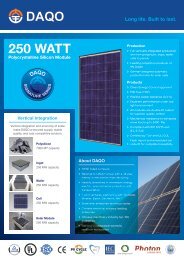
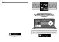
1.4 Typical I-V Characteristics at STC<br />
2.50<br />
I-V P-V Characteristics by Irradiance<br />
Model: SF<strong>150</strong>-L<br />
Condition: AM1.5 25°C<br />
250<br />
2.00<br />
1.50<br />
1000W/m 2<br />
800W/m 2<br />
600W/m 2<br />
200<br />
<strong>150</strong><br />
1.00<br />
0.50<br />
400W/m 2<br />
200W/m 2<br />
100<br />
50<br />
0.00<br />
0<br />
0 20 40 60 80 100 120<br />
Voltage [V]<br />
Typical characteristics<br />
SAB12-0160_02_Product_Data_Sheet_SF<strong>150</strong>-L 1
Current (A)<br />
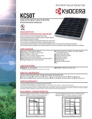
1.5 Thermal Characteristics<br />
NOCT 47°C<br />
Temperature Coefficient of Isc α +0.01 % / K<br />
Temperature Coefficient of Voc β -0.30 % / K<br />
Temperature Coefficient of Pmax δ -0.31 % / K<br />
These thermal characteristics are typical data.<br />
3.00<br />
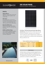
I-V Characteristics by Temperature<br />
Model : SF<strong>150</strong>-L<br />
Condition : AM 1.5 1000W/m 2<br />
2.50<br />
2.00<br />
1.50<br />
75°C<br />
1.00<br />
0.50<br />
50°C<br />
25°C<br />
0°C<br />
0.00<br />
0 20 40 60 80 100 120 140<br />
Voltage (V)<br />
Typical characteristics<br />
1.6 Characteristics for System Design<br />
Maximum System Voltage Vsys 1,000V DC (UL 600V DC)<br />
Limiting Reverse Current Ir 7A<br />
Maximum Series Fuse Rating Isf 4A<br />
SAB12-0160_02_Product_Data_Sheet_SF<strong>150</strong>-L 2
2. Mechanical Characteristics<br />
Dimensions (L x W x H)* 3<br />
1,257 x 977 x 35 mm (49.5 x 38.5x 1.4 inch)<br />
Weight<br />
20 kg (44.1 lbs)<br />
Module Operating Temperature -40°C to 85°C<br />
Application Class on IEC61730<br />
Class A<br />
Fire Safety Class on IEC61730<br />
Class C<br />
Safety Class on IEC61140<br />
II<br />
Snow Load (to the front of the <strong>module</strong>) * 4 2,400 Pa (IEC61646) / 1,600Pa design load (UL1703)<br />
Wind Load (to the back of the <strong>module</strong>) 2,400 Pa (IEC61646) / 1,600Pa design load (UL1703)<br />
Cell Type<br />
Front Cover<br />
Encapsulant<br />
Back Sheet<br />
Frame<br />
Edge Sealant<br />
Junction Box<br />
Adhesive<br />
Output Cables (Conductor)<br />
Cable lengths (Symmetrical)<br />
Connectors<br />
CIS substrate glass (Cadmium free)<br />
3.2 mm Clear tempered glass<br />
EVA<br />
Weatherproof plastic film (Color: black & silver)<br />
Anodized aluminum alloy (Color: black)<br />
Butyl rubber<br />
Protection rating: IP67 (with Bypass diode)<br />
Silicone<br />
2.5 mm 2 /14AWG (Halogen free)<br />
1,200 mm (47.2 inch)<br />
MC4 compatible<br />
Note *3 Dimensional tolerances are stated in the drawing section of this product data sheet.<br />
Note *4 UL: 1.5 times design load is applied to the <strong>module</strong>. Accordingly, 2,400 Pa (50.1lbs /ft 2 ) is loaded to test the 1,600 Pa<br />
(33.4 lbs /ft 2 ) UL design load<br />
3. Qualifications and Compliance<br />
IEC 61646 / IEC 61730 / UL1703 certified<br />
CE-Mark Declaration<br />
No conflict with ROHS<br />
4. Disclaimers<br />
Copyright for all material appearing on this Product Data Sheet belongs to <strong>Solar</strong> <strong>Frontier</strong> K.K. (“<strong>Solar</strong> <strong>Frontier</strong>”). <strong>Solar</strong><br />
<strong>Frontier</strong> reserves the right, at its sole discretion, to change, modify, add, or delete portions of the content at any time<br />
without notice, but makes no commitment to update any content which may be out of date.<br />
The data contained in this Product Data Sheet indicates nominal data of our products as of the shipment of the<br />
products. Any warranty with respect to the quality or performance of our products will be provided only based on a<br />
limited warranty certificate separately issued by <strong>Solar</strong> <strong>Frontier</strong>. See the Installation and Maintenance Guide or contact<br />
the Technical Service for further information on approved installation and use of this product.<br />
5. Contact<br />
<strong>Solar</strong> <strong>Frontier</strong> K.K.<br />
Address: 2-3-2 Daiba, Minato-ward Tokyo, 135-8074 JAPAN<br />
Email: info@solarfrontier.co.jp<br />
Website: www.solar-frontier.com<br />
SAB12-0160_02_Product_Data_Sheet_SF<strong>150</strong>-L 3
6. Module Drawing<br />
SAB12-0160_02_Product_Data_Sheet_SF<strong>150</strong>-L 4
SAB12-0160_02_Product_Data_Sheet_SF<strong>150</strong>-L 5