Olympus System Microscope CH Repair Manual
Olympus System Microscope CH Repair Manual
Olympus System Microscope CH Repair Manual

You also want an ePaper? Increase the reach of your titles
YUMPU automatically turns print PDFs into web optimized ePapers that Google loves.
OLYMPUS SYSTEM MICROSCOP<br />
MODEL <strong>CH</strong><br />
REPAIR MANUA<br />
OLYMPUS
CONTENTS<br />
1. REPAIR TOOLS AND GREASE ..<br />
2. EXPLODED PARTS DIAGRAMS....................•......•.....•..... 2<br />
3. DISASSEMBLING PROCEDURES FOR <strong>CH</strong>A·F-3 6<br />
4. REASSEMBLING PROCEDURES FOR <strong>CH</strong>A·F-3 17<br />
5. DISASSEMBLING PROCEDURES FOR C·<strong>CH</strong> CONDENSER HOLDER 31<br />
6. REASSEMBLING PROCEDURES FOR C·<strong>CH</strong> CONDENSER HOLDER 34<br />
7. DISASSEMBLING PROCEDURES FOR C-CL LIGHT EXiT 37<br />
8. REASSEMBLING PROCEDURES FOR C-CL LIGHT EXiT 38<br />
9. OVERALL REASSEMBLY AND ADJUSTMENT 38<br />
10. DISASSEMBLING AND REASSEMBLING PROCEDURES FOR <strong>CH</strong>A-F 40<br />
11. DISASSEMBLING AND REASSEMBLING PROCEDURES FOR C-MVR -45
TO OLYMPUS MICROSCOPE SERVICING PERSONNEL<br />
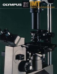
<strong>CH</strong> Series <strong>Microscope</strong> is widely used throughout the world for training students and inspecting various<br />
specimens. Since this microscope is frequently operated for routine microscopy, it is to be often repaired<br />
at your shop. Accordingly, this manual should be highly helpful for servicing personnel.<br />
As you know, the coarse and fine adjustment mechanism of <strong>CH</strong> Series is nearly the same as that of the<br />
preceding BH Series. The servicing personnel having experience in repair of BH Series can therefore easily<br />
repair <strong>CH</strong> Series.<br />
However, attention must be paid to the fact that <strong>CH</strong> Series has undergone modification of its coarse adjustment<br />
guide, and accordingly this series currently uses new and old types of coarse adjustment guides.<br />
The old and new types of the current <strong>CH</strong> Series can be discriminated from each other by a vertical line<br />
as illustrated below. The old one was switched to the new one at the beginning of 1979.<br />
<strong>CH</strong>A-F (Old type)<br />
AA872000<br />
Vertical line marked<br />
<strong>CH</strong>A-F-3 (New type)<br />
AA819500<br />
This manual describes repairing procedures for the new type of microscope first, and those for the old type<br />
separately at the last part.<br />
<strong>CH</strong> Series adopts the binocular tube which is quite the same as that of the BH Series. For repairing procedures<br />
of the binocular tube, reference should therefore be made to the repair manual for BH Series.<br />
"R ight side" and "left side" used in descriptions denote those as seen by the microscopist in his observing<br />
position.<br />
In addition, the mechanical stage of Model IMT is nearly the same as that of <strong>CH</strong>-MVR, and the servicing<br />
personnel should refer to this manual.
Requisites for repairs:<br />
1. First of all, ascertain what parts of the microscope the .user or owner of which wishes you to repair.<br />
2. Never fail to check the entire function of the microscope before you commence its repair.<br />
a) Find out what prts are defective and how much they are damaged.<br />
b) Prior to repair, think of the best possible order of disassembling the defective parts in a most<br />
efficicent way.<br />
3. After completing the repair, check the functions of not only the re-assembled parts but also the entire<br />
microscope to make sure no defect should be left unremedied.<br />
4. Be carefu I not to deform repair parts during the assembly; make it practice to use tools and jigs<br />
specified for purpose.<br />
5. Make repairs promptly and accurately.
1. REPAIR TOOLS AND GREASE<br />
1-1 Regular Tools<br />
OTOOll<br />
OT0015<br />
OT0016<br />
OT0017<br />
OT0023<br />
OT0035<br />
OT0044<br />
OT0216<br />
OT0317<br />
OT1027<br />
OTl131<br />
OTl141<br />
1-2 Grease<br />
OT2006<br />
OT2008<br />
OT2010<br />
OT2012<br />
1-3 Special Jigs and Tools<br />
Set of screwdrivers (6 pes.)<br />
Phillips screwdriver (medium size)<br />
Phillips screwdriver (large size)<br />
Screwdriver (small size)<br />
Handle of small size of Phillips screwdriver<br />
Tweezers (special made)<br />
Torque screwdriver<br />
Set of Allen wrenches (8 pes.)<br />
Thickness gauge<br />
Alon Alpha<br />
Shellac (20 g)<br />
Phillips screwdriver tiP. using OT0023<br />
KKACU2.5 Allen wrench with straight handle<br />
KKAA7828 Pin face wrench for fine adjustment<br />
K KAA8716 Pin face wrench<br />
KC-2010 Tool for holding gear<br />
8-KC0026 Jig for receptacle balls<br />
8-KC0027 Spoon for balls<br />
B-KC0028 Jig for receptacle balls<br />
SKN0003 Gauge for checking stage tilt alignment<br />
<strong>CH</strong>KC0001 Jig for adjusting movement of C-MVR<br />
<strong>CH</strong>KC0002 Jig for adjusting movement of C-MVR<br />
<strong>CH</strong>KC0003 Support frame for C-MVR<br />
-1-
Fig.34<br />
Fig. 3-5<br />
Fig. 3-6<br />
AA819800<br />
, ' . '1' . .. •<br />
.. ... ' j-<br />
3-3 Disassemble Condenser holder C-<strong>CH</strong> by remov·<br />
ing three Screws AB3xlOSA and three Washers<br />
AA800300.<br />
3-3-1 Rack up the condenser holder to its upper<br />
limit. Remove Screw AB3xl0SA which is<br />
visible through the notch formed under<br />
Holder AA870600. (See Fig. 3-4)<br />
3-3-2 Rack down the condenser holder to its lower<br />
limit and then remove two Screws AB3x 1OSA.<br />
(See Fig. 3-5)<br />
3-4 Disassembling procedures for coarse adjustment<br />
guide.<br />
NOTE:<br />
For disassembling procedures of the coarse<br />
adjustment guide of <strong>CH</strong>A-F (old type), see 10-1<br />
of th is manual.<br />
3-4-1 Detach two Fixing pieces AA819800 by<br />
removing two Screws CU K2.6x 10SA.<br />
-7-<br />
(See Fig. 3-6)
Fig. 3-12<br />
Fig. 3-13<br />
Fig. 3-14<br />
AA785000<br />
-10 -<br />
3-4-8 Disconnect Wire AA955600 from Arm<br />
AA819500. (See Fig. 3-12)<br />
3-5 Disassembling procedures for coarse and fine<br />
adjustment knobs.<br />
3-5-1 Disassemble the fine adjustment knobs in the<br />
procedures given below:<br />
a) Detach right and left Plates AA785000.<br />
They can be detached with tweezers fitted<br />
into the notches formed in the plates.<br />
(See Fig. 3-13)<br />
b) Remove Screws AB3x6SA from the right<br />
and left fine adjustment knobs.<br />
To remove the screws, fit the alien wrench<br />
into them and turn counterclockwise.<br />
(See Fig. 3-14)
Fig. 3·15<br />
Fig. 3·16<br />
Fig. 3·17<br />
AA784400<br />
- 11 -<br />
c) Pull out the fine adjustment knobs in both<br />
directions. (See Fig: 3-15)<br />
3-5-2 Detach Washer AA784400. (See Fig. 3-16)<br />
3-5-3 Detach Spring AA795500.<br />
(See Fig. 3-17)
Fig. 3·18<br />
Fig. 3-19<br />
Fig. 3-20<br />
CUK2_6x5SA<br />
AA800200<br />
•<br />
AA784700<br />
-12-<br />
3-5-4 Aher removing three Screws CUK2.6x5SA<br />
and three Washers AA800200, pull out leh<br />
Coarse adjustment knob AA784700.<br />
(See Fig. 3-18)<br />
3-5-5 Disassemble Shaft holder AA872200 in the<br />
following procedures:<br />
a) Loosen two Screws ACU3x6SA.<br />
(See Fig. 3-19)<br />
b) While holding the right coarse adjustment<br />
knob by hand, turn the shaft holder a little<br />
counterclockwise with pliers. After the shaft<br />
holder is loosened a little, turn the coarse<br />
adjustment knob clockwise. (See Fig. 3-20)<br />
NOTE:<br />
The pre-focusing lever should be unlocked in<br />
advance.
Fig. 3-21<br />
Fig. 3-22<br />
Fig. 3-23<br />
AA800200<br />
AA784600<br />
-13 -<br />
3-5-6 Remove Spring AA784200. (See Fig. 3-21)<br />
3-5-7 Pullout the right coarse adjustment knob in<br />
the direction indicated by arrow.<br />
(See Fig. 3-22)<br />
3-5-8 Disassel]lble the right coarse adjustment knob<br />
unit in the following procedures:<br />
a) 8y removing three Screws CUK2.6x5SA and<br />
Washers AA800200, disassemble Coarse<br />
adjustment knob AA784600. (See Fig. 3-23)
Fig. 3-24<br />
Fig. 3·25<br />
Fig. 3·26<br />
AA787800<br />
ZJ808600<br />
KC-2010<br />
AA783000<br />
ZJ808700<br />
-14 -<br />
b) By removing three Screws CUK2.6x5SA,<br />
detach Circular plate AA783000.<br />
(See Fig. 3-24)<br />
c) Detach gears<br />
AA787800.<br />
ZJ808600, ZJ808700 and<br />
(See Fig. 3-25)<br />
3·5-9 Disassemble Pinion unit ZJ808900 in the<br />
following procedures:<br />
a) Set Tool KC-2010 on the right Gear ZJ·<br />
808900, and set Tool KKAA7828 on the left<br />
Nut AA782800. (See Fig. 3-26)<br />
b) Remove the nut by turning the tool counter·<br />
clockwise.<br />
NOTE:<br />
The nut is fixed with adhesive agent.<br />
The bearing unit contains 30 8alls B 1/16.
Fig. 3-27<br />
Fig. 3-28<br />
Fig. 3-29<br />
AA783700<br />
\<br />
cl<br />
d)<br />
Pullout Pinion ZJ808900<br />
indicated by arrow.<br />
Remove 8alls 8 1/16.<br />
in the direction<br />
(See Fig. 3-27)<br />
3-5-10 After removing two Screws CUK3x6SA and<br />
Screw CSK3x6SA, dismount the pinion<br />
bearing.<br />
It can be pulled out in the direction indicated<br />
by arrow after the screws have been removed.<br />
(See Fig. 3-28)<br />
3-5-11 Disassemble the pinion bearing in the procedures<br />
given below:<br />
-15-<br />
a) Detach Washer AA783700. (See Fig. 3-29)
Fig. 3-30<br />
Fig. 3·31<br />
Fig. 3·32<br />
AA783800<br />
AA941500<br />
-16-<br />
b) Detach Spring AA783800. (See Fig. 3-30)<br />
c) Remove Knob AA941500 by turning it<br />
clockwise (in the direction indicated by<br />
arrow). (See Fig. 3-31)<br />
3·5-12 Disassemble the pre-focusing lever in the<br />
following procedures:<br />
a) Remove Stopper AA001500. (See Fig. 3-32)
Fig. 3-33<br />
Fig. 3-34<br />
AA784100<br />
AA941600<br />
4. REASSEMBLING PROCEDURES FOR <strong>CH</strong>A-F-3<br />
Fig. 4-'<br />
AA941500<br />
- 17-<br />
b) Remove Lever AA941600 by turning it<br />
counterclockwise. (See Fig. 3-33)<br />
NOTE:<br />
Lever ZJ850000<br />
three parts:<br />
Lever<br />
Ring<br />
Outer ring<br />
AA941600<br />
AA784100<br />
AA784000<br />
consists of the following<br />
c) Detach Ring AA784100. (See Fig. 3·34)<br />
4-1 Reassemble the coarse adjustment knob.<br />
4-1-1 Reassemble the pinion bearing unit in the<br />
following procedures:<br />
a) Reassemble Knob AA783800 with Bearing<br />
AA782200.<br />
Apply Grease OT2006 to the thread.<br />
(See Fig. 4·1)
Fig. 4-2<br />
Fig_ 4-3<br />
Fig_ 4-4<br />
AA783700<br />
-18 -<br />
b) Apply Grease OT2006 to the thread crests of<br />
Spring AA783800 and reassemble it.<br />
(See Fig. 4-2)<br />
c) Apply Grease OT2006 to Washer AA783700<br />
and reassemble it. (See Fig. 4-3)<br />
4-1-2 Reassemble the pinion bearing with Arm<br />
AA819500 by using two Screws CUK3x6SA<br />
and Screw CSK3x6SA. (See Fig. 4-4)
Fig.4·5<br />
ZJ808900<br />
8·KC0026<br />
Fig.4-6<br />
Fig. 4·7<br />
}Thread<br />
ZJ808900<br />
B·KCOO27<br />
B 1/16<br />
/<br />
-19 -<br />
4·1·3 Reassemble Pinion shaft ZJ808900 in the<br />
procedures given below:<br />
a) Apply Grease OT2012 to the Pinion shaft<br />
ZJ808900. (See Fig. 4·5)<br />
NOTE:<br />
Take care not to apply grease to the thread.<br />
b) Set 30 Balls B 1/16 into the pinion shaft.<br />
(1) Set Jig B·KC0026 on the pinion shaft.<br />
(2) Apply Grease OT2012 to the 30 balls and<br />
set them into Jig B-KC0027.<br />
(3) Drop the balls in direction (A).<br />
(4) Pull out Jig B·KC0026 in direction (B).<br />
(See Fig. 4-6)<br />
c) Reassemble the pinion shaft with the bearing.<br />
(1) With the microscope stand kept upright,<br />
insert the pinion shaft while taking care<br />
not to drop the balls.<br />
(2) Fell down the microscope stand while<br />
holding the pinion shaft so as not to drop<br />
the balls. (See Fig. 4·7)
Fig. 4-8<br />
Fig. 4-9<br />
Fig. 4-10<br />
B·KC0028<br />
I,<br />
AA782800<br />
-20-<br />
d) Set the 30 Balls B 1/16 by using Jig B-KC<br />
0028.<br />
(1) Set Jig B-KC0028 in position.<br />
(See Fig. 4-8)<br />
(2) While taking care not to apply grease to<br />
the thread of Pinion shaft ZJ808900. set<br />
the balls by using tweezers. (See Fig. 4·9)<br />
(3) Remove Jig B·KC0028.<br />
NOTE:<br />
Take sufficient care to prevent grease to<br />
be applied to the thread of the pinion<br />
shaft.<br />
e) Reassemble Nut AA782800 and tighten it to<br />
such a degree as to prevent the balls from<br />
dropping out. (See Fig. 4-10)
Fig. 4·14<br />
Fig. 4-15<br />
Fig.4-16<br />
ZJ808600<br />
ZJ808700<br />
b) Reassemble Lever AA941600 by screwing<br />
it clockwise as far as it can turn.<br />
(See Fig. 4-14)<br />
c) Reassemble Stopper AA001500.<br />
(See Fig. 4-15)<br />
4-1-5 Reassemble the right coarse adjustment<br />
knob:<br />
a) Reassemble Gear mount with Gears AA·<br />
787800, ZJ808600 and ZJ808700.<br />
Grease OT2012 should preliminarily be<br />
applied to the shafts and th read of the gears.<br />
(See Fig. 4-16)<br />
- 22-
Fig. 4·20<br />
Fig. 4-21<br />
AA784200<br />
Fig. 4-22<br />
Screws AA146300 on AA784100<br />
Screws AA146300 on AA872200<br />
- 24-<br />
b) Reassemble Spring AA784200. (See Fig. 4-20)<br />
c) Reassemble 8earing AA782200.<br />
(1) Fit Stopper screw AA 146300 located on<br />
Bearing AA872200 into the circular part<br />
attached at the other end of Spring<br />
AA784200 as shown in Fig. 4-20. While<br />
depressing the bearing lightly to the<br />
microscope stand. turn the knob clockwise<br />
as far as it can go. (Fig. 4-21)<br />
When it is stopped, ride the knob over<br />
the stopper while allowing the bearing to<br />
be a little apart from the microscope<br />
stand once again. (See Fig. 4-22)<br />
Reassembly of the coarse adjustment<br />
knob shou Id be performed in the sequence<br />
of A .... B .... C illustrated in Fig.<br />
4-22.
Fig. 4·23<br />
Fig. 4·24<br />
Fig. 4·25<br />
- 25-<br />
(2) With the bearing depressed lightiy to the<br />
microscope stand by hand, tighten the<br />
right coarse adjustment knob by turning<br />
it clockwise. Finally, tighten it firmly<br />
while holding the bearing with pliers or<br />
the similar tool. (See Fig. 4-23)<br />
NOTE:<br />
Coarse adjustment knob AA784600 can·<br />
not turn smooth unless Gear ZJ808900<br />
assembled in the gear mount is engaged<br />
properly with Pinion ZJ808900 in<br />
tightening the knob.<br />
(3) Tighten two Setscrews ACU3x5SA on<br />
8earing AA872200. (See Fig. 4·24)<br />
4-1·7 Reassemble Coarse adjustment knob AA·<br />
874700 with three Screws CU K2.6x5SA<br />
and three Washers AA800200. (See Fig. 4·25)
Fig. 4-29<br />
Fig. 4-30<br />
Fig. 4-31<br />
AA819600<br />
AA819900<br />
c) Tighten right and left Screws AB3x6SA_<br />
(See Fig. 4-29)<br />
4-1-11 Reassemble right and left Plates AA785000.<br />
(See Fig. 4·30)<br />
4-2 Reassembling procedures for coarse adjustment<br />
guide.<br />
4-2-1<br />
a)<br />
- 27-<br />
NOTE:<br />
For reassembling the coarse adjustment guide of<br />
<strong>CH</strong>A-F (old type), proceed to 10-2 of this<br />
manual.<br />
Reassemble Inner guide unit AA819600.<br />
Temporarily reassemble Rack AA819900<br />
with Inner guide AA819600. (See Fig. 4-31)
Fig. 4-32<br />
Fig. 4·33<br />
Fig.4-34<br />
- - ----------<br />
/<br />
AB000500 3PSK 1.7x5SA<br />
AA819700<br />
AB000500<br />
3PSK1.7x5SA<br />
- 28-<br />
b) Reassemble two Wires AB000500 with Inner<br />
9uide AA819600 by using two Screws 3PSK<br />
1.7x5SA and apply Grease OT2010.<br />
(See Fig. 4-32)<br />
4-2-2 Reassemble two Wires AB000500 with Inner<br />
guide AA819700 by using two Screws 3PSK<br />
1.7x5SA and apply Grease OT2010.<br />
(See Fig. 4-33)<br />
4-2-3 Connect four Wires AA955600 to the guide<br />
of Arm AA819500.<br />
Apply grease OT2010 to the wires and bond<br />
them for connection. (See Fig. 4-34)
Fig. 4-35<br />
Fig. 4-36<br />
Fig. 4-37<br />
ABB77600<br />
AAB19700<br />
B 5/32<br />
- 29-<br />
4-2-4 Mount Casing AA872600 and eight Balls<br />
B 5/32. (See Fig. 4-35)<br />
o Apply Grease OT2010 to the balls in<br />
advance.<br />
o The casing shou Id be centered with the<br />
pinion.<br />
4-2·5 Reassemble the inner guide unit prepared in<br />
step 4-2-1 above. (See Fig. 4-36)<br />
4-2-6 Reassemble the inner guide unit prepared in<br />
step 4-2-2 above_<br />
a) Mount Casing AA872600 and eight Balls<br />
B 5/32 on the Inner guide AA819700.<br />
(See Fig. 4-37)<br />
This step is quite similar to 4-2-4 above_
Fig.4-38<br />
Fig. 4·39<br />
Fig.440<br />
AB3xl0SA<br />
b)<br />
4-2-7 Reassemble two Fixing pieces AA819800 by<br />
using Screw CUK2.6x10SA. (See Fig. 4-391<br />
4-2-8<br />
-30-<br />
a)<br />
b)<br />
Reassemble the Inner guide in alignment with<br />
that reassembled in step 4-2-5 above.<br />
(See Fig. 4-38)<br />
NOTE:<br />
The inner guide should be fixed by tightening<br />
Screw AB3x 1OSA, and then loosened about<br />
haifa turn (180°).<br />
NOTE:<br />
The screw shou Id be tightened to such a<br />
degree that the guide is free from play.<br />
Adjust Rack AA819900.<br />
Loosen about half a tu rn two Screws AB3x<br />
10SA which are used for fixing the rack.<br />
A fter positioning the rack snugly by moving<br />
the inner guide up and down with the coarse<br />
adjustment knob, firmly tighten two Screws<br />
AB3x1OSA.<br />
4-2-9 Adjustment of inner guide unit<br />
a) Adjust the inner guide unit to the center of its<br />
movable range. (See Fig. 4-40)
Fig.441<br />
Fig. 442<br />
5. DISASSEMBLING PROCEDURES FOR C-GH CONDENSER HOLDER<br />
Fig. 5-1<br />
b) By using a screwdriver or tweezers, adjust the<br />
casing to the center of the inner guide unit.<br />
(See Fig. 4-41)<br />
c) By using Torque screwdriver OT0044, tighten<br />
two Setscrews GUK2.6x10SA for the fixing<br />
piece. (See Fig. 4-42)<br />
Tightening torque: 800 g-cm<br />
d) Apply Shellac OT1131 to the screws to<br />
prevent loosening.<br />
e) Finally fix inner guide AA819700 by tightening<br />
three Screws AB3x10SA.<br />
5-1 By removing two Screws GUK3x10SA, dismount<br />
left Dovetail AA870800. (See Fig. 5-1)<br />
-31-
Fig. 5·2<br />
Fig. 5-3<br />
Fig. 5-4<br />
klA008000<br />
AA870800<br />
O''+-- CUK3x5SA<br />
-32 -<br />
5-2 By removing two Screws CUK3x10SA. dis·<br />
mount right Dovetail AAB70BOO. (See Fig. 5-2)<br />
5-3 Dismount the condenser holder. (See Fig. 5-3)<br />
5-4 Disassembling procedures for condenser holder.<br />
5-4·1 By removing two Screws CUK3x5SA. dis·<br />
mount Rack AA870700. (See Fig. 5-4)
AA870900<br />
Fig. 5-5 NOTE:<br />
Fig. 5-6<br />
Fig. 5-7<br />
AA786300<br />
AA871100<br />
ACU2.6x3SA<br />
-33 -<br />
5-4-2 Detach Sleeve AA870900. (See Fig. 5-5)<br />
NOTE:<br />
Sleeve AA870900 should be detached to<br />
correct the following defects only:<br />
(1) Miscentering of condenser<br />
(2) Breakage of Sleeve AA870900<br />
a) Remove Setscrew AA008000.<br />
b) Loosen three Screws NU3x6SA_<br />
c) Detach Sleeve AA870900.<br />
5-4-3 Remove Condenser height adjusting screw<br />
HU5x14SA.<br />
The height adjusting screw should be removed<br />
only when the condenser height is misadjusted.<br />
a) Remove Nut NN5SA.<br />
b) Remove Screw HU5x14SA.<br />
(See Fig. 5-5)<br />
5-4-4 Disassemble Pinion AA871100. (See Fig. 5-6)<br />
5-4-5 Detach Knob AA786300 from Pinion AA<br />
871100 by removing two Screws ACU2.6x<br />
3SA. (See Fig. 5-7)
Fig. 5-8<br />
Fig. 5-9<br />
5-4-6 Dismount Pinion holder AA871200 by<br />
removing two Screws CUK3x5SA.<br />
(See Fig. 5-8)<br />
5-4-7 Detach Stage plate AA871800 by removing<br />
four Screws CUK4x10SA. (See Fig. 5-9)<br />
NOTE:<br />
CUK4xl0SA The stage plate should be detached only when<br />
6_ REASSEMBLING PROCEDURES FOR C-<strong>CH</strong> CONDENSER HOLDER<br />
Fill- 6-1<br />
-34-<br />
it is defective or its perpendicularity is improper.<br />
6-1 Reassemble Stage plate AA871800 with Block<br />
AA870500 by using four Screws CUK4x10SA.<br />
(See Fig. 6-1)
Fig. 6-2<br />
Fig. 6·3<br />
Fig.64<br />
NU3x6SA<br />
6-2 Reassemble Pinion holder AA871200 by using<br />
two Screws CUK3x5SA. (See Fig. 6-2)<br />
6-3 Set Pinion AA8711 00 in position. (See Fig. 6-3)<br />
6-4 Reassembling procedures for condenser holder<br />
unit.<br />
6-4-1 Reassemble Sleeve AA870900 with Condenser<br />
holder AA870600 by using three<br />
Screws NU3x6SA. (See Fig. 6-4)<br />
6-4-2 Reassemble Setscrew AA008000.<br />
- 35-
Fig. 6-8<br />
Fig. 6-9<br />
/'<br />
AA870800<br />
6-8 Reassemble left Dovetail AA870800 by using<br />
two Screws CU K3x 10SA and two Washers SW<br />
3SA. (See Fig. 6-8)<br />
While pushing the dovetail uniformly in the<br />
direction indicated by arrows, tighten the<br />
screws.<br />
6-9 Reassemble Knob AA876300 by using two<br />
Screws ACU2.6x3SA.<br />
The knob should be apart about 2 mm.<br />
(See 6-9)<br />
6-10 Check the condenser holder for its vertical<br />
motion.<br />
6-10-1<br />
7. DISASSEMBLING PROCEDURES FOR C-CL LIGHT EXIT<br />
1L--_AA290200<br />
a)<br />
b)<br />
Check the dovetail for its play.<br />
When the tip of the condenser holder is<br />
swung in the right-left direction, play must<br />
not be felt by hand.<br />
If the dovetail plays, tighten the two screws<br />
firmly while depressing the left dovetail<br />
sufficiently in the direction indicated by<br />
arrow. (See step 6-8 above)<br />
7-1 Remove Ring AA871600.<br />
NOTE:<br />
The ring is bonded at one point with Araldite.<br />
If it cannot be loosened with the Pin face<br />
wrench KKAA8716, cut off Araldite by using<br />
tweezers or the similar tool.<br />
7-2 Disassemble the lens system:<br />
Lens LA410800<br />
- 37-<br />
Ring AA290100<br />
Filter LP072100<br />
Ring AA290200<br />
Lens LA510900
Sreciman<br />
B2KC0010-<br />
Fig. 9-3<br />
9-3 Reassemble Light exit C-CL by using three<br />
Screws CUK3x6SA.<br />
NOTE:<br />
The notches formed in the light exit must be<br />
positioned on the front and rear as shown in<br />
Fig. 3-3.<br />
9-4 Reassemble Electric base plate C-BDA.<br />
(See Fig. 3-2)<br />
9-5 Check and adjustment of fine adjustment<br />
sensitivity.<br />
9-5-1 Set the following accessories and checking<br />
components in the microscope as shown<br />
in Fig. 9-3.<br />
<strong>Microscope</strong> tube}<br />
Objective 40x<br />
Eyepiece lOx<br />
Condenser<br />
Need not be of<br />
specific types<br />
Specimen (matched with objective 40x)<br />
Block B2KC0010<br />
9-5-2 Check fine adjustment sensitivity in the<br />
following procedures:<br />
a) Bring the specimen into focus and read<br />
indication on the fine adjustment scale.<br />
b) Turn the fine adjustment knob ±25 Il (10<br />
divisions) and bring the specimen into focus<br />
once again. Then read indication on the<br />
fine adjustment scale once again.<br />
Difference between readings obtained in step<br />
a) and b) must be within 1.5 divisions.<br />
c) Remove Block B2KC0010, and then carry out<br />
steps a) and b) above.<br />
9-5-3 When the standard is not satisfied:<br />
a) Check the pinion shaft (assembled in 4-1·3)<br />
for its assembled condition and parts.<br />
b) Check the right coarse adjustment knob<br />
(assembled in 4·1-5) for its assembled condi·<br />
tion and parts (especially the gears).<br />
c) Check the right coarse adjustment knob unit<br />
for its assembled condition.<br />
- 39-<br />
For details, refer to the steps mentioned in the<br />
above parentheses.
10. DISASSEMBLING AND REASSEMBLING PROCEDURES FOR <strong>CH</strong>A-F (OLD TYPE)<br />
Fig. 10·1<br />
Fig. 10-2<br />
Fig. 10-3<br />
I<br />
10-1-1 Loosen two Adjusting screws HU3x4SA on<br />
the left coarse adjustment guide.<br />
(See Fig. 10-1)<br />
10-1-2 Dismount left Outer guide AA872400 by<br />
removing three Screws AB3x lOSA.<br />
(See Figs. 10-2, 10-3)<br />
-40-
Fig. 104<br />
Fig. 10-6<br />
Fig. 10-6<br />
- 41 -<br />
10-1-3 Remove eight Balls B 5/32, Casing AAB72600<br />
and Inner gu ide AA872500. (See Fig. 10-4)<br />
10-1-4 Remove eight Balls B 5/32 and Casing AA-<br />
872600. (See Fig. 10-5)<br />
10-1-5 Disassemble right Outer guide AA872400 by<br />
removing three Screws AB3xl0SA.<br />
(See Fig. 10-6)
Fig. 10·16<br />
-<br />
-;.<br />
10·2-8 Adjust the guide<br />
a) Tighten two Adjusting screws HU3x4SA by<br />
using Torque screwdriver OT0044.<br />
(See Fig. 10-16)<br />
11. DISASSEMBLING AND REASSEMBLING PROCEDURES FOR C·MVR<br />
J<br />
QJ<br />
Fig.11·1<br />
•<br />
Fig. 11·2<br />
o<br />
AA877900<br />
AA878000<br />
---------- --------<br />
o<br />
3PSK2x6SA<br />
PUK2x3SA<br />
-45-<br />
Tightening force: 700 g·cm<br />
b) Finally tighten three Screws AB3x10SA on<br />
the outer gu ide.<br />
NOTE.<br />
For later steps, proceed to Section 5 of this<br />
manual.<br />
11-1 Disassembly procedure of East-West Drive<br />
guide<br />
11·1·1 Remove Specimen holder unit by drawing<br />
4 Screws 3PSK2x6SA. (See Fig. 11·1)<br />
11-1-2 Remove Rack AA877900 by drawing 3<br />
Screws 3PUK2x6SA. (See Fig. 11-1)<br />
11-1-3 Remove East·West Graduated plate AA<br />
878000 by drawing 3 Screws PUK2x3SA.<br />
(See Fig. 11-2)
Fig. 11-6<br />
AA952200<br />
AA502600<br />
Fig. 11·7<br />
AA952200<br />
AA952000<br />
Fig. 11-8<br />
AA879700<br />
<strong>CH</strong>KC0003<br />
AA952200<br />
o<br />
<strong>CH</strong>KC0003<br />
B 1/8<br />
__--81/8<br />
o<br />
AA879700<br />
o<br />
AA502600<br />
-47 -<br />
11·2-3 Place the reassembled East-West Drive guide<br />
on Support frame <strong>CH</strong>KCOOO3.<br />
(See Fig. 11-6)<br />
11-2-4 Place Casing AA879700 in the middle of<br />
East-West Drive guide AA952000 and set<br />
9 Balls B-l/8 into the holes of Casing.<br />
(See Fig. 11-6)<br />
NOTE:<br />
Apply a small amount of Grease OT2008<br />
to these Balls.<br />
11-2-5 Place Casing AA879700 in the middle of<br />
Feed plate AA952200 and set 9 Balls.<br />
(See Fig. 11-7)<br />
NOTE:<br />
o Stopper AA502600 can be used as a mark<br />
to center Casing AA879700 on Feed<br />
plate with.<br />
o Apply a small amount of Grease OT2008<br />
to Balls.<br />
11-2-6 Place Feed plate AA952200 (in step 11-24)<br />
on East-West Drive guide AA952000 (in<br />
step 11-2-3).<br />
NOTE:<br />
Align the positions of upper and lower<br />
Casings with each other vertically.<br />
(See Fig. 11-8)
AA952100<br />
Fig. 11·9<br />
Screwdriver<br />
Fig.11·10<br />
Adjusting knob<br />
o<br />
3PUK2x6SA<br />
AA952100<br />
CUK2.6x8SA<br />
o<br />
o<br />
AA952000<br />
"/ eJ / l AA952200<br />
AA952000<br />
AA877900<br />
Fig. 11·11<br />
AA95\OO<br />
Gl I 0 0<br />
0<br />
, I<br />
-48 -<br />
11-2-7 Reassemble East·West Drive guide AA952100<br />
temporarily with 3 Screws CUK2.6xBSA.<br />
b)<br />
c)<br />
d)<br />
NOTE:<br />
Do not clamp too tight.<br />
(See Fig. 11·9)<br />
11-2-B Set the jig <strong>CH</strong>KC0002 as shown in Fig. 11-10.<br />
11-2-9 Adjust East-West Drive guide AA952100,<br />
then clamp. (See Fig. 11-10)<br />
a) Tighten Adjusting knobs evenly so that Feed<br />
plates AA952200 have no play.<br />
NOTE:<br />
Be careful not to impair Wires by tightening<br />
Adjusting knobs too much.<br />
Clamp East-West Drive guide AA952100<br />
firmly with 3 Screws CUK2.6xBSA.<br />
Loosen Adjusting knobs.<br />
Manipulating Feed plate AA9522oo, check<br />
whether it still has uneven stiffness, irregular<br />
movements or play.<br />
(1) In case of uneven stiffness, Wires are<br />
impaired. Replace.<br />
(2) In case of irregular movements, repeat<br />
steps over again from 11-2-9 (a).<br />
(3) In case of play, repeat steps over again<br />
from 11-2-9 (a).<br />
11-2-10 Assemble Rack AAB77900 with 3 Screws<br />
3PUK2x6SA. (See Fig. 11-11)<br />
a) By manipulating East-West Drive knob,<br />
check whether Rack has uneven stiffness,<br />
irregular movements or play.<br />
b) If it has stiff or erregular movements or<br />
play, adjust the position of Rack AAB779oo.
AA951600<br />
<strong>CH</strong>KC0003<br />
Fig. 11-18<br />
Fig. 11-19<br />
AA951600<br />
Cltk: COOV,J<br />
I I<br />
,1---1.,<br />
I I<br />
AA878400<br />
/<br />
AA951700<br />
- 51 -<br />
11-4-6 Reassemble Mounting base AA951700 to<br />
Specimen holder Main body AA951600_<br />
NOTE:<br />
Be careful not to disperse Balls out of<br />
position.<br />
11-4-7 Holding Mounting base reassembled in step<br />
above with the finger in position, assemble<br />
Casing and Balls as follows: (See Fig. 11-19)<br />
a) Pull out Mounting Base AA951700 in the<br />
arrow direction (-+) up to the position of<br />
Stopper and hold there with the finger.<br />
b) Insert Casing AA878400 in the arrow direction<br />
(=) until its tip enters Specimen<br />
holder Main body AA951800, then put<br />
one or two Balls B-l/8 into the holes of<br />
Casing.<br />
c) After setting other Balls into Casing, further<br />
insert Casing into Main body AA951600.<br />
NOTE:<br />
Repeat step above until 9 Balls are set in<br />
place.<br />
d) After setting all Balls in place, push the<br />
entire Casing AA878400 with the tip of a<br />
screwdriver into a same position as Casing<br />
AA878400 was positioned in step 11-4-5.
AA951600<br />
Fig. "·23<br />
AA951700<br />
Knob<br />
AA951800<br />
•<br />
•<br />
AA877300<br />
o<br />
- 53-<br />
11-4-10 Clamp Rack AA877300 with 2 Screws<br />
CUK2.6x5SA and 2 Washers KNW2.6SA.<br />
a) Insert Rack AA877300 in the arrow direction<br />
and aligning the threaded holes, clamp with<br />
screws temporarily. (See Fig. 11-23)<br />
b) 8y manipulating North-South Drive knob,<br />
check whether it has uneven stiffness,<br />
irregular movement or play.<br />
c) If any, adjust the mounting position of<br />
Rack AA877300_<br />
11-4-11 Mount Specimen holder unit with 4 Screws<br />
3PSK2x6SA.<br />
al Make adjustment between east-West Graduated<br />
plate AA878000 and Vernier AA878300.<br />
(Refer to step 11-2-13)
OLYMPUS OPTICAL CO., LTD.<br />
San-ei Building, 22-2. Nishi-shinjuku 1