Brosch. Trailer EBS (E) - wabco inform
Brosch. Trailer EBS (E) - wabco inform
Brosch. Trailer EBS (E) - wabco inform

You also want an ePaper? Increase the reach of your titles
YUMPU automatically turns print PDFs into web optimized ePapers that Google loves.
16 <strong>EBS</strong><br />
Operation of <strong>Trailer</strong> <strong>EBS</strong><br />
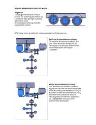
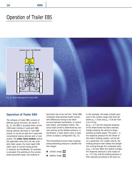
Fig. 11: Brake Management <strong>Trailer</strong> <strong>EBS</strong><br />
Operation of <strong>Trailer</strong> <strong>EBS</strong><br />
The software of trailer <strong>EBS</strong> consists of<br />
different partial functions. As shown in<br />
fig. 11, the <strong>EBS</strong> is actuated either via the<br />
CAN trailer interface if used with <strong>EBS</strong><br />
towing vehicles that have a 7-pin <strong>EBS</strong><br />
socket, or via the air pilot line if used with<br />
conventional towing vehicles with a 5-pin<br />
socket. The index value module selects<br />
the applicable value from the two available<br />
index values, the more rapid CAN<br />
index value of course having priority.<br />
If, however, the handbrake, for example,<br />
is actuated, this working on the conventional<br />
pneumatic basis, this braking requirement<br />
has to be met first. <strong>Trailer</strong> <strong>EBS</strong><br />
comprises load-sensitive brake control,<br />
with differences having to be taken<br />
account between semitrailers, or central<br />
axle trailers, and drawbar trailers. The<br />
actual load carried is determined by sensors<br />
picking up the bellows pressure. In<br />
semitrailers, a static beam valve is used,<br />
similar to today’s configuration (fig. 12).<br />
The transmitting function hose coupling<br />
pressure/braking pressure is divided into<br />
two ranges:<br />
■<br />
■<br />
contact range<br />
stability range<br />
A<br />
S<br />
In this example, the brake cylinder pressure<br />
in the contact range rises from between<br />
p m = 0 bar and p m = 0.6 bar from<br />
0 to 0.4 bar.<br />
At p m = 0.7 bar the response pressure<br />
of the wheel brake has been reached,<br />
thereby allowing the vehicle to begin<br />
building up brake power. This point, i. e.<br />
the response pressure for the whole of<br />
the trailer’s braking system, can be set<br />
via a parameter. On a laden vehicle, the<br />
braking pressure then follows the straight<br />
line running through the computed value<br />
at p m = 6.5 bar. When the vehicle is empty,<br />
the response pressure is also output at<br />
p m = 0.7 bar, and the braking pressure is<br />
then reduced according to the load car-