Brosch. Trailer EBS (E) - wabco inform
Brosch. Trailer EBS (E) - wabco inform
Brosch. Trailer EBS (E) - wabco inform

Create successful ePaper yourself
Turn your PDF publications into a flip-book with our unique Google optimized e-Paper software.
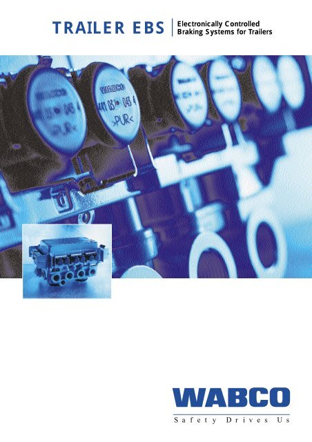
TRAILER <strong>EBS</strong><br />
Electronically Controlled<br />
Braking Systems for <strong>Trailer</strong>s<br />
S a f e t y D r i v e s U s
CONTENTS<br />
Wabco <strong>Trailer</strong> <strong>EBS</strong><br />
3<br />
Introduction<br />
<strong>EBS</strong> on the Towing Vehicle<br />
4<br />
5<br />
6<br />
6<br />
7<br />
8<br />
8<br />
9<br />
11<br />
12<br />
13<br />
13<br />
14<br />
15<br />
15<br />
16<br />
20<br />
21<br />
System Design<br />
System Functions<br />
Generating the Braking Index Valve<br />
Integration of Sustained-Action Brake<br />
Deceleration Control<br />
Brake Force Distribution<br />
Improved ABS and ASR Control<br />
<strong>EBS</strong> on the <strong>Trailer</strong><br />
System Description<br />
Redundancy Operation<br />
Components of <strong>Trailer</strong> <strong>EBS</strong><br />
<strong>EBS</strong> Relay Emergency Valve<br />
<strong>EBS</strong> <strong>Trailer</strong> Module<br />
<strong>EBS</strong> Relay Valve<br />
Axle Load Sensor<br />
Operating of <strong>Trailer</strong> <strong>EBS</strong><br />
Safety Concept<br />
Compatibility of<br />
Towing Vehicle and <strong>Trailer</strong>
INTRODUCTION 3<br />
Introduction<br />
In order to meet the demands of<br />
the growing market in the transport<br />
trade, conventional braking systems<br />
for motor vehicles and trailers have<br />
continuously been enhanced. It is<br />
expected today that operation of<br />
modern commercial vehicles is safe,<br />
efficient, comfortable and ecologically<br />
compatible.<br />
Milestones of a continuous further<br />
development of trailer braking systems<br />
have been the introduction of the EC<br />
braking system in 1973 and the development<br />
and the introduction of the anti-lock<br />
system for air-sprung commercial<br />
vehicles in 1981.<br />
The introduction of the Electronic Braking<br />
System <strong>EBS</strong> is thus the next logical step<br />
in meeting this and other requirements.<br />
<strong>EBS</strong> allows the continuing best possible<br />
synchronization of the brake forces<br />
between the towing vehicle and its trailer.<br />
<strong>EBS</strong> not only considerably enhances both<br />
vehicle and thus road safety, especially<br />
by reducing the stopping distance and<br />
improving braking stability, but also<br />
represents a major improvement in terms<br />
of economy and driving comfort by<br />
means of:<br />
■<br />
■<br />
■<br />
shorter response times and simultaneous<br />
response of wheel brakes in<br />
the whole of the tractor-trailer combination<br />
and thus a braking behaviour<br />
which is similar to that in passenger<br />
cars, regardless of the load carried.<br />
reduction of the number of individual<br />
components and their connecting<br />
elements (e. g. by eliminating the<br />
load-sensing valve, pressure ratio<br />
valves and pressure limiting valves<br />
on drawbar trailers).<br />
synchronization of brake lining wear<br />
on the individual vehicle axles.<br />
A number of improvements are achieved<br />
even when using <strong>EBS</strong> on the motor<br />
vehicle only. A further enhancement of<br />
this progress can be achieved by also<br />
using <strong>EBS</strong> on trailers. By additionally<br />
fitting disk brakes which show less<br />
thermal fading than drum brakes, further<br />
improvements can be attained, especially<br />
for extended braking processes.<br />
WABCO is planning to offer <strong>EBS</strong> also for<br />
trailers in early 1998, thereby making sure<br />
that fully electronic braking systems with<br />
future-oriented technology are also<br />
available for tractor-trailer combinations.<br />
In the coming years, this will initially cause<br />
mixed operation of towing vehicles and<br />
trailers with electronic and conventional<br />
braking systems. For this reason, compatibility<br />
in the partial braking range and<br />
for rapid retardation must be ensured.<br />
This paper deals with this problem, its<br />
background, and its solutions.<br />
Since the autumn of 1996, an electronically<br />
controlled braking system has been<br />
available as standard equipment in<br />
“ACTROS”, the new heavy-duty vehicle<br />
class from Mercedes-Benz. This <strong>EBS</strong><br />
system has been jointly developed by<br />
WABCO and Daimler-Benz.<br />
■<br />
■<br />
a considerable improvement in the<br />
compatibility between the towing<br />
vehicle and its trailer.<br />
easier installation of the braking<br />
system by the vehicle manufacturer.
4 <strong>EBS</strong><br />
<strong>EBS</strong> on the Towing Vehicle<br />
System Design<br />
7<br />
1<br />
2<br />
1<br />
10<br />
1<br />
1<br />
1<br />
5<br />
1<br />
9<br />
9<br />
8<br />
8<br />
7<br />
1 air compression system<br />
2 braking power generator<br />
3 central control unit<br />
4 proportional relay valve<br />
5 pressure modulator<br />
6 ABS<br />
7 sensors<br />
8 trailer control<br />
9 auxiliary / parking brake<br />
10 redundancy valve<br />
6<br />
4<br />
7<br />
6<br />
7<br />
TRANSMISSION ECAS RETARDER<br />
3<br />
MOTOR<br />
Fig. 1: <strong>EBS</strong> hybrid system<br />
System Design<br />
The WABCO <strong>EBS</strong> shown in fig. 1<br />
electronically controls the front axle, the<br />
rear axle, and trailer actuation. In addition<br />
to electronic braking pressure control, a<br />
pneumatic redundancy has been implemented<br />
for the front axle, the rear axle,<br />
and trailer actuation (secondary safety<br />
circuit).<br />
The so-called <strong>EBS</strong> hybrid system<br />
consists of<br />
■<br />
■<br />
■<br />
a foot braking power generator which<br />
generates both electrical and pneumatic<br />
index value signals when the<br />
brake pedal is actuated;<br />
a proportional relay valve for actively<br />
controlling the braking pressure on<br />
the front axle and the ABS control<br />
valves for ABS control on the front<br />
axle in keeping with an advanced<br />
control logic (MIR logic);<br />
a compact axle modulator with an<br />
integrated electronics module on the<br />
rear axle for individual pressure<br />
control and for picking up and<br />
evaluating the sensor signals, wheel<br />
speeds and brake lining wear;<br />
■<br />
■<br />
an electro-pneumatic trailer control<br />
valve for improving the actuation of<br />
conventionally braked trailers, allowing<br />
the trailer’s actuating pressure to be<br />
increased, reduced or automatically<br />
commenced, e. g. for control cycles<br />
caused by driving dynamics,<br />
depending on the index value;<br />
a digital data interface for actuating<br />
new trailers which have <strong>EBS</strong> fitted.<br />
The interface is integrated in an<br />
extended ABS plug-in connection to<br />
ISO 7638 (additional CAN <strong>inform</strong>ation<br />
via PINs 6 + 7);<br />
■<br />
a redundancy valve on the rear axle;
<strong>EBS</strong> 5<br />
<strong>EBS</strong> on the Towing Vehicle<br />
System Functions<br />
Switch<br />
ZFZ:<br />
AFZ:<br />
BWG:<br />
RET:<br />
PR:<br />
SR:<br />
RB:<br />
TRC:<br />
DBI:<br />
z-REG:<br />
BKV:<br />
towing vehicle<br />
trailer<br />
brake power generator<br />
retarder electronics<br />
primary retarder<br />
(engine brakes)<br />
secondary retarder<br />
friction brakes<br />
trailer control<br />
integration of<br />
sustained-action brake<br />
vehicle retardation (z)<br />
control<br />
brake force distribution<br />
Fig. 2: Brake Management Towing Vehicle <strong>EBS</strong><br />
■<br />
and a central module for overriding<br />
brake management functions, front<br />
axle and trailer actuating pressure<br />
control, picking up and evaluating the<br />
front axle sensor signals and an<br />
exchange of data with the axle modulator<br />
via the system data bus, and<br />
with other vehicle control systems via<br />
the vehicle bus.<br />
In “ACTROS”, the air processing system<br />
consisting of the air dryer, unloader valve,<br />
multiple-circuit protection valve and several<br />
pressure limiting valves has been<br />
combined in one unit.<br />
System Functions<br />
This Electronic Braking System which has<br />
now gone into series production allows a<br />
number of braking functions which result<br />
in a reduction of operating costs and<br />
improved braking comfort. The ACTROS<br />
system contains some software functions<br />
developed by Daimler-Benz themselves.<br />
The system functions described below<br />
are in keeping with the general WABCO<br />
solution and have been comprised in the<br />
respective brake management for motor<br />
vehicles and trailers. The signal flow is<br />
being shown in fig. 2. Brake management<br />
consists of several software modules.
6 <strong>EBS</strong><br />
<strong>EBS</strong> on the Towing Vehicle<br />
System Design<br />
Generating the<br />
Braking Index Value<br />
The electrical index value provided by<br />
the driver by pushing the pedal is initially<br />
converted into an index deceleration in<br />
the module for “feeling”. The index<br />
deceleration increases progressively with<br />
the amount of pedal travel. The parameters<br />
for the characteristic, also known as<br />
the “feeling curve”, can be set according<br />
to the manufacturer’s needs, or the type<br />
of vehicle operated.<br />
Integration of<br />
Sustained-Action Brake<br />
In the module for integrating the sustained-action<br />
brake, the brake force is<br />
distributed between the sustained-action<br />
and friction brakes. This distribution is<br />
achieved in such a way that the sustained-action<br />
brakes always take over a<br />
maximum of the desired brake force. This<br />
reduces wear on the friction brakes of the<br />
towing vehicle and the trailer. Whenever<br />
emergency braking is necessary, the full<br />
power of the friction brakes is then available.<br />
The integration of the sustainedaction<br />
brake thus offers a maximum in<br />
safety, economy and comfort.<br />
Regardless of the integrated sustainedaction<br />
brake actuation, the driver still has<br />
the option, e. g. when driving the vehicle<br />
down a long gradient, to activate the<br />
sustained action brake via a hand lever or<br />
foot switch independently from the<br />
friction brake. The sustained-action brake<br />
can, for instance, consist of the engine<br />
brake, a throttle brake and/or retarder.<br />
Depending on the braking needs, they<br />
are switched on one after another or<br />
simultaneously, and are either variable<br />
infinitely or in steps.
<strong>EBS</strong> 7<br />
<strong>EBS</strong> on the Towing Vehicle<br />
System Design<br />
Deceleration Control<br />
In deceleration control it is assumed that<br />
by pushing the brake pedal the driver<br />
intends to slow down the vehicle in<br />
addition to the existing vehicle deceleration<br />
caused by uphill or downhill gradients<br />
and, for instance, rolling and air resistance.<br />
For this reason, the prevailing deceleration,<br />
or fundamental deceleration, is used<br />
as a basis. The actual deceleration is<br />
picked up by the wheel speed sensors.<br />
Depending on the difference between the<br />
index and actual deceleration values, an<br />
index value adjustment is made to<br />
compute the torque for the sustainedaction<br />
brake and the service braking<br />
pressures. Irrespective of the vehicle load,<br />
deceleration control achieves an even<br />
relation between the position of the brake<br />
pedal and the vehicle’s deceleration. By<br />
means of additional measures, such as<br />
outputting the response pressures and<br />
the braking hysteresis, the driver is<br />
offered a much more direct response to<br />
any changes in the index values, i. e.<br />
improved “braking feeling”. Depending on<br />
the given index deceleration and the load<br />
carried, the braking pressures are computed<br />
individually for both the towing<br />
vehicle and its trailer, in the modules for<br />
the brake force distribution. The distribution<br />
of brake forces across the towing<br />
vehicle and its trailer is computed in the<br />
module for trailer actuation.
8 <strong>EBS</strong><br />
<strong>EBS</strong> on the Towing Vehicle<br />
System Design<br />
Fig. 3: Distribution of brake forces on a towing vehicle<br />
Brake Force Distribution<br />
Fig. 3 shows an example of the brake<br />
force distribution on a towing vehicle,<br />
both when it is laden and when it is unladen.<br />
What has been implemented is<br />
what is known as combined distribution<br />
of brake forces.<br />
It permits a combination of optimized<br />
brake force distribution for the applicable<br />
adhesion at higher index deceleration<br />
values and optimized brake force distribution<br />
in terms of lining wear at lower index<br />
deceleration values. If wear sensors have<br />
also been fitted, as in ACTROS, their signals<br />
are evaluated by the <strong>EBS</strong> and converted<br />
for adaptive lining wear control.<br />
For this purpose, the braking pressure<br />
distribution can be defined for slower<br />
deceleration in such a way that the linings<br />
on the front and rear wheels can be<br />
changed at the same times. Deceleration<br />
optimized for the applicable adhesion<br />
values in the higher braking range results<br />
in the approximately simultaneous response<br />
of ABS control on all axles.<br />
Improved<br />
ABS and ASR Control<br />
The functions of both ABS and ASR<br />
have been integrated in <strong>EBS</strong>, and further<br />
enhancements have been achieved in<br />
terms of control performance and improved<br />
comfort by means of additional<br />
<strong>inform</strong>ation on actuation of the brake,<br />
index value, axle load and braking<br />
pressure.
<strong>EBS</strong> 9<br />
<strong>EBS</strong> on the <strong>Trailer</strong><br />
Reserve<br />
3<br />
3<br />
1 relay emergency valve<br />
2 Vario Compact ABS<br />
3 ABS sensor<br />
4 load-sensing valve<br />
4<br />
Brake<br />
ISO 7638<br />
Bellows pressure<br />
1 2<br />
3 3<br />
Fig. 4: Conventional Braking System for Semitrailers<br />
<strong>EBS</strong> on the <strong>Trailer</strong><br />
Fig. 4 and 5 each show EC air braking<br />
systems widely used in Europe today. On<br />
a semi-trailer, this braking system essentially<br />
consists of a relay emergency valve,<br />
a load-sensing valve and the ABS.<br />
In the Vario-Compact System shown<br />
here, the ABS relay valves and the electronic<br />
control unit have been combined.<br />
Frequently, however, these components<br />
are fitted separately. On the drawbar<br />
trailer, another load-sensing valve, a third<br />
ABS relay valve, an adapter valve on the<br />
front axle and a pressure limiting valve on<br />
the rear axle are added to the components<br />
listed above. Although this EC braking<br />
system is now highly sophisticated,<br />
especially through the use of ABS, there<br />
is still room for the improvements listed<br />
below:
10 <strong>EBS</strong><br />
<strong>EBS</strong> on the <strong>Trailer</strong><br />
1 relay emergency valve<br />
2 Vario Compact ABS<br />
Reserve<br />
Brake<br />
3<br />
6<br />
4<br />
7<br />
4<br />
3<br />
3 ABS sensor<br />
4 load-sensing valve<br />
5 3rd ABS modulator<br />
6 adapter valve<br />
7 pressure limiting valve<br />
1<br />
Bellows pressure<br />
5<br />
Bellows pressure<br />
2<br />
ISO 7638<br />
3<br />
3<br />
Fig. 5: Conventional Braking System for Drawbar <strong>Trailer</strong>s<br />
■<br />
■<br />
■<br />
Reduction of the variety/number of<br />
components and thus installation<br />
costs for the vehicle manufacturer.<br />
Dispensing with the required air valves<br />
and their adjustment by introducing<br />
electronic control and the simple<br />
setting of parameters this permits.<br />
By using pressure control circuits<br />
which operate with a high degree of<br />
precision, it is possible to almost<br />
completely eliminate the deviations in<br />
characteristics encountered today.<br />
■<br />
■<br />
■<br />
The “electrical brake line” and<br />
electronic control can considerably<br />
improve the time response and thus<br />
contribute towards reducing the<br />
stopping distance and improving the<br />
stability of the tractor-trailer<br />
combination.<br />
Extending the diagnostic features<br />
for the whole of the braking system,<br />
including maintenance and repair<br />
instructions.<br />
Permitting more comprehensive<br />
testing after production with automatic<br />
recording of the test findings.<br />
It was these possible improvements<br />
which provided the basis for the<br />
development of an electronically<br />
controlled <strong>EBS</strong> on the trailer.
<strong>EBS</strong> 11<br />
<strong>EBS</strong> on the <strong>Trailer</strong><br />
System Description<br />
Reserve<br />
1 (5/6) 2 (5/7)<br />
3<br />
3<br />
1 <strong>EBS</strong> relay emergency valve<br />
2 <strong>EBS</strong> trailer modulator<br />
3 ABS sensor<br />
4 axle load sensor<br />
5 pressure sensor<br />
6 pressure switch<br />
7 redundancy valve<br />
Brake<br />
ISO 7638 + CAN<br />
4<br />
3<br />
3<br />
Fig. 6: <strong>EBS</strong> for Semitrailers 4S/2M<br />
System Description<br />
Fig. 6 shows the standard <strong>EBS</strong> for a<br />
3-axle semitrailer. It electronically controls<br />
lateral braking pressures. The system<br />
consists of a compact dual-circuit trailer<br />
modulator with a digital data interface to<br />
ISO 1199-2 to the <strong>EBS</strong> towing vehicle, an<br />
<strong>EBS</strong> relay emergency valve, an axle load<br />
sensor and ABS sensors. When used on<br />
drawbar trailers or semitrailers with a<br />
steering axle, a system is needed which<br />
includes an additional <strong>EBS</strong> relay valve on<br />
the steering axles, see fig. 7.<br />
Operation with new towing vehicles<br />
with <strong>EBS</strong> and extended ISO 7638<br />
plug-in connection with CAN interface.<br />
All <strong>EBS</strong> functions can be<br />
utilized. The trailer receives the index<br />
values from the towing vehicle via the<br />
data interface.<br />
<strong>Trailer</strong>s with the electronic braking system<br />
described must be compatible with both<br />
conventional towing vehicles and towing<br />
vehicles which use <strong>EBS</strong>, allowing pneumatic<br />
redundant braking in the event of<br />
<strong>EBS</strong> failure. This results in three possible<br />
types of operation:
12 <strong>EBS</strong><br />
Components of <strong>Trailer</strong> <strong>EBS</strong><br />
Operation with conventional<br />
towing vehicles with ISO<br />
7638 plug-in connection for<br />
the trailer’s ABS supply but<br />
with no CAN interface.<br />
All <strong>EBS</strong> functions can be utilized, with the<br />
exception of the transmission of the index<br />
values via the CAN data interface. The<br />
index values are provided by the pressure<br />
sensor in the relay emergency valve<br />
which picks up the actuating pressure<br />
for the trailer.<br />
Redundancy Operation<br />
In the event of a failure of the electrical<br />
voltage supply, ordinary pneumatic<br />
braking can always be achieved, although<br />
with no loadsensing or ABS functions.<br />
In redundancy operation, the time<br />
response is similar to that of today’s conventional<br />
braking systems. If the <strong>EBS</strong><br />
trailer is operated pneumatically, an improved<br />
time response is achieved since<br />
electrical sensing of the actuating pressure<br />
saves time. When used with an <strong>EBS</strong><br />
towing vehicle and actuation via CAN,<br />
the pressure in the <strong>EBS</strong> trailer builds up<br />
almost simultaneously with that in the<br />
towing vehicle.<br />
Components of <strong>Trailer</strong> <strong>EBS</strong><br />
As explained under System Description,<br />
the <strong>EBS</strong> relay emergency valve, the compact<br />
dual-circuit <strong>EBS</strong> trailer modulator<br />
which forms the heart of the system, the<br />
<strong>EBS</strong> relay valve which may be required,<br />
and the axle load sensor are the key<br />
components of trailer <strong>EBS</strong>.<br />
1 <strong>EBS</strong> relay emergency valve<br />
2 <strong>EBS</strong> trailer modulator<br />
Reserve<br />
3<br />
1<br />
8 (5/6/7)<br />
3<br />
2 (5/7)<br />
3 ABS sensor<br />
4 axle load sensor<br />
5 pressure sensor<br />
6 pressure switch<br />
7 redundancy valve<br />
8 <strong>EBS</strong> relay valve<br />
Brake<br />
ISO 7638 + CAN<br />
4<br />
3<br />
3<br />
Fig. 7: <strong>EBS</strong> for drawbar trailers 4S/3M<br />
Fig. 8
<strong>EBS</strong> 13<br />
Components of <strong>Trailer</strong> <strong>EBS</strong><br />
<strong>EBS</strong> Relay Emergency Valve<br />
(Fig. 9)<br />
Since trailers with <strong>EBS</strong> can also be used<br />
with towing vehicles that have a conventional<br />
braking system, the conventional<br />
functions of the relay emergency valve,<br />
such as the breakaway function and the<br />
check valve, continue to be required.<br />
Only the adjustable advance is dispensible<br />
since this is achieved electronically. In<br />
addition, a pressure sensor (1) for providing<br />
the braking power from the actuating<br />
pressure and a pressure switch (2)<br />
for monitoring the pressure sensor, have<br />
been integrated.<br />
Fig. 9: <strong>EBS</strong> Relay Emergency Valve<br />
to the trailer modulator<br />
2<br />
actuating<br />
pressure<br />
modulator<br />
1<br />
reservoir<br />
supply<br />
exhaust
14 <strong>EBS</strong><br />
Components of <strong>Trailer</strong> <strong>EBS</strong><br />
The pressure switch is fitted at the inlet<br />
of the brake valve, the pressure sensor<br />
at its outlet. Due to this arrangement,<br />
automatic braking is detected behind a<br />
towing vehicle with <strong>EBS</strong> in the event of<br />
the supply line breaking. This <strong>inform</strong>ation<br />
may prevent automatic braking of the<br />
trailer which would normally ensue, provided,<br />
however, that the supply pressure<br />
is sufficiently high. In this case, the driver<br />
is alerted by the warning lamp, thereby<br />
further enhancing safety.<br />
<strong>EBS</strong> <strong>Trailer</strong> Module<br />
(Fig. 10)<br />
The <strong>EBS</strong> trailer module is designed for<br />
two channels and, in the case of a semitrailer,<br />
controls the brake cylinder pressure<br />
for each side. For this reason it has<br />
two independent pneumatic pressure<br />
control channels consisting of two relay<br />
valves (1) controlled by solenoid valves<br />
(2, 3), the electronic control unit (ECU)<br />
(4) and two braking pressure sensors (5).<br />
The redundancy valve (6) and a sensor (7)<br />
for monitoring the supply pressure have<br />
also been integrated. The trailer modulator<br />
communicates with towing vehicles<br />
with <strong>EBS</strong> via a trailer interface to ISO<br />
1199-2 standard. Fig. 10 shows the valve<br />
position on the right as it is being pressurized,<br />
and on the left as it is vented<br />
during <strong>EBS</strong> operation. The proven technology<br />
of connecting all electrical wiring<br />
from the outside via plugs has been<br />
adopted from the Vario-Compact System<br />
(VCS), so that the ECU does not have to<br />
be opened.<br />
Fig. 10
<strong>EBS</strong> 15<br />
Components of <strong>Trailer</strong> <strong>EBS</strong><br />
The trailer module provides<br />
connections for<br />
■ a voltage supply to ISO 7638<br />
including CAN<br />
■<br />
■<br />
■<br />
■<br />
■<br />
■<br />
<strong>EBS</strong> relay emergency valve<br />
<strong>EBS</strong> relay valve<br />
diagnostics<br />
speed sensors<br />
axle load sensor<br />
separate electronic levelling control.<br />
<strong>EBS</strong> Relay Valve<br />
If a 4S/3M system is installed, i. e. in<br />
drawbar trailers or semitrailers with a<br />
steering axle, an <strong>EBS</strong> relay valve is required<br />
in addition to the two modulators<br />
integrated in the <strong>EBS</strong> trailer modulator.<br />
This valve consists of a relay valve with<br />
two solenoid valves (inlet and outlet<br />
valves), a redundancy valve and a braking<br />
pressure sensor. It has no ECU of its own<br />
but is actuated and monitored by the<br />
trailer modulator. Up to four brake cylinders<br />
can be connected to this relay valve.<br />
Axle Load Sensor<br />
The axle load sensor picks up the pressure<br />
of the air suspension. This is a pressure<br />
sensor which, on air-sprung vehicles,<br />
picks up the bellows pressure. This<br />
<strong>inform</strong>ation, together with the specific<br />
vehicle parameters, is used to compute<br />
the actual load carried.<br />
<strong>EBS</strong> <strong>Trailer</strong> Modulator
16 <strong>EBS</strong><br />
Operation of <strong>Trailer</strong> <strong>EBS</strong><br />
Fig. 11: Brake Management <strong>Trailer</strong> <strong>EBS</strong><br />
Operation of <strong>Trailer</strong> <strong>EBS</strong><br />
The software of trailer <strong>EBS</strong> consists of<br />
different partial functions. As shown in<br />
fig. 11, the <strong>EBS</strong> is actuated either via the<br />
CAN trailer interface if used with <strong>EBS</strong><br />
towing vehicles that have a 7-pin <strong>EBS</strong><br />
socket, or via the air pilot line if used with<br />
conventional towing vehicles with a 5-pin<br />
socket. The index value module selects<br />
the applicable value from the two available<br />
index values, the more rapid CAN<br />
index value of course having priority.<br />
If, however, the handbrake, for example,<br />
is actuated, this working on the conventional<br />
pneumatic basis, this braking requirement<br />
has to be met first. <strong>Trailer</strong> <strong>EBS</strong><br />
comprises load-sensitive brake control,<br />
with differences having to be taken<br />
account between semitrailers, or central<br />
axle trailers, and drawbar trailers. The<br />
actual load carried is determined by sensors<br />
picking up the bellows pressure. In<br />
semitrailers, a static beam valve is used,<br />
similar to today’s configuration (fig. 12).<br />
The transmitting function hose coupling<br />
pressure/braking pressure is divided into<br />
two ranges:<br />
■<br />
■<br />
contact range<br />
stability range<br />
A<br />
S<br />
In this example, the brake cylinder pressure<br />
in the contact range rises from between<br />
p m = 0 bar and p m = 0.6 bar from<br />
0 to 0.4 bar.<br />
At p m = 0.7 bar the response pressure<br />
of the wheel brake has been reached,<br />
thereby allowing the vehicle to begin<br />
building up brake power. This point, i. e.<br />
the response pressure for the whole of<br />
the trailer’s braking system, can be set<br />
via a parameter. On a laden vehicle, the<br />
braking pressure then follows the straight<br />
line running through the computed value<br />
at p m = 6.5 bar. When the vehicle is empty,<br />
the response pressure is also output at<br />
p m = 0.7 bar, and the braking pressure is<br />
then reduced according to the load car-
<strong>EBS</strong> 17<br />
Operation of <strong>Trailer</strong> <strong>EBS</strong><br />
Fig. 12: Load-Sensitive Braking of Semitrailers<br />
Fig. 13: Brake Force Distribution in Drawbar <strong>Trailer</strong>s<br />
ried. Irrespective of whether the vehicle is<br />
laden or not, the EC “laden” band<br />
is being complied with.<br />
On drawbar trailers, the brake force<br />
distribution achieved by means of software<br />
(fig. 13) renders the commonly used<br />
load-sensing valves, the adapter valve on<br />
the front axle and the pressure limiting<br />
valve on the rear axle, obsolete.<br />
Here the transmission function is divided<br />
into three ranges:<br />
■<br />
■<br />
contact range<br />
wearing range<br />
A<br />
V<br />
In the partial braking range, the pressures<br />
are output to optimize wear. On drawbar<br />
trailers with, for instance, type 24 brake<br />
chambers on the front axle and type 20<br />
brake chambers on the rear axle, pressure<br />
is reduced slightly on the front axle,<br />
in keeping with the design, and increased<br />
slightly on the rear axle. This, compared<br />
with the current adapter valve, achieves<br />
more accurate distribution of forces<br />
across all wheel brakes. Within the stability<br />
range, the pressures are output in<br />
keeping with even utilization of adhesion,<br />
as a function of the axle load.<br />
■<br />
stability range<br />
S
18 <strong>EBS</strong><br />
Operation of <strong>Trailer</strong> <strong>EBS</strong><br />
In the unloader valve the index values<br />
provided by the brake force distribution<br />
module are converted into energizing of<br />
the solenoid valves. The output braking<br />
pressures are picked up by braking pressure<br />
sensors and passed back to the<br />
ECU where they are compared with the<br />
index values and adjusted in the event of<br />
any divergence.<br />
The configuration of the ABS has<br />
been taken from the time-tested Vario-<br />
Compact System, i. e. 2S/2M, 4S/2M<br />
and 4S/3M. Since the cutoff pressures<br />
are now available through the use of the<br />
integrated braking pressure sensors<br />
when ABS is used, this <strong>inform</strong>ation can<br />
be used to further improve the control<br />
process. Thus it is possible, for instance,<br />
after ABS venting, to much more quickly<br />
and specifically input pressure to a level<br />
slightly below the preceding cutoff pressure,<br />
thereby optimizing utilization of<br />
adhesion.<br />
The electronically controlled braking<br />
system is based on a conventional pneumatic<br />
braking system, the so-called<br />
pneumatic redundancy. If, for instance,<br />
the connection to ISO 7638 with the<br />
towing vehicle has not been plugged in or<br />
interrupted, or if the electrical brake has<br />
failed altogether, the vehicle can still be<br />
braked, albeit purely pneumatically. Thus<br />
it is always possible to brake a trailer,<br />
although without load-sensitive braking,<br />
and without ABS.
<strong>EBS</strong> 19<br />
One essential benefit of the electronic<br />
braking system for trailers is that the<br />
loadsensing valve, available in a wide<br />
range of variants and mechanical settings,<br />
has become dispensible. Instead,<br />
load-sensitive braking is achieved by<br />
setting the parameters accordingly in<br />
the ECU. All of the load-sensing valve’s<br />
(valves’) functions, such as outputting the<br />
secured unladen braking pressure should<br />
the bellows rupture, are safeguarded by<br />
the ECU. WABCO’s well-known brake<br />
computation programme has been extended<br />
by the calculation of the <strong>EBS</strong><br />
parameters. This programme provides the<br />
required parameters on hardcopy, or as<br />
a file. For testing after production, and for<br />
the purpose of diagnosis, WABCO’s<br />
diagnostic controller and PC diagnosis<br />
under Windows are available, offering<br />
different options to the vehicle manufacturers<br />
for setting the parameters on the<br />
ECU.<br />
Major vehicle manufacturers will provide<br />
the required parameters in their own<br />
company network when an order is processed<br />
and the brakes are calculated,<br />
allowing the record to be transferred to<br />
the ECU from the network as the vehicle<br />
leaves the production line. Smaller manufacturers<br />
have that calculation done by<br />
WABCO and receive their documents by<br />
fax or E-mail. The parameters are then<br />
set by means of the PC, or the<br />
Diagnostic Controller.
20 <strong>EBS</strong><br />
Operation of <strong>Trailer</strong> <strong>EBS</strong><br />
Safety Concept<br />
The additional system of sensors and the<br />
intelligence of the system permit a large<br />
number of monitoring functions and plausibility<br />
tests beyond the scope of today’s<br />
ABS safety functions. In the event of any<br />
defects being encountered, only the<br />
system function affected will be selectively<br />
switched off, thereby ensuring availability<br />
of the greatest possible part of the<br />
system.<br />
For use with <strong>EBS</strong> towing vehicles, for<br />
instance, the system will perceive whenever<br />
a pneumatic pilot line has not been<br />
connected or has parted, and alert the<br />
driver.
<strong>EBS</strong> 21<br />
Compatibility of<br />
Towing Vehicle and <strong>Trailer</strong><br />
Fig. 14: Ideal Distribution of Brake Forces among the Axles of a Combination<br />
Compatibility of Towing<br />
Vehicle and <strong>Trailer</strong><br />
For reasons of safety and economy, the<br />
brake forces of the towing vehicle and its<br />
trailer have to be synchronized at all<br />
times. A tractor-trailer combination is<br />
considered well-synchronized if any differences<br />
between the motor vehicle’s and<br />
the trailer’s delay times and response<br />
pressure behaviours are kept to an absolute<br />
minimum, and if the brake forces are<br />
distributed according to the load carried.<br />
The brake force distribution is ideal when<br />
the dynamic retardation of the respective<br />
axles in a tractor-trailer combination is<br />
identical, i. e. each of the combination’s<br />
axles decelerates its own share of dynamic<br />
masses according to the level of braking<br />
provided by the driver. Fig. 14 shows<br />
such ideal distribution of brake forces.<br />
As shown in the above illustration, the<br />
ratio of brake force and axle load, or the<br />
braking angle a, is identical on all axles. In<br />
such a situation, ideal composite forces<br />
are achieved for the towing vehicle and<br />
its trailer. On articulated combinations,<br />
the drawbar force F D = 0, and on semitrailer<br />
trains the ratio of horizontal versus<br />
vertical forces on the kingpin equals the<br />
braking angle a. To ensure adequate<br />
synchronization of the brake forces of the<br />
towing vehicle and its trailer, the applicable<br />
legislation for braking systems, ECE R13<br />
and RREG 71/320 of the same wording,<br />
require minimum pressure build-up times<br />
at the hose coupling and an allocation of<br />
the braking ratio z to the pressure at the<br />
hose coupling p m .
22 <strong>EBS</strong><br />
Compatibility of<br />
Towing Vehicle and <strong>Trailer</strong><br />
Fig. 15: Example for the Position of Vehicles within<br />
the Compatibility Band<br />
Although new vehicles with ABS have to<br />
comply with the compatibility band only<br />
when fully laden, vehicle manufacturers<br />
are trying to achieve a high degree of<br />
compatibility for any load carried by continuing<br />
to use load-sensing valves. To the<br />
extent that this is technically feasible, a<br />
position around the middle of the band is<br />
desirable. If combinations change frequently,<br />
this achieves a satisfactory average<br />
wear pattern for all vehicles involved.<br />
In addition, well-balanced braking behaviour<br />
in rapid retardation is achieved for<br />
the vehicle combination. In actual operation,<br />
however, complaints are often heard<br />
about unsatisfactory compatibility of the<br />
tractor-trailer combination. This manifests<br />
itself mainly in major differences in brake<br />
lining wear. For the wear pattern of the<br />
combination, it is the retardation of each<br />
part of the combination at low pressures<br />
which is important, i. e. within the range<br />
of p m = 0.2 ... 1.5 bar. It is this range to<br />
which most braking processes are attributable.<br />
Fig. 15 shows a towing vehicle<br />
with a response pressure of 0.5 bar and<br />
a trailer with a response pressure of 0.8<br />
bar. Both vehicles achieve the same<br />
deceleration at the computation pressure.<br />
In the partial braking range at p m = 1.2<br />
bar, however, the difference in response<br />
pressures causes 50 % underbraking of<br />
the trailer compared with its towing vehicle.<br />
Fig. 16 shows two vehicles whose<br />
brakes have identical response pressures<br />
but with major differences in their design.<br />
At p m = 6.5 bar, the towing vehicle shows<br />
a deceleration of 0.63, the trailer of 0.50.<br />
The difference in brake forces within the<br />
partial braking range at p m = 1.2 bar is<br />
only 23 %.
<strong>EBS</strong> 23<br />
Compatibility of<br />
Towing Vehicle and <strong>Trailer</strong><br />
Fig. 16: Example for the Position of Vehicles within<br />
the Compatibility Band<br />
The worst case would prevail if the trailer<br />
also had a high response pressure. This<br />
example shows that wear problems are<br />
not so much caused by different gradients<br />
in the individual vehicles’ characteristics<br />
within the compatibility band, but<br />
mainly by excessive differences in response<br />
pressures.<br />
Additional problems may be caused by<br />
the towing vehicle and its trailer having<br />
had different types of brakes fitted. More<br />
and more towing vehicles have disk<br />
brakes, whilst most trailers still have drum<br />
brakes. Since disk brakes show less thermal<br />
fading than drum brakes, their brake<br />
force falls less rapidly at high temperatures.<br />
Extended application of the brakes<br />
will then cause the braking energy to be<br />
increasingly transferred from the trailer<br />
with its drum brakes to the motor vehicle<br />
with its disk brakes.<br />
For this reason, one major objective of<br />
<strong>EBS</strong> development was to achieve a higher<br />
degree of synchronization for tractortrailer<br />
combinations, i. e. to improve their<br />
compatibility.
24 <strong>EBS</strong><br />
Compatibility of<br />
Towing Vehicle and <strong>Trailer</strong><br />
Fig. 17: Position of Towing and Towed Vehicles within<br />
the Compatibility Band<br />
This is achieved by the following three<br />
measures:<br />
■<br />
The basic design of <strong>EBS</strong> towing<br />
vehicles for the whole of the braking<br />
range lies in the middle of the band<br />
for the laden vehicle (fig. 17). The<br />
deceleration control described in<br />
Section 2 allows the allocation of<br />
vehicle retardation to the hose coupling<br />
pressure in driving operation to<br />
be continuously synchronized. In<br />
ACTROS, synchronization of the<br />
tractor-trailer combination is achieved<br />
by band position control.<br />
■<br />
■<br />
The basic design of trailers with<br />
WABCO <strong>EBS</strong> is located around the<br />
middle of the band, similar to trailers<br />
without <strong>EBS</strong>. The starting point within<br />
the EC band, i. e. the response pressure,<br />
is defined at 0.7 bar.<br />
The response pressure recognition<br />
developed by WABCO results in automatic<br />
perception of any differences<br />
between the response pressures of<br />
the towing vehicle and its trailer, and<br />
any difference is added to the hose<br />
coupling pressure p m to provide an<br />
advance pressure, as shown in fig. 18.<br />
The operating range lies within the ECE<br />
band limits, i. e. between 0.2 and 1.0 bar.<br />
Once the response pressure has been<br />
perceived, all wheel brakes of the vehicle<br />
combination make contact simultaneously<br />
when the brakes are first applied. The<br />
advance function of the conventional<br />
trailer control valve is thus replaced by an<br />
electrical advance function which is<br />
adjusted automatically when the towing<br />
vehicle has a different trailer attached.<br />
The combination of these measures,<br />
identical response pressure and middle
<strong>EBS</strong> 25<br />
Compatibility of<br />
Towing Vehicle and <strong>Trailer</strong><br />
Fig. 18: Adjusting the Band Position by Response<br />
Pressure Recognition<br />
band position, causes the retardation<br />
characteristics of the individual parts of a<br />
vehicle combination to be almost identical<br />
within the range of lower brake pressures,<br />
thereby achieving the most even lining<br />
wear possible on both vehicles within a<br />
tractor-trailer combination. In addition,<br />
total wear is reduced since the mean<br />
temperature level of the wheel brakes is<br />
reduced by optimizing brake force distribution.<br />
The improvement in compatibility<br />
through <strong>EBS</strong> is also achieved by means<br />
of a dynamic change of the band position,<br />
including the adaptation of the<br />
response pressure during the braking<br />
process, although the basic design of the<br />
individual parts of the tractor-trailer combination<br />
still has to lie within the compatibility<br />
band. For reasons of compatibility,<br />
the new <strong>EBS</strong> regulations allow a dynamic<br />
change of the towing vehicle’s band position<br />
ony, i. e. the position of the trailer<br />
within the compatibility band must not be<br />
subject to any dynamic change during<br />
the braking process.<br />
The change in the band position on the<br />
towing vehicle can be achieved by controlling<br />
the brake cylinder pressures<br />
and/or the hose coupling pressure.
26 <strong>EBS</strong><br />
Compatibility of<br />
Towing Vehicle and <strong>Trailer</strong><br />
The <strong>inform</strong>ation given on the hose coupling<br />
pressure also applies to electrical<br />
index values for the trailer. The easiest<br />
way to synchronize the brake forces of a<br />
towing vehicle and its trailer would be to<br />
increase or decrease the braking pressure<br />
of the towing vehicle’s axles as a<br />
ratio of the hose coupling pressure whilst<br />
maintaining trailer control through the<br />
conventional trailer control valve. This<br />
would, however, result in the whole of the<br />
tractor-trailer combination taking its bearings<br />
from the part with the poorest time<br />
response and braking behaviour.<br />
For this reason, a more effective solution<br />
is provided by an electro-pneumatic circuit<br />
within the trailer control valve which<br />
allows the hose coupling pressure to be<br />
increased or decreased as a ratio of the<br />
trailer’s braking performance. The<br />
WABCO system permits the unaltered<br />
basic design of the towing vehicle to be<br />
conventionally examined by picking up<br />
the pressure while the vehicle is stationary<br />
and its ignition is switched off. When<br />
the brakes are actuated, the ignition still<br />
being off, <strong>EBS</strong> is actuated via the switch<br />
integrated in the brake force emitter, and<br />
the unaltered identification can be determined.<br />
If, however, the ignition stays on<br />
when a vehicle has been stopped, the<br />
adapted identification can be used.<br />
New towing vehicles, such as ACTROS<br />
with <strong>EBS</strong>, usually provide greater brake<br />
forces than conventional vehicles. This is<br />
not achieved, however, by a steeper<br />
characteristic in the EC band but by an<br />
increase in the permanently available supply<br />
pressure through the introduction of<br />
constant pressure systems. Thus the<br />
characteristic is extended beyond a computation<br />
pressure of 6.5 bar to 8.5 bar. All<br />
trailers used with these new towing vehicles,<br />
even those of an earlier production<br />
date, also produce greater brake forces
<strong>EBS</strong> 27<br />
Compatibility of<br />
Towing Vehicle and <strong>Trailer</strong><br />
Braking Situation<br />
Towing Vehicle<br />
conventional<br />
<strong>Trailer</strong><br />
<strong>EBS</strong><br />
conventional<br />
-<br />
o<br />
partial braking range<br />
stability range<br />
max breaking ratio z<br />
supply 3 rd circuit 6.5 bar<br />
frequently different<br />
response pressures<br />
deferred response<br />
of trailer brake<br />
towing vehicle and trailer<br />
approx 0.55 ... 0.6<br />
improved adaptation to towing<br />
vehicle by setting parameters<br />
improved response of trailer<br />
brake<br />
towing vehicle and trailer<br />
approx 0.55 ... 0.6<br />
<strong>EBS</strong><br />
+<br />
++<br />
partial braking range<br />
stability range<br />
max breaking ratio z<br />
supply 3 rd circuit 8.5 bar<br />
constant pressure<br />
adaptation through towing<br />
vehicle <strong>EBS</strong><br />
improved response of<br />
trailer brake<br />
towing vehicle and trailer<br />
approx 0.7 ... 0.75<br />
best possible<br />
synchronization<br />
best possible<br />
synchronization<br />
towing vehicle and trailer<br />
approx 0.7 ... 0.75<br />
since they receive a constant pressure of<br />
8.5 bar, and at full brake application they<br />
provide approx. 8 bar.<br />
For this reason, the basic design of a<br />
trailer braking system of z = 0.55 ... 0.6<br />
at p m = 6.5 bar as commonly used today<br />
should be maintained. In principle, when<br />
designing the brakes it also makes no difference<br />
whether the trailer has drum or<br />
disk brakes.<br />
The table above once again shows the<br />
potential problems with possible vehicle<br />
combinations.<br />
If you would like to know more about<br />
WABCO’s <strong>Trailer</strong> <strong>EBS</strong>, if you have any<br />
questions or would like some personal<br />
advice, please contact WABCO’s field<br />
staff, one of our Service Centers or<br />
our <strong>Trailer</strong> Product Team.
WABCO WORLD-WIDE<br />
WABCO is an international group of<br />
companies and co-operation partners<br />
located in Austria, Belgium, Brazil, China,<br />
Czech Republic, France, Germany, Great<br />
Britain, Hungary, India, Italy, Japan,<br />
Korea, Poland, Russia, South Africa, Spain,<br />
Sweden, Switzerland, The Netherlands,<br />
USA and other countries.<br />
Our detailed communication<br />
connections are in the Internet under:<br />
www.<strong>wabco</strong>-auto.com<br />
E-mail: info@<strong>wabco</strong>-auto.com<br />
Vehicle Control Systems<br />
An American Standard Company