
You also want an ePaper? Increase the reach of your titles
YUMPU automatically turns print PDFs into web optimized ePapers that Google loves.
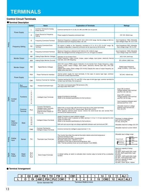
TERMINALS<br />
Control Circuit Terminals<br />
Terminal Description<br />
Symbol Name Explanation of Terminals Ratings<br />
Power Supply<br />
L<br />
H<br />
Common Terminal for Analog<br />
Power Source<br />
Power Source for Frequency<br />
Setting<br />
Common terminal for H, O, O2, OI, AM, and AMI. Do not ground. -<br />
Power supply for frequency command input<br />
DC 10V, 20mA max.<br />
O<br />
Frequency Command Terminal<br />
Maximum frequency is attained at DC 10V in DC 0-10V range. Set the voltage at A014 to<br />
command maximum frequency below DC 10V.<br />
Input impedance: 10kΩ, Allowable<br />
input voltage range: DC -0.3-+12V<br />
Analog<br />
Frequency Setting<br />
O2<br />
Frequency Command Extra<br />
Terminal<br />
O2 signal is added to the frequency command of O or OI in DC 0-±10V range. By<br />
changing configuration, frequency command can be input also at O2 terminal.<br />
Input impedance:10kΩ, Allowable<br />
input voltage range: DC 0-±12V<br />
OI<br />
Frequency Command Terminal<br />
Maximum frequency is attained at DC 20mA in DC 4-20mA range.<br />
When the intelligent terminal configured as AT is on, OI signal is enabled.<br />
Input impedance: 100Ω, Allowable<br />
input voltage range: DC 0-24mA<br />
Monitor Output<br />
AM<br />
AMI<br />
Analog Output Monitor (Voltage)<br />
Analog Output Monitor (Current)<br />
Selection of one function from:<br />
Output frequency, output current, torque, output voltage, input power, electronic thermal<br />
load ratio, and LAD frequency.<br />
DC 0-10V, 2mA max.<br />
DC 4-20mA, 250Ω max.<br />
Monitor Output<br />
FM<br />
Digital Monitor (Voltage)<br />
[DC0-10V output (PWM output)] Selection of one function from: Output frequency, output<br />
current, torque, output voltage, input power, electronic thermal load ratio, and LAD<br />
frequency.<br />
[Digital pulse output (Pulse voltage DC 0/10V)] Outputs the value of output frequency as<br />
digital pulse (duty 50%)<br />
Digital output frequency<br />
range: 0-3.6kHz, 1.2mA max.<br />
Power Supply<br />
P24<br />
CM1<br />
Power Terminal for Interface<br />
Common Terminal for Interface<br />
Internal power supply for input terminals. In the case of source type logic, common<br />
terminal for contact input terminals.<br />
Common terminal for P24, TH, and FM. In the case of sink type logic, common terminal for<br />
contact input terminals. Do not ground.<br />
DC 24V, 100mA max.<br />
-<br />
Digital<br />
Contact<br />
Input<br />
Run<br />
Command<br />
Functions<br />
FW<br />
1<br />
2<br />
3<br />
4<br />
5<br />
6<br />
7<br />
8<br />
Forward Command Input<br />
Intelligent Input Terminals<br />
The motor runs forward when FW terminal is ON,<br />
and stops when FW is OFF.<br />
Assign 8 functions to terminals.<br />
(Refer to the standard specifications for the functions.)<br />
[Input ON condition]<br />
Voltage between each terminal<br />
and PLC: DC 18V min.<br />
[Input OFF condition]<br />
Voltage between each terminal<br />
and PLC: DC 3V max.<br />
Input impedance between each<br />
terminal and PLC: 4.7Ω<br />
Common<br />
Terminal<br />
PLC<br />
Common Terminal for<br />
Intelligent Input Terminals,<br />
Common Terminal for<br />
External Power Supply for<br />
PLCs, etc.<br />
Select sink or source logic with the short-circuit bar on the control terminals.<br />
Sink logic: Short P24 to PLC / Source logic: Short CM1 to PLC.<br />
When applying external power source, remove the short-circuit bar and connect PLC<br />
terminal to the external device.<br />
Allowable maximum voltage<br />
between each terminal and<br />
PLC: DC 27V<br />
Open<br />
Collector<br />
Output<br />
State<br />
11<br />
12<br />
13<br />
14<br />
15<br />
Intelligent Output Terminals<br />
Assign 5 functions to open collector outputs.<br />
When the alarm code is selected at C062, terminal 11-13 or 11-14 are reserved for error<br />
codes of inverter trip.<br />
(Refer to the standard specifications for the functions.)<br />
Both sink and source logic are always applicable between each terminal and CM1.<br />
Decrease in voltage between<br />
each terminal and CM2:<br />
4V max. during ON<br />
Allowable maximum voltage: DC 27V<br />
CM2<br />
Common Terminal for<br />
Intelligent Output Terminals<br />
Common terminal for intelligent output terminal 11-15.<br />
Allowable maximum current: 50mA<br />
Analog<br />
Analog<br />
Input<br />
Sensor<br />
TH<br />
Thermistor Input Terminals<br />
The inverter trips when the external thermistor detects abnormal temperature.<br />
Common terminal is CM1.<br />
[Recommended thermistor characteristics]<br />
Allowable rated power: 100mW or over.<br />
Impedance in the case of abnormal temperature: 3kΩ<br />
Note: Thermal protection level can be set between 0 and 9999Ω.<br />
Allowable input voltage range<br />
[Input Circuit]<br />
TH<br />
Thermistor<br />
CM1<br />
DC0-8V<br />
DC8V<br />
10kΩ<br />
1kΩ<br />
Digital<br />
Relay<br />
Output<br />
State/<br />
Alarm<br />
AL0<br />
AL1<br />
AL2<br />
Alarm Output Terminals<br />
In default setting, an alarm is activated when inverter output is turned off by a protective<br />
function.<br />
Maximum capacity of relays<br />
AL1-AL0:<br />
AC 250V, 2A(R load)/0.2A(L load)<br />
DC 30V, 8A(R load)/0.6A(L load)<br />
AL2-AL0:<br />
AC 250V, 1A(R load)/0.2A(L load)<br />
DC 30V, 1A(R load)/0.2A(L load)<br />
Minimum capacity of relays<br />
AL1-AL0, AL2-AL0:<br />
AC100V, 10mA DC5V, 100mA<br />
Terminal Arrangement<br />
L<br />
H<br />
O<br />
O2 AM FM TH FW 8<br />
OI AM1 P24 PLC CM1<br />
Screw diameter:M3<br />
CM1 5 3<br />
7 6 4 2<br />
Terminal Width:6.4mm<br />
1<br />
14 13 11 AL1<br />
15 CM2 12 AL0 AL2<br />
13