
Create successful ePaper yourself
Turn your PDF publications into a flip-book with our unique Google optimized e-Paper software.
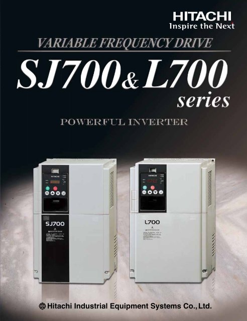
<strong>SJ700</strong> <strong>L700</strong> &<br />
Powerful Inverter<br />
series<br />
Hitachi Industrial Equipment Systems Co.,Ltd.
High performance, powerful<br />
High starting Torque,<br />
Powerful Drive and easy setting<br />
High starting Torque<br />
Improved Sensorless Vector Control and Auto Tuning<br />
produce high starting torque of 200% or more at 0.3Hz.* 1<br />
Easy setup of motor constants<br />
Ideal for applications which need high torque, such as<br />
cranes, extruders and lifts.<br />
Motor Torque vs. Speed<br />
Trip avoidance function<br />
Over current &<br />
voltage suppress function<br />
Higher internal calculation speed improves current control<br />
performance.<br />
Over-current suppress and Over-voltage suppress functions<br />
avoid inverter trip during acceleration and deceleration.<br />
Torque [%]<br />
200<br />
0.3Hz<br />
100<br />
0<br />
-100<br />
-200<br />
300 600 900 1200 1500 1800<br />
Frequency<br />
Motor current<br />
OC-Trip<br />
Speed (min -1 )<br />
*1Starting torque<br />
<strong>Series</strong> Applicable motor<br />
0.4 to 55kW<br />
<strong>SJ700</strong><br />
75 to 132kW<br />
185 to 400kW<br />
11 to 75kW<br />
<strong>L700</strong><br />
90 to 160kW<br />
Starting torque<br />
0.3Hz/200%<br />
0.3Hz/180%<br />
0.3Hz/150%<br />
0.5Hz/150%<br />
0.5Hz/120%<br />
Over-current suppress OFF<br />
Hitachi exclusive<br />
0Hz Domain sensorless<br />
vector control<br />
Develops 150% * 2 torque at 0Hz speed<br />
reference<br />
Ideal for cranes and other applications<br />
that require high torque at starting.<br />
* 2 when inverter is one frame size larger than motor.<br />
Position Control Function<br />
The <strong>SJ700</strong>, with optional feedback board installed, together<br />
with an encoder-equipped motor can perform position<br />
control.<br />
For many applications, suitable performance can be<br />
achieved at a lower cost than servo systems.<br />
Based on your four motion parameters (position command,<br />
speed command, acceleration time and deceleration time),<br />
the <strong>SJ700</strong> will move an object from original position A to<br />
target position B. After the movement, the inverter keeps<br />
servo lock status.<br />
Target point B<br />
Starting point A<br />
Impact load<br />
Suppresses over current and continues running<br />
Over-current suppress ON<br />
DC Bus AVR Function<br />
During Deceleration<br />
The <strong>SJ700</strong> controls deceleration time so that the DC bus<br />
voltage does not exceed the over-voltage trip level, providing<br />
trip-less operation during deceleration.<br />
Motor current<br />
Voltage of the<br />
main circuit DC<br />
Output frequency<br />
1
functions, yet user friendly.<br />
&<br />
Programming [EzSQ: Easy Sequence] function<br />
*<br />
=<strong>SJ700</strong> <strong>Series</strong><br />
=<strong>L700</strong> <strong>Series</strong><br />
Inverter control by Built-in<br />
Programming function<br />
Sequence operation is realized by downloading to an inverter a<br />
program created with Hitachi's Pro Drive Next software.<br />
Tailor inverter operation to meet changing process<br />
requirements, and replace separate PLCs in some cases.<br />
By simplifying or eliminating external hardware, signficant cost<br />
savings can be achieved.<br />
Password function is incorporated to provide security for<br />
proprietary program data against loss or unauthorized<br />
modification.<br />
Typical Example - Replacing External Relay Circuit<br />
Standard Inverter<br />
<br />
<br />
<br />
<br />
<br />
<br />
<br />
<br />
<br />
<br />
<br />
<br />
<br />
<br />
<br />
<br />
<br />
<br />
<br />
<br />
<br />
EzSQ<br />
Programming<br />
<br />
<br />
<strong>SJ700</strong> Using EzSQ<br />
Programming Window<br />
Download<br />
<br />
<br />
<br />
Language Spec<br />
I/O function<br />
Reserved word<br />
Item<br />
Language type<br />
BASIC Like<br />
Description<br />
Supported Device Windows(DOS/V)OS:Windows2000, WindowsXP)<br />
1,024 steps or 6k byte<br />
Memory area<br />
(Smaller of these)Program is stored in internal of inverter.<br />
Editor(Windows), Display(Windows)<br />
Programming<br />
Grammar check(Windows)<br />
environment<br />
Program download/upload, All clear<br />
Executable format Interpreter 2.0ms/command (Sub routine supported. 8 nested)<br />
Contact signal/Open collector signal input<br />
(Internal DC24V power supply available)<br />
External input<br />
External output<br />
Command<br />
Variable<br />
External digital<br />
contact input<br />
External analog<br />
input<br />
General-purpose<br />
output terminal<br />
External analog<br />
output<br />
Program RUN<br />
FW terminal is reserved<br />
command<br />
General-purpose<br />
Maximum of 8 point(X(00)-X(07))<br />
input<br />
XA(0) : 0-10V (O terminal)<br />
XA(1) : 4-20mA (OI terminal)<br />
XA(2) : 0-10V (O2 terminal)<br />
Maximum of 8 point(Y(00)-Y(05))<br />
YA(0) : Setup for FM terminal is possible.<br />
YA(1) : Setup for AM terminal is possible.<br />
YA(2) : Setup for AMI terminal is possible.<br />
Programmable flow control <br />
Operation command <br />
I/O control(Bit input, Word input, Bit output, Word output)<br />
Timer control <br />
Inverter parameter setting<br />
User<br />
U(00)-U(31)/32 point<br />
Timer<br />
UL(00)-UL(07)/8 point<br />
Set frequency SET-Freq<br />
Acceleration time ACCEL<br />
Deceleration time DECEL<br />
Output frequency, Output current, Rotative direction,<br />
PID feedback, Converted frequency, Output torque,<br />
Monitor<br />
Output voltage, Power, Cumulative RUN time,<br />
Cumulative power-on time, trip<br />
General-purpose<br />
X(00)-X(07)/8 point<br />
input contact<br />
General-purpose<br />
Y(00)-Y(05)/6 point(1 point is relay output)<br />
output contact<br />
Internal user UB(00)-UB(07)/8 point<br />
Internal timer<br />
TD(0)-TD(7)/8 point<br />
contact<br />
Inverter input<br />
In a remote operator display code.<br />
and output<br />
* Windows® is a registered trademark of Microsoft Corporation.U.S.A and other countries.<br />
EMC Filter & Brake circuit integrated as Standard<br />
Built-in EMC Filter up to 150kW *<br />
Cost and space reduction compared with external EMC Filter.<br />
Reduces electromagnetic noise.<br />
Meets EN61800-3 2nd-Environment<br />
<strong>SJ700</strong>: European Version and Japanese Version does not have 150 kW<br />
* <strong>L700</strong>: All models<br />
Brake circuit up to 22kW *<br />
Cost and Space reduction compared with external Braking<br />
Controller.<br />
<strong>L700</strong>: Up to 30kW<br />
*<br />
Level [db]<br />
130<br />
120<br />
110<br />
100<br />
90<br />
80<br />
70<br />
60<br />
50<br />
40<br />
30<br />
20<br />
10<br />
Example (<strong>SJ700</strong>-110HFEF2)<br />
EN61800-3 2nd Envinment<br />
[C3]QP Limit Level<br />
0<br />
150k 200k 500k 1M 2M 5M 7M 10M 20M 30M<br />
Frequency [Hz]<br />
QP: Quasi Peak<br />
2
Ease of Maintenance<br />
Easy-removable construction<br />
for maintenance<br />
Field replacement of cooling fan(s) and DC bus capacitors<br />
can be accomplished in a fraction of the time.<br />
Using Logic terminal move to <strong>SJ700</strong> without wiring change.<br />
Read SJ300 Parameter by WOP remote operator and write<br />
them in to <strong>SJ700</strong><br />
Easy Operation<br />
User selection of Displayed<br />
Parameters<br />
Data comparison function<br />
Allows display of only parameters changed from default.<br />
User selected function<br />
Display of up to 12 User Defined Parameters U001 to U012.<br />
Basic mode (default)<br />
Basic display mode for commonly used parameters.<br />
Easy-removable<br />
Cooling Fan<br />
SJ300series<br />
Parameter<br />
read write<br />
Easy-removable<br />
DC bus Capacitors<br />
(<strong>SJ700</strong>: above 15kW<br />
<strong>L700</strong>: above 18.5kW)<br />
<strong>SJ700</strong>series<br />
Chose Basic<br />
Parameter<br />
Basic<br />
mode<br />
Indication only<br />
Basic Parameter<br />
Removable Control circuit terminals<br />
(Move to <strong>SJ700</strong> without rewiring)<br />
Other Functions<br />
-The direct input of function code selection is possible rather<br />
than scrolling through the list.<br />
-Holding down the function key for 3 seconds, causes the<br />
display to jump to output frequency monitor (d001) mode<br />
from any menu location.<br />
*1Control circuit terminals comparison table<br />
<strong>Series</strong><br />
Input terminals<br />
<strong>SJ700</strong><br />
9terminals<br />
<strong>L700</strong><br />
(Intelligent 8terminals,FW)<br />
SJ300<br />
L300P<br />
6terminals<br />
(Intelligent 5terminals,FW)<br />
Output terminals<br />
5terminals<br />
(Open collector outputs)<br />
2terminals<br />
(Relay outputs)<br />
Long life time components &<br />
Life time warning function<br />
Long life time components<br />
Design lifetime 10 Years or more for DC bus capacitors &<br />
Cooling Fan.<br />
Cooling Fan ON/OFF control function for longer fan life.<br />
*Ambient temperature: Average 40 deg C (<strong>L700</strong>: 30 deg C)<br />
(no corrosive gases, oil mist or dust)<br />
Design lifetime is calculated, and not guaranteed.<br />
Network compatibility<br />
A serial RS-485 Modbus-RTU port is standard.<br />
The <strong>SJ700</strong> can communicate with DeviceNet,<br />
PROFIBUS-DP, and other networks with communication<br />
options.<br />
-DeviceNet is a trade mark of Open DeviceNet Vender Association, Inc.<br />
-PROFIBUS-DP is a registered trade mark of PROFIBUS Nutzer<br />
Organization<br />
Simple & Low cost wiring, Ease of installation and replacement<br />
Life time warning function<br />
Perform preventive maintenance before a failure occurs<br />
using the Lifetime Warning function.<br />
DC bus capacitor, cooling fan, heat sink temperature and<br />
motor temperature can be monitored in order to replace<br />
components prior to failure.<br />
3
&<br />
Global standards<br />
Conformity to global standards<br />
CE, UL, c-UL, C-Tick approvals.<br />
Logic input & output Terminal<br />
apply sink & source logic<br />
Wide Input power voltage range<br />
Input voltage 240V for 200V class and 480V<br />
for 400V class as standard.<br />
Environmental Friendliness<br />
Micro Surge Voltage suppress<br />
function<br />
Hitachi original PWM control method limits motor terminal<br />
voltage to less than two of inverter DC bus voltage.<br />
Lower than Hitachi motor Max. insulation voltage (1,250V)<br />
(During regeneration, the motor terminal voltage may exceed the motor<br />
maximum insulation voltage(1,250V))<br />
Motor terminal voltage<br />
1,250V<br />
E=650V, cable=100m<br />
EU RoHS compliant<br />
EU RoHS compliant<br />
(except solder in power module)<br />
Improvement of environment<br />
Varnish coating of internal PC board & plating of main circuit<br />
copper bus bar are standard.<br />
Versatile Functions<br />
Instantaneous Power Failure<br />
Disregard Function<br />
The <strong>SJ700</strong> ignores instantaneous power failure when power<br />
fluctuation happens frequently, as long as DC bus voltage<br />
remains higher than under-voltage trip level.<br />
Emergency stop<br />
Shuts down the inverter by hardware, bypassing<br />
the CPU, to achieve a reliable, emergency stop function.<br />
Intelligent input terminal and output<br />
terminal ON/OFF delay function<br />
Helps simplify external circuits.<br />
Active frequency matching function<br />
Motor frequency match restart function operates<br />
effectively even without motor residual voltage.<br />
Controlled deceleration and stop<br />
on power loss<br />
Analog Input Disconnection<br />
Detection Function<br />
The <strong>SJ700</strong> (<strong>L700</strong>) outputs a disconnection signal when<br />
frequency command through analog input is lost.<br />
Acceleration/Deceleration curve<br />
functions<br />
The curve shape (five kinds, such as S-curve, etc.) can be<br />
chosen according to the application requirements.<br />
Analog Command Holding<br />
Function (AHD)<br />
Output frequency can be changed with UP/DOWN Function,<br />
or with an analog signal as reference value. The set<br />
frequency at power shutdown can be saved, too.<br />
Pulse train input function<br />
Pulse train input for Frequency reference or PID<br />
feed back signal, with SJ-FB (speed feed back card option).<br />
Integrated Input Electric Power<br />
monitor<br />
Input electric power (kW) and Integrated input electric<br />
power for monitoring energy saving.<br />
Automatic Carrier Frequency<br />
Adjustment Function<br />
The <strong>SJ700</strong> detects motor current and automatically reduces<br />
carrier frequency according to the current.<br />
The resolution of analog outputs<br />
(voltage, current) is improved to 10 bits.<br />
4
STANDARD SPECIFICATIONS<br />
<strong>SJ700</strong> <strong>Series</strong><br />
3-phase 200V class<br />
Model <strong>SJ700</strong>-<br />
Enclosure (*1)<br />
Applicable motor (4-pole, kW(HP)) (*2)<br />
Rated capacity 200V<br />
(kVA)<br />
240V<br />
Output Ratings<br />
Input Rating<br />
Braking<br />
Vibration (*5)<br />
EMC filter<br />
Zero-phase Reactor<br />
Weight(lbs.)<br />
US Version<br />
JP Version<br />
Rated output current (A)<br />
Overload capacity(output current)<br />
Rated output voltage (*3)<br />
Rated input voltage (V)<br />
Rated input current (A)<br />
Dynamic braking (Short-time) (*4)<br />
Minimum value of resistor (Ω)<br />
3-phase 400V class<br />
Model <strong>SJ700</strong>-<br />
Enclosure (*1)<br />
Applicable motor (4-pole, kW(HP)) (*2)<br />
Rated capacity 400V<br />
(kVA)<br />
480V<br />
Output Ratings<br />
Input Rating<br />
Braking<br />
Vibration (*5)<br />
EMC filter<br />
Zero-phase Reactor<br />
Weight(lbs.)<br />
European Version<br />
US Version<br />
JP Version<br />
Rated output current (A)<br />
Overload capacity(output current)<br />
Rated output voltage (*3)<br />
Rated input voltage (V)<br />
Rated input current (A)<br />
Dynamic braking (Short-time) (*4)<br />
Minimum value of resistor (Ω)<br />
004LFUF2 007LFUF2 015LFUF2 022LFUF2 037LFUF2 055LFUF2 075LFUF2 110LFUF2 150LFUF2 185LFUF2 220LFUF2 300LFUF2 370LFUF2 450LFUF2 550LFUF2<br />
004LFF2 007LFF2 015LFF2 022LFF2 037LFF2 055LFF2 075LFF2 110LFF2 150LFF2 185LFF2 220LFF2 300LFF2 370LFF2 450LFF2 550LFF2<br />
0.4(1/2) 0.75(1)<br />
1.0 1.7<br />
1.2 2.0<br />
3 5<br />
3.3<br />
50<br />
IP20<br />
150%,60sec., 200%,3sec.<br />
3-phase (3-wire) 200 to 240V (corresponding to input voltage)<br />
3-phase 200 to 240V+10%, -15%, 50/60Hz±5%<br />
12 18 26 35 51 70 84<br />
Built-in BRD circuit (optional resistor)<br />
Built-in (EN61800-3 category C3)<br />
Built-in<br />
3-phase (3-wire) 380 to 480V (corresponding to input voltage)<br />
3-phase 380 to 480V +10%, -15%, 50/60Hz±5%<br />
Built-in (EN61800-3 category C3)<br />
Built-in<br />
55(75)<br />
76.2<br />
91.4<br />
220<br />
133 160 200 242<br />
External dynamic braking unit (option)<br />
-<br />
2.9m/s 2 (0.3G), 10-55Hz<br />
30(66) 43(94.6)<br />
007HFEF2 015HFEF2 022HFEF2 040HFEF2 055HFEF2 075HFEF2 110HFEF2 150HFEF2 185HFEF2 220HFEF2 300HFEF2 370HFEF2 450HFEF2 550HFEF2<br />
007HFUF2 015HFUF2 022HFUF2 040HFUF2 055HFUF2 075HFUF2 110HFUF2 150HFUF2 185HFUF2 220HFUF2 300HFUF2 370HFUF2 450HFUF2 550HFUF2<br />
007HFF2 015HFF2 022HFF2 037HFF2 055HFF2 075HFF2 110HFF2 150HFF2 185HFF2 220HFF2 300HFF2 370HFF2 450HFF2 550HFF2<br />
IP20<br />
0.75(1) 1.5(2) 2.2(3)<br />
3.7(5)<br />
4.0(5) 5.5(7.5) 7.5(10) 11(15) 15(20) 18.5(25) 22(30) 30(40) 37(50) 45(60) 55(75)<br />
1.7 2.6 3.6 6.2 9.6 13.1 17.3 22.1 26.3 33.2 40.1 51.9 63.0 77.6<br />
2.0 3.1 4.4 7.4 11.6 15.7 20.7 26.6 31.5 39.9 48.2 62.3 75.6 93.1<br />
2.5 3.8 5.3 9.0 14 19 25 32 38 48 58 75 91 112<br />
150%,60sec., 200%,3sec.<br />
2.8<br />
100<br />
3.5(7.7)<br />
5.5<br />
50<br />
4.2<br />
100<br />
3.5(7.7)<br />
1.5(2)<br />
2.5<br />
3.1<br />
7.5<br />
8.3<br />
35<br />
5.8<br />
100<br />
3.5(7.7)<br />
2.2(3)<br />
3.6<br />
4.3<br />
10.5<br />
35<br />
9.9<br />
70<br />
3.5(7.7)<br />
3.7(5)<br />
5.7<br />
6.8<br />
16.5<br />
35<br />
3.5(7.7) 3.5(7.7) 3.5(7.7) 3.5(7.7) 3.5(7.7)<br />
17<br />
70<br />
6(13.2)<br />
5.5(7.5) 7.5(10)<br />
8.3<br />
9.9<br />
24<br />
16<br />
23<br />
35<br />
6(13.2)<br />
11.0<br />
13.3<br />
32<br />
10<br />
5.9m/s 2 (0.6G), 10-55Hz<br />
30<br />
35<br />
11(15)<br />
15.9<br />
19.1<br />
46<br />
10<br />
15(20)<br />
22.1<br />
26.6<br />
64<br />
18.5(25)<br />
26.3<br />
31.5<br />
76<br />
22(30)<br />
32.9<br />
39.4<br />
95<br />
35<br />
24<br />
7.5<br />
42<br />
24<br />
7.5<br />
6(13.2) 14(30.8) 14(30.8) 14(30.8) 22(48.4) 30(66)<br />
53<br />
20<br />
105<br />
5<br />
30(40)<br />
41.9<br />
50.2<br />
121<br />
37(50)<br />
50.2<br />
60.2<br />
145<br />
6(13.2) 6(13.2) 6(13.2) 14(30.8) 14(30.8) 14(30.8) 22(48.4) 30(66)<br />
Built-in BRD circuit (optional resistor)<br />
5.9m/s 2 (0.6G), 10-55Hz<br />
45(60)<br />
63.0<br />
75.6<br />
182<br />
64 83 100 123<br />
External dynamic braking unit (option)<br />
-<br />
2.9m/s 2 (0.3G), 10-55Hz<br />
30(66)<br />
30(66)<br />
Model <strong>SJ700</strong>-<br />
Enclosure (*1)<br />
Applicable motor (4-pole, kW(HP)) (*2)<br />
Rated capacity 400V<br />
(kVA)<br />
480V<br />
Output Ratings<br />
Input Rating<br />
Braking<br />
Vibration (*5)<br />
EMC filter<br />
Zero-phase Reactor<br />
Weight(lbs.)<br />
European Version<br />
US Version<br />
JP Version<br />
Rated output current (A)<br />
Overload capacity(output current)<br />
Rated output voltage (*3)<br />
Rated input voltage (V)<br />
Rated input current (A)<br />
Dynamic braking (Short-time) (*4)<br />
Minimum value of resistor (Ω)<br />
750HFEF2 900HFEF2 1100HFEF2 1320HFEF2 1850HFE2 2200HFE2 3150HFE2 4000HFE2<br />
750HFUF2 900HFUF2 1100HFUF2 1500HFUF2 1850HFU2 2200HFU2 3150HFU2 4000HFU2<br />
750HFF2 900HFF2 1100HFF2 1320HFF2 1850HF2 2200HF2 3150HF2 4000HF2<br />
IP00<br />
75(100) 90(125) 110(150) 132(175) 185(250) 220(300) 315(400) 400(550)<br />
103.2<br />
123.8<br />
149<br />
121.9<br />
146.3<br />
176<br />
150.3<br />
180.4<br />
217<br />
180.1<br />
216.1<br />
260<br />
256<br />
308<br />
370<br />
305<br />
366<br />
440<br />
416<br />
499<br />
600<br />
554<br />
665<br />
800<br />
150%,60sec., 200%,0.5sec. 150%,60sec., 180%,0.5sec.<br />
3-phase (3-wire) 380 to 480V (corresponding to input voltage)<br />
3-phase 380 to 480V +10%, -15%, 50/60Hz±5%<br />
164 194 239 286 389 455 630 840<br />
External dynamic braking unit (option)<br />
-<br />
2.9m/s 2 (0.3G), 10-55Hz<br />
1.96m/s 2 (0.2G), 10-55Hz<br />
Built-in (EN61800-3 category C3)<br />
External Option<br />
Built-in<br />
External Option<br />
60(132) 60(132) 80(176) 80(176) 140(308) 145(319) 210(462) 360(792)<br />
(note) You need to use DC-Reactor(DCL-H-400) for<br />
<strong>SJ700</strong>-4000HF(E,U)2 inverter.<br />
5
STANDARD SPECIFICATIONS<br />
<strong>L700</strong> <strong>Series</strong><br />
3-phase 200V class<br />
Model <strong>L700</strong>-<br />
Enclosure (*1)<br />
Applicable motor (4-pole, kW(HP)) (*2)<br />
Output Ratings<br />
Input Rating<br />
Braking<br />
Vibration (*5)<br />
EMC filter<br />
Zero-phase Reactor<br />
Weight(lbs.)<br />
Rated capacity 200V<br />
(kVA)<br />
240V<br />
Rated output current (A)<br />
Overload capacity(output current)<br />
Rated output voltage (*3)<br />
Rated input voltage (V)<br />
Rated input current (A)<br />
Dynamic braking (Short-time) (*4)<br />
Minimum value of resistor (Ω)<br />
110LFF 150LFF 185LFF 220LFF 300LFF 370LFF 450LFF 550LFF 750LFF<br />
IP20<br />
11(15)<br />
15.2<br />
18.2<br />
44<br />
15(20)<br />
20.0<br />
24.1<br />
58<br />
18.5(25)<br />
25.2<br />
30.3<br />
73<br />
22(30)<br />
29.4<br />
35.3<br />
85<br />
30(40)<br />
39.1<br />
46.9<br />
113<br />
37(50)<br />
48.4<br />
58.1<br />
140<br />
45(60)<br />
58.5<br />
70.2<br />
169<br />
55(75)<br />
72.7<br />
87.2<br />
210<br />
120%,60sec<br />
75(100)<br />
93.5<br />
112.2<br />
270<br />
3-phase (3-wire) 200 to 240V (corresponding to input voltage)<br />
3-phase 200 to 240V+10%, -15%, 50/60Hz±5%<br />
48 64 80 94 120 150 186 240 280<br />
Built-in BRD circuit (optional resistor) External dynamic braking unit (option)<br />
10 10 7.5 7.5 5<br />
-<br />
5.9m/s 2 (0.6G), 10-55Hz<br />
2.9m/s 2 (0.3G), 10-55Hz<br />
Built-in (EN61800-3 category C3)<br />
Built-in<br />
6(13.2) 6(13.2) 14(30.8) 14(30.8) 14(30.8) 22(48.4) 30(66) 30(66) 43(94.6)<br />
3-phase 400V class<br />
Model <strong>L700</strong>-<br />
110HFF<br />
150HFF<br />
185HFF<br />
220HFF<br />
Enclosure (*1) IP20 IP00<br />
Applicable motor (4-pole, kW(HP)) (*2)<br />
Rated capacity<br />
(kVA)<br />
400V<br />
480V<br />
11(15)<br />
15.2<br />
18.2<br />
15(20)<br />
20.0<br />
24.1<br />
18.5(25)<br />
25.6<br />
30.7<br />
22(30)<br />
29.7<br />
35.7<br />
30(40)<br />
39.4<br />
47.3<br />
37(50)<br />
48.4<br />
58.1<br />
45(60)<br />
58.8<br />
70.6<br />
55(75)<br />
72.7<br />
87.2<br />
75(100)<br />
93.5<br />
112.2<br />
90(125)<br />
110.8<br />
133.0<br />
110(150)<br />
135.0<br />
162.1<br />
132(150)<br />
159.3<br />
191.2<br />
160(220)<br />
200.9<br />
241.1<br />
Output Ratings Rated output current (A)<br />
22 29 37 43 57 70 85 105 135 160 195 230 290<br />
Overload capacity(output current)<br />
120%,60sec<br />
Rated output voltage (*3)<br />
3-phase (3-wire) 380 to 480V (corresponding to input voltage)<br />
Input Rating<br />
Rated input voltage (V)<br />
3-phase 380 to 480V +10%, -15%, 50/60Hz±5%<br />
Rated input current (A)<br />
24 32 41 47 63 77 94 116 149 176 199 253 300<br />
Braking<br />
Dynamic braking (Short-time) (*4) Built-in BRD circuit (optional resistor)<br />
External dynamic braking unit (option)<br />
Minimum value of resistor (Ω) 35 35 24 24 20<br />
-<br />
Vibration (*5)<br />
5.9m/s 2 (0.6G), 10-55Hz<br />
2.9m/s 2 (0.3G), 10-55Hz<br />
EMC filter<br />
Built-in (EN61800-3 category C3)<br />
Zero-phase Reactor<br />
Built-in<br />
Weight(lbs.)<br />
6(13.2) 6(13.2) 14(30.8) 14(30.8) 14(30.8) 22(48.4) 30(66) 30(66) 30(66) 55(121) 55(121) 70(154) 70(154)<br />
*1: The protection method conforms to JIS C 0920(IEC60529).<br />
*2: The applicable motor refers to Hitachi standard 3-phase motor (4-pole).To use other motors, be sure to prevent the rated motor current (50Hz) from exceeding the rated output current of the inverter.<br />
*3: The output voltage decreases as the main power supply voltage decreases except for the use of AVR function.<br />
*4: Braking resistor is not integrated in the inverter. Please install optional braking resistor or dynamic braking unit when large braking torque is required.<br />
*5: Conforms to the test method specified in JIS C 60068-2-62010 IEC 60068-2-6 2007).<br />
*6: To operate the motor beyond 50/60Hz, please consult with the motor manufacturer about the maximum allowable rotation speed.<br />
*7: Storage temperature refers to the temperature in transportation.<br />
*8: The frequency command is the maximum frequency at 9.8V for input voltage 0 to 10VDC, or at 19.6mA for input current 4 to 20mA.If this characteristic is not satisfactory for your application,contact your Hitachi representative.<br />
300HFF<br />
370HFF<br />
450HFF<br />
550HFF<br />
750HFF<br />
900HFF<br />
1100HFF 1320HFF 1600HFF<br />
Model Name Indication<br />
Model Configuration<br />
Applicable Motor kW (HP)<br />
LFUF2<br />
3-phase 200V<br />
LFF2<br />
<strong>SJ700</strong><br />
HFEF2<br />
3-phase 400V HFUF2<br />
Available<br />
0.4<br />
(1/2)<br />
<strong>SJ700</strong> series<br />
<strong>Series</strong> Name<br />
Applicable Motor Capacity<br />
0.75<br />
(1)<br />
1.5<br />
(2)<br />
Power Source<br />
2.2<br />
(3)<br />
3.7<br />
(5)<br />
<br />
004: 0.4kW(1/2HP)<br />
|<br />
4000:400kW(500HP)<br />
L: 3-phase 200V class<br />
H: 3-phase 400V class<br />
F: With keypad<br />
U : US version<br />
E : European version<br />
Note: Japanese version<br />
F: Integrated EMC filter<br />
Version<br />
4.0<br />
(5)<br />
5.5<br />
(7.5)<br />
7.5<br />
(7.5)<br />
11<br />
(15)<br />
15<br />
(20)<br />
18.5<br />
(25)<br />
22<br />
(30)<br />
30<br />
(40)<br />
37<br />
(50)<br />
<strong>L700</strong> series<br />
<strong>Series</strong> Name<br />
Applicable Motor Capacity<br />
45<br />
(60)<br />
55<br />
(75)<br />
Power Source<br />
75<br />
(100)<br />
90<br />
(125)<br />
110<br />
(150)<br />
<br />
110: 11kW(15HP)<br />
|<br />
1600:160kW(220HP)<br />
L: 3-phase 200V class<br />
H: 3-phase 400V class<br />
F: With keypad<br />
F: Integrated EMC filter<br />
132<br />
(175)<br />
150<br />
(200)<br />
160<br />
(220)<br />
185<br />
(250)<br />
220<br />
(300)<br />
315<br />
(400)<br />
400<br />
(550)<br />
HFF2<br />
<strong>L700</strong><br />
3-phase 200V<br />
3-phase 400V<br />
LFF<br />
HFF<br />
6
SPECIFICATIONS<br />
General Specifications<br />
Control<br />
Input signal<br />
Items<br />
Control method<br />
Output frequency range (*6)<br />
Frequency accuracy<br />
Frequency resolution<br />
V/f characteristics<br />
Speed fluctuation<br />
Acceleration/deceleration time<br />
Starting Torque<br />
Carrier frequency range<br />
DC braking<br />
Operator<br />
Frequency<br />
External signal*8<br />
setting<br />
External port<br />
Operator<br />
Forward /reverse<br />
External signal<br />
Start /stop<br />
External port<br />
Terminals<br />
Intelligent<br />
input terminals<br />
Functions<br />
General Specifications<br />
Line to line sine wave pulse-width modulation (PWM) control<br />
0.1-400.0Hz(400kW:0.1-120Hz)<br />
Digital: ±0.01% of the maximum frequency, Analog: ±0.2%(25±10˚C)<br />
Digital setting: 0.01Hz, Analog setting: (Maximum frequency)/4,000 (O terminal: 12bit 0-10V, O2 terminal: 12bit -10-+10V)<br />
V/f optionally variable (30-400Hz of base frequency), V/f control (constant torque, reduced torque), Sensorless vector control, 0Hz domain sensorless vector<br />
control(*9), vector control (SJ-FB card option)(*9)<br />
±0.5% (sensorless vector control)<br />
0.01-3,600sec. (Linear/curve, accel./decel. selection), Two-stage accel./decel.<br />
<strong>SJ700</strong> (Sensorless vector control): 200% at 0.3Hz/ 75 to132kW :180% at 0.3Hz/185kW and over:150% at 0.3Hz<br />
<strong>L700</strong> (Sensorless vector control): 150% at 0.5Hz/ 90kW and over:120% at 0.3Hz,<br />
<strong>SJ700</strong> (0Hz domain with motor one frame size down):150% at around 0Hz/ 75kW and over: 130% at around 0Hz.<br />
<strong>SJ700</strong>: 0.5-15.0kHz(185kW and over:0.5-3.0kHz)/<strong>L700</strong>: 0.5-12.0kHz(90kW and over:0.5-8.0kHz)<br />
Performs at start: under set frequency at deceleration, via an external input (braking force, time, and operating frequency).<br />
Up and Down keys<br />
DC 0-10V, -10-+10V (input impedance 10kΩ), 4-20mA (input impedance 100Ω)<br />
Setting via RS485 communication<br />
Start/stop commands (forward/reverse switching by parameter setting)<br />
Forward-operation start/stop commands (reverse-operation start/stop possible when relevant commands are assigned to intelligent input terminals)3-wire<br />
input possible (when relevant commands are assigned to control circuit terminals)<br />
Setting via RS485 communication<br />
8 terminals, NO/NC switchable, sink logic/source logic switchable<br />
Reverse operation (RV), Multi-speed 1 setting (CF1), Multi-speed 2 setting (CF2), Multi-speed 3 setting (CF3), Multi-speed 4 setting (CF4), Jogging (JG),<br />
external DC braking (DB), 2nd motor control (SET), 2-stage acceleration/deceleration (2CH), free-run stop (FRS), external trip (EXT), unattended start<br />
protection (USP), commercial power supply switching (CS), software lock (SFT), analog input switching (AT), 3rd motor control (SET3), reset (RS), starting by<br />
3-wire input (STA), stopping by 3-wire input (STP), forward/reverse switching by 3-wire input (F/R), PID disable (PID), PID integration reset (PIDC), control<br />
gain switching (CAS), acceleration by remote control (UP), deceleration by remote control (DWN), data clearance by remote control (UDC), forcible operation<br />
(OPE), Multi-speed bit 1 (SF1), Multi-speed bit 2 (SF2), Multi-speed bit 3 (SF3), Multi-speed bit 4 (SF4), Multi-speed bit 5 (SF5), Multi-speed bit 6 (SF6),<br />
Multi-speed bit 7 (SF7), overload restriction selection (OLR), torque limit selection (enabling/disabling) (TL), torque limit 1 (TRQ1), torque limit 2 (TRQ2), P/PI<br />
switching (PPI), braking confirmation (BOK)(*9), orientation (ORT)(*9), LAD cancellation (LAC), clearance of position deviation (PCLR)(*9), permission of<br />
90˚shift phase (STAT)(*9), trigger for frequency addition (A145) (ADD), forcible-terminal operation (F-TM), permission of torque command input (ATR)(*9),<br />
cumulative power clearance (KHC), servo-on (SON)(*9), pre-excitation (FOC)(*9), general-purpose input 1 (MI1), general-purpose input 2 (MI2),<br />
general-purpose input 3 (MI3), general-purpose input 4 (MI4), general-purpose input 5 (MI5), general-purpose input 6 (MI6), general-purpose input 7 (MI7),<br />
general-purpose input 8 (MI8), analog command holding (AHD), Multistage position settings selection 1 (CP1)(*9), Multistage position settings selection 2<br />
(CP2)(*9), Multistage position settings selection 3 (CP3)(*9), Zero-return limit function (ORL)(*9), Zero-return trigger function (ORG)(*9), Forward drive stop (FOT)(*9),<br />
reverse drive stop (ROT)(*9), Speed / position switching (SPD)(*9), Pulse counter (PCNT), Pulse counter clear (PCC), Emergency stop (EMR) ,no assignment (no)<br />
Output signal<br />
Monitoring on display<br />
Other functions<br />
Protective functions<br />
Environmental<br />
conditions<br />
Options<br />
Thermistor input<br />
Intelligent<br />
output terminals<br />
Terminals<br />
Functions<br />
Ambient operating/storage<br />
temperature(*7)/ humidity<br />
Location<br />
Digital input expansion card<br />
Feedback expansion card<br />
Network interface card<br />
Others<br />
Monitor output<br />
terminals<br />
1 terminal (PTC characteristics)<br />
5 open-collector output terminals, NO/NC switchable, sink logic/source logic switchable 1 relay (1c-contact) output terminal: NO/NC switchable<br />
Running (RUN), constant-speed reached (FA1), set frequency overreached (FA2), overload notice advance signal (1) (OL), output deviation for PID control<br />
(OD), alarm signal (AL), set frequency reached (FA3), over-torque (OTQ), instantaneous power failure (IP), undervoltage (UV), torque limited (TRQ),<br />
operation time over (RNT), plug-in time over (ONT), thermal alarm signal (THM), brake release (BRK)(*9), braking error (BER)(*9), 0Hz detection signal<br />
(ZS), speed deviation maximum (DSE)(*9), positioning completed (POK)(*9), set frequency overreached 2 (FA4), set frequency reached 2 (FA5), overload<br />
notice advance signal (2) (OL2), PID feedback comparison (FBV), communication line disconnection (NDc), logical operation result 1 (LOG1), logical<br />
operation result 2 (LOG2), logical operation result 3 (LOG3), logical operation result 4 (LOG4), logical operation result 5 (LOG5), logical operation result 6<br />
(LOG6), capacitor life warning (WAC)(*12), cooling-fan speed drop (WAF), starting contact signal (FR), heat sink overheat warning (OHF), low-current<br />
indication signal (LOC), general-purpose output 1 (M01), general-purpose output 2 (M02), general-purpose output 3 (M03), general-purpose output 4<br />
(M04), general-purpose output 5 (M05), general-purpose output 6 (M06), inverter ready (IRDY), forward rotation (FWR), reverse rotation (RVR), major<br />
failure (MJA), window comparator O (WCO), window comparator OI (WCOI), window comparator O2 (WCO2), alarm code 0 to 3 (AC0 to AC3)<br />
Analog voltage output, analog current output, pulse-string output (e.g., A-F, D-F [n-fold, pulse output only], A, T, V, P)<br />
Output frequency, output current, output torque, frequency conversion data, trip history, input/output terminal status, electric power, and others<br />
Free V/f setting (7 breakpoints), frequency upper/lower limit, jump (center) frequency, acceleration/deceleration according to characteristic curve, manual<br />
torque boost level/breakpoint, energy-saving operation, analog meter adjustment, start frequency setting, carrier frequency adjustment, electronic thermal<br />
function (available also for free setting), external start/end frequency/frequency rate, analog input selection, retry after trip, restart after instantaneous power<br />
failure, output of various signals, starting with reduced voltage, overload restriction, initial-value setting, automatic deceleration at power failure, AVR<br />
function, fuzzy acceleration/deceleration(*9), online/offline auto-tuning, high-torque multi-motor operation(*12) (sensorless vector control of two motors by<br />
one inverter)<br />
Overcurrent protection, overvoltage protection, undervoltage protection, electronic thermal protection, temperature error protection, instantaneous power<br />
failure protection, phase loss input protection, braking-resistor overload protection, ground-fault current detection at power-on, USP error, external trip,<br />
emergency stop trip, CT error, communication error, option board error, and others<br />
-10-50˚C(*10) / -20-65˚C / 20-90%RH (No condensation)<br />
Altitude 1,000m or less, indoors (no corrosive gases or dust)<br />
SJ-DG (4digits BCD, 16bits binary)<br />
SJ-FB (vector control loop speed sensor)<br />
SJ-DN2(DeviceNet(TM)), SJ-PBT(PROFIBUS)<br />
EMI filters, input/output reactors, radio noize filters, braking resistors, braking units, LCR filter, communication cables<br />
*1: The protection method conforms to JIS C 0920(IEC60529).<br />
*2: The applicable motor refers to Hitachi standard 3-phase motor (4-pole).<br />
To use other motors, be sure to prevent the rated motor current (50Hz) from exceeding the rated output current of the inverter.<br />
*3: The output voltage decreases as the main power supply voltage decreases except for the use of AVR function.<br />
*4: Braking resistor is not integrated in the inverter. Please install optional braking resistor or dynamic braking unit when large braking torque is required.<br />
*5: Conforms to the test method specified in JIS C 60068-2-6:2010 (IEC 60068-2-6:2007).<br />
*6: To operate the motor beyond 50/60Hz, please consult with the motor manufacturer about the maximum allowable rotation speed.<br />
*7: Storage temperature refers to the temperature in transportation.<br />
*8: The frequency command is the maximum frequency at 9.8V for input voltage 0 to 10VDC,or at 19.6mA for input current 4 to 20mA.If this characteristic is not satisfactory for your application,contact your Hitachi representative.<br />
*9: <strong>L700</strong> series:The function is not provided.<br />
*10: <strong>L700</strong> series is -10 to 40℃.<br />
*11: Please be sure to connect DC reactor attached to 4000HF.<br />
*12: 1850HF,2200HF,3150HF and 4000HF :The function is not provided.<br />
7
DIMENSIONS<br />
<strong>SJ700</strong>-004037 LFUF2, LFF2<br />
<strong>SJ700</strong>-007040HFEF2, HFUF2, 007037HFF2<br />
<br />
<br />
<br />
<br />
<br />
<br />
<br />
<strong>SJ700</strong>-055110 LFUF2,LFF2 /HFEF2, HFUF2,HFF2<br />
<strong>L700</strong>-110150LFF/HFF<br />
<br />
<br />
<br />
<br />
<br />
<br />
<br />
<br />
<br />
<br />
<br />
<br />
<br />
<br />
<br />
<br />
<br />
<br />
<br />
<br />
<br />
<br />
<br />
<strong>SJ700</strong>-150220 LFUF2,LFF2 /HFEF2, HFUF2,HFF2<br />
<strong>L700</strong>-185300LFF/HFF<br />
<br />
<br />
<br />
<br />
<br />
<br />
<br />
<br />
<br />
<br />
<br />
<br />
<br />
<br />
<br />
<br />
<br />
<br />
<strong>SJ700</strong>-300 LFUF2,LFF2 /HFEF2, HFUF2, HFF2<br />
<strong>L700</strong>-370LFF/HFF<br />
<br />
<br />
<br />
<br />
<br />
<br />
<br />
<br />
<br />
<br />
<br />
<br />
<br />
<br />
<br />
<br />
<br />
<br />
<br />
<br />
<br />
<br />
<br />
<br />
<br />
<br />
<br />
<br />
<strong>SJ700</strong>-370450 LFUF2,LFF2<br />
<strong>SJ700</strong>-370550 HFEF2, HFUF2,HFF2<br />
<strong>L700</strong>-450550LFF/450750HFF<br />
<br />
<br />
<br />
<br />
<strong>SJ700</strong>-550 LFUF2,LFF2<br />
<strong>L700</strong>-750LFF<br />
<br />
<br />
<br />
<br />
<br />
<br />
<br />
<br />
<br />
<br />
<br />
<br />
<br />
<br />
<br />
<br />
<br />
<br />
<br />
<br />
<br />
<br />
<br />
<br />
<br />
<br />
<br />
<br />
[Unit : mm(inch)]<br />
Inches for reference only.<br />
* Please refer to page 26 for detailed information about compatibility with SJ300.<br />
8
DIMENSIONS<br />
<strong>SJ700</strong>-750, HFEF2, HFUF2, HFF2<br />
<strong>L700</strong>-, 1100HFF<br />
2-12(0.47)<br />
32.5 80<br />
(12.8) (3.15)<br />
Exhaust<br />
Digital Operator<br />
700(27.56)<br />
670(26.38)<br />
357(14.06) 79(3.11)<br />
<br />
2-12(0.47)<br />
300(11.81)<br />
390(15.35)<br />
Air intake<br />
<strong>SJ700</strong>-1100HFF2 <br />
<strong>L700</strong>-1320<br />
2-12(0.47)<br />
62.5 80<br />
(2.46) (3.15)<br />
Exhaust<br />
Digital Operator<br />
740(29.13)<br />
710(27.95)<br />
480(18.90) 79(3.11)<br />
2-12(0.47)<br />
380(14.96)<br />
480(18.90)<br />
Air intake<br />
270(10.63)<br />
270(10.63)<br />
<br />
[Unit : mm(inch)]<br />
Inches for reference only.<br />
9<br />
* Please refer to page 26 for detailed information about compatibility with SJ300.
DIMENSIONS<br />
<strong>SJ700</strong>-1850,2200HFEF2,HFUF2,HFF2<br />
3-15(0.59)<br />
2-M12 Eyebolts<br />
15(0.59)<br />
Exhaust<br />
Digital Operator<br />
965(37.99)<br />
995(39.17)<br />
<br />
15(0.59)<br />
15<br />
(0.59)<br />
57.5<br />
(22.63) 290(11.41) 290(11.41) 57.5(2.26)<br />
Air Intake<br />
370(14.56)<br />
695(27.36)<br />
4-M12 Screw Holes For Eyebolts<br />
<strong>SJ700</strong>-3150HFEF2,HFUF2,HFF2<br />
2-M12 Eyebolts<br />
3-15(0.59)<br />
15(0.59)<br />
2-M12 Screw Holes<br />
Exhaust<br />
Digital Operator<br />
Vent Holes B(*1)<br />
1270(50.0)<br />
1300(51.18)<br />
<br />
Vent Holes A(*1)<br />
15(0.59)<br />
15<br />
(0.59)<br />
50<br />
(1.96) 290(11.41) 290(11.41) 50(1.96)<br />
680(26.77)<br />
450(17.71)<br />
Air Intake<br />
4-M12 Screw Holes For Eyebolts<br />
*1 Vent-Holes A are formed on both right and left side.<br />
Vent-Holes B are just on right side.<br />
<strong>SJ700</strong>-4000HFEF2,HFUF2,HFF2<br />
Digital Oprator<br />
75(2.95)<br />
4-15(0.59)<br />
15(0.59)<br />
2-M16 Eyebolts 2-M16 Screw Holes<br />
300(11.81) 300(11.81) 300(11.81)<br />
1050(41.33)<br />
1670(65.74) 15(0.59)<br />
15<br />
(0.59) 1700(66.92)<br />
75(2.95)<br />
Exhaust<br />
450(17.71)<br />
<br />
Air Intake<br />
4-M16 Screw Holes For Eyebolts<br />
Attachment DC reactor(DCL-H-400)<br />
mass: about 90kg<br />
P<br />
325(12.79)<br />
285(11.22) 4-10(0.39)<br />
PD<br />
36(1.41)<br />
285(11.22)<br />
325(12.79)<br />
100(3.93) 100(3.93) 22-14(0.55)<br />
50<br />
(1.96)<br />
50<br />
(1.96) 6(0.23)<br />
430(16.92)<br />
M10<br />
Grounding Terminal<br />
450(17.71)max<br />
2-M8 Eyebolts<br />
41.5<br />
(1.63)<br />
331(13.03)<br />
[Unit : mm(inch)]<br />
Inches for reference only.<br />
10
OPERATION and PROGRAMMING<br />
<strong>SJ700</strong> and <strong>L700</strong> <strong>Series</strong> can be easily operated with the digital operator provided as standard. The digital operator can also be<br />
detached and can be used for remote-control. Operator with copy function (WOP) and digital operator with potentiometer are also<br />
available as options.<br />
11<br />
Parameter Display<br />
Displays frequency, motor current,<br />
rotational speed of the motor, and<br />
an alarm code.<br />
Monitor LEDs<br />
Shows drive status.<br />
RUN key enable LED<br />
Lights up when the inverter<br />
is ready to respond to the<br />
RUN key.<br />
RUN Key<br />
Press to run the motor.<br />
STOP/RESET Key<br />
Press to stop the drive or<br />
reset an alarm.<br />
Function Key<br />
Press to set or monitor a<br />
parameter value.<br />
Setting the output frequency<br />
1or the value previously<br />
monitored is displayed.<br />
<br />
<br />
<br />
<br />
2Function code appears.<br />
<br />
<br />
Press<br />
until<br />
Press<br />
<br />
<br />
3appears.<br />
<br />
<br />
<br />
<br />
Power on<br />
FUNC<br />
<br />
<br />
key.<br />
<br />
<br />
<br />
<br />
<br />
<br />
<br />
appears.<br />
<br />
<br />
<br />
<br />
<br />
<br />
<br />
Press FUNC key.<br />
<br />
<br />
<br />
<br />
<br />
<br />
<br />
<br />
<br />
<br />
<br />
4Preset value is displayed.<br />
<br />
<br />
<br />
<br />
5Newly set value is displayed.<br />
<br />
<br />
6Returns to and<br />
the setting is complete.<br />
<br />
<br />
<br />
<br />
<br />
<br />
<br />
<br />
<br />
Press <br />
to set desired value.<br />
<br />
<br />
<br />
<br />
<br />
<br />
<br />
<br />
<br />
Press STR key<br />
to store the value.<br />
<br />
<br />
<br />
<br />
<br />
<br />
<br />
<br />
<br />
To run the motor, go back to<br />
monitor mode or basic setting mode.<br />
<br />
<br />
<br />
<br />
<br />
<br />
The contents of a basic mode display.(default)<br />
If a desired parameter is not displayed, check the<br />
setting of function "b037" (function code display<br />
restriction). To display all parameters, specify "00" for<br />
"b037".<br />
No.<br />
1<br />
2<br />
3<br />
4<br />
5<br />
6<br />
7<br />
8<br />
9<br />
10<br />
11<br />
12<br />
13<br />
14<br />
15<br />
16<br />
17<br />
18<br />
19<br />
20<br />
21<br />
22<br />
23<br />
24<br />
25<br />
26<br />
27<br />
28<br />
29<br />
Display code<br />
d001 to d104<br />
F001<br />
F002<br />
F003<br />
F004<br />
A001<br />
A002<br />
A003<br />
A004<br />
A005<br />
A020<br />
A021<br />
A022<br />
A023<br />
A044<br />
A045<br />
A085<br />
b001<br />
b002<br />
b008<br />
b011<br />
b037<br />
b083<br />
b084<br />
b130<br />
b131<br />
C021<br />
C022<br />
C036<br />
Power LED<br />
Lights when the power input<br />
to the drive is ON.<br />
ALARM LED<br />
Lights to indicate that the<br />
inverter has tripped.<br />
Display Unit LEDs<br />
Indicates the unit associated<br />
with the parameter display.<br />
Store Key<br />
Press to write the new value<br />
to the EEPROM.<br />
Up/Down Keys<br />
Press up or down to sequence<br />
through parameters and functions<br />
shown on the display, and<br />
increment/decrement values.<br />
Item<br />
Monitor display<br />
Output frequency setting<br />
Acceleration (1) time setting<br />
Deceleration (1) time setting<br />
Operation direction setting<br />
Frequency source setting<br />
Run command source setting<br />
Base frequency setting<br />
Maximum frequency setting<br />
[AT] selection<br />
Multi-speed frequency setting<br />
Multi-speed 1 setting<br />
Multi-speed 2 setting<br />
Multi-speed 3 setting<br />
1st control method<br />
V/f gain setting<br />
Operation mode selection<br />
Selection of restart mode<br />
Allowable under-voltage power failure time<br />
Retry-after-trip selection<br />
Retry wait time after trip<br />
Function code display restriction<br />
Carrier frequency setting<br />
Initialization mode selection<br />
Selection of overvoltage suppression function<br />
Setting of overvoltage suppression level<br />
Setting of intelligent output terminal 11<br />
Setting of intelligent output terminal 12<br />
Alarm relay active state
TERMINALS<br />
Main Circuit Terminals<br />
Terminal Description<br />
Terminal Symbol<br />
R(L1), S(L2), T(L3)<br />
U(T1), V(T2), W(T3)<br />
PD(+1), P(+)<br />
P(+), RB(RB)<br />
Terminal Name<br />
Main power supply input terminals<br />
Inverter output terminals<br />
DC reactor connection terminals<br />
External braking resistor connection terminals<br />
Terminal Symbol<br />
P(+), N(-)<br />
(G)<br />
R0(R0), T0(T0)<br />
Terminal Name<br />
External braking unit connection terminals<br />
Ground connection terminal<br />
Control power supply input terminals<br />
Screw Diameter and<br />
Terminal Width<br />
W<br />
W:Terminal width<br />
Model<br />
<strong>SJ700</strong><br />
004037LFF2,LFUF2/007037HFF2,HFEF2,HFUF2<br />
055,075LFF2,LFUF2/HFF2,HFEF2,HFUF2<br />
110LFF2,LFUF2/HFF2,HFEF2,HFUF2<br />
150,185LFF2,LFUF2/150-300HFF2,HFEF2,HFUF2<br />
220,300LFF2,LFUF2<br />
370,450LFF2,LFUF2/370-550HFF2,HFEF2,HFUF2<br />
550LFF2,LFUF2<br />
750,900HFF2,HFEF2,HFUF2<br />
1100HFF2,HFEF2,HFUF2/1320HFF2,HFEF2/1500HFUF2<br />
1850,2200HF2,HFE2,HFU2<br />
3150HF2,HFE2,HFU2<br />
4000HF2,HFE2,HFU2<br />
R0T0 terminals (All models)<br />
<strong>L700</strong><br />
-<br />
110LFF/HFF<br />
150LFF/HFF<br />
185,220LFF/185-370HFF<br />
300,370LFF<br />
450,550LFF/450-750HFF<br />
750LFF<br />
900,1100HFF<br />
1320,1600HFF<br />
-<br />
-<br />
-<br />
Screw<br />
diameter<br />
M4<br />
M5<br />
M6<br />
M6<br />
M8<br />
M8<br />
M10<br />
M10<br />
M10<br />
M16<br />
M16<br />
M12<br />
M4<br />
Ground Screw<br />
diameter<br />
M4<br />
M5<br />
M6<br />
M6<br />
M6<br />
M8<br />
M8<br />
M8<br />
M8<br />
M12<br />
M12<br />
M12<br />
-<br />
Terminal<br />
width mm<br />
13<br />
18<br />
18<br />
23<br />
23<br />
29<br />
40<br />
29<br />
40<br />
51<br />
45<br />
50<br />
9<br />
Terminal Arrangement<br />
<strong>SJ700</strong>-004-037LFUF2, LFF2/007-037HFEF2, HFUF2, HFF2<br />
R0<br />
T0<br />
R<br />
(L1)<br />
PD<br />
(+1)<br />
S<br />
(L2)<br />
P<br />
(+)<br />
T<br />
(L3)<br />
N<br />
(-)<br />
U<br />
(T1)<br />
V<br />
(T2)<br />
RB<br />
(RB (G)<br />
W<br />
(T3)<br />
(G)<br />
<strong>SJ700</strong>-1850, 2200HFEF2, HFUF2, HFF2<br />
(G)<br />
R<br />
(L1)<br />
R0<br />
(R0)<br />
S<br />
(L2)<br />
T0<br />
(T0)<br />
T<br />
(L3)<br />
PD<br />
(+1)<br />
P<br />
(+)<br />
P<br />
(+)<br />
N<br />
(-)<br />
U<br />
(T1)<br />
V<br />
(T2)<br />
W<br />
(T3)<br />
(G)<br />
<strong>SJ700</strong>-055-220LFUF2,LFF2, HFEF2,HFUF2,HFF2<br />
<strong>L700</strong>-110-300LFF/HFF<br />
RB<br />
(RB<br />
R<br />
(L1)<br />
(G)<br />
S<br />
(L2)<br />
T<br />
(L3)<br />
PD<br />
(+1)<br />
P<br />
(+)<br />
N<br />
(-)<br />
U<br />
(T1)<br />
V<br />
(T2)<br />
W<br />
(T3)<br />
(G)<br />
R0<br />
(R0)<br />
T0<br />
(T0)<br />
<strong>SJ700</strong>-3150HFEF2, HFUF2, HFF2<br />
(G)<br />
R<br />
(L1)<br />
R0<br />
(R0)<br />
S<br />
(L2)<br />
T0<br />
(T0)<br />
T (L3)<br />
P<br />
(+)<br />
PD (+1) P (+)<br />
N<br />
(-) U (T1)<br />
V (T2)<br />
W<br />
(T3)<br />
(G)<br />
<strong>SJ700</strong>-300-370LFUF2, LFF2, 300-550HFEF2, HFUF2, HFF2<br />
<strong>L700</strong>-370-450LFF/370-750HFF<br />
(G)<br />
R<br />
(L1)<br />
S<br />
(L2)<br />
T<br />
(L3)<br />
PD<br />
(+1)<br />
P<br />
(+)<br />
N<br />
(-)<br />
U<br />
(T1)<br />
R0<br />
(R0)<br />
V<br />
(T2)<br />
T0<br />
(T0)<br />
W<br />
(T3)<br />
(G)<br />
<strong>SJ700</strong>-4000HFEF2, HFUF2, HFF2<br />
(G)<br />
R<br />
(L1)<br />
R0<br />
(R0)<br />
S<br />
(L2)<br />
T0<br />
(T0)<br />
T<br />
(L3)<br />
PD<br />
(+1)<br />
P<br />
(+)<br />
P<br />
(+)<br />
N<br />
(-)<br />
U<br />
(T1)<br />
V<br />
(T2)<br />
W<br />
(T3)<br />
(G)<br />
<strong>SJ700</strong>-450-550LFUF2, LFF2, 750-1100HFEF2, HFUF2, HFF2<br />
1320HFEF2,HFF2/1500HFUF2<br />
<strong>L700</strong>-550-750LFF/900-1600HFF R0 T0<br />
(R0) (T0)<br />
R<br />
(L1)<br />
S<br />
(L2)<br />
T<br />
(L3)<br />
PD<br />
(+1)<br />
P<br />
(+)<br />
N<br />
(-)<br />
U<br />
(T1)<br />
V<br />
(T2)<br />
W<br />
(T3)<br />
(G)<br />
(G)<br />
12
TERMINALS<br />
Control Circuit Terminals<br />
Terminal Description<br />
Symbol Name Explanation of Terminals Ratings<br />
Power Supply<br />
L<br />
H<br />
Common Terminal for Analog<br />
Power Source<br />
Power Source for Frequency<br />
Setting<br />
Common terminal for H, O, O2, OI, AM, and AMI. Do not ground. -<br />
Power supply for frequency command input<br />
DC 10V, 20mA max.<br />
O<br />
Frequency Command Terminal<br />
Maximum frequency is attained at DC 10V in DC 0-10V range. Set the voltage at A014 to<br />
command maximum frequency below DC 10V.<br />
Input impedance: 10kΩ, Allowable<br />
input voltage range: DC -0.3-+12V<br />
Analog<br />
Frequency Setting<br />
O2<br />
Frequency Command Extra<br />
Terminal<br />
O2 signal is added to the frequency command of O or OI in DC 0-±10V range. By<br />
changing configuration, frequency command can be input also at O2 terminal.<br />
Input impedance:10kΩ, Allowable<br />
input voltage range: DC 0-±12V<br />
OI<br />
Frequency Command Terminal<br />
Maximum frequency is attained at DC 20mA in DC 4-20mA range.<br />
When the intelligent terminal configured as AT is on, OI signal is enabled.<br />
Input impedance: 100Ω, Allowable<br />
input voltage range: DC 0-24mA<br />
Monitor Output<br />
AM<br />
AMI<br />
Analog Output Monitor (Voltage)<br />
Analog Output Monitor (Current)<br />
Selection of one function from:<br />
Output frequency, output current, torque, output voltage, input power, electronic thermal<br />
load ratio, and LAD frequency.<br />
DC 0-10V, 2mA max.<br />
DC 4-20mA, 250Ω max.<br />
Monitor Output<br />
FM<br />
Digital Monitor (Voltage)<br />
[DC0-10V output (PWM output)] Selection of one function from: Output frequency, output<br />
current, torque, output voltage, input power, electronic thermal load ratio, and LAD<br />
frequency.<br />
[Digital pulse output (Pulse voltage DC 0/10V)] Outputs the value of output frequency as<br />
digital pulse (duty 50%)<br />
Digital output frequency<br />
range: 0-3.6kHz, 1.2mA max.<br />
Power Supply<br />
P24<br />
CM1<br />
Power Terminal for Interface<br />
Common Terminal for Interface<br />
Internal power supply for input terminals. In the case of source type logic, common<br />
terminal for contact input terminals.<br />
Common terminal for P24, TH, and FM. In the case of sink type logic, common terminal for<br />
contact input terminals. Do not ground.<br />
DC 24V, 100mA max.<br />
-<br />
Digital<br />
Contact<br />
Input<br />
Run<br />
Command<br />
Functions<br />
FW<br />
1<br />
2<br />
3<br />
4<br />
5<br />
6<br />
7<br />
8<br />
Forward Command Input<br />
Intelligent Input Terminals<br />
The motor runs forward when FW terminal is ON,<br />
and stops when FW is OFF.<br />
Assign 8 functions to terminals.<br />
(Refer to the standard specifications for the functions.)<br />
[Input ON condition]<br />
Voltage between each terminal<br />
and PLC: DC 18V min.<br />
[Input OFF condition]<br />
Voltage between each terminal<br />
and PLC: DC 3V max.<br />
Input impedance between each<br />
terminal and PLC: 4.7Ω<br />
Common<br />
Terminal<br />
PLC<br />
Common Terminal for<br />
Intelligent Input Terminals,<br />
Common Terminal for<br />
External Power Supply for<br />
PLCs, etc.<br />
Select sink or source logic with the short-circuit bar on the control terminals.<br />
Sink logic: Short P24 to PLC / Source logic: Short CM1 to PLC.<br />
When applying external power source, remove the short-circuit bar and connect PLC<br />
terminal to the external device.<br />
Allowable maximum voltage<br />
between each terminal and<br />
PLC: DC 27V<br />
Open<br />
Collector<br />
Output<br />
State<br />
11<br />
12<br />
13<br />
14<br />
15<br />
Intelligent Output Terminals<br />
Assign 5 functions to open collector outputs.<br />
When the alarm code is selected at C062, terminal 11-13 or 11-14 are reserved for error<br />
codes of inverter trip.<br />
(Refer to the standard specifications for the functions.)<br />
Both sink and source logic are always applicable between each terminal and CM1.<br />
Decrease in voltage between<br />
each terminal and CM2:<br />
4V max. during ON<br />
Allowable maximum voltage: DC 27V<br />
CM2<br />
Common Terminal for<br />
Intelligent Output Terminals<br />
Common terminal for intelligent output terminal 11-15.<br />
Allowable maximum current: 50mA<br />
Analog<br />
Analog<br />
Input<br />
Sensor<br />
TH<br />
Thermistor Input Terminals<br />
The inverter trips when the external thermistor detects abnormal temperature.<br />
Common terminal is CM1.<br />
[Recommended thermistor characteristics]<br />
Allowable rated power: 100mW or over.<br />
Impedance in the case of abnormal temperature: 3kΩ<br />
Note: Thermal protection level can be set between 0 and 9999Ω.<br />
Allowable input voltage range<br />
[Input Circuit]<br />
TH<br />
Thermistor<br />
CM1<br />
DC0-8V<br />
DC8V<br />
10kΩ<br />
1kΩ<br />
Digital<br />
Relay<br />
Output<br />
State/<br />
Alarm<br />
AL0<br />
AL1<br />
AL2<br />
Alarm Output Terminals<br />
In default setting, an alarm is activated when inverter output is turned off by a protective<br />
function.<br />
Maximum capacity of relays<br />
AL1-AL0:<br />
AC 250V, 2A(R load)/0.2A(L load)<br />
DC 30V, 8A(R load)/0.6A(L load)<br />
AL2-AL0:<br />
AC 250V, 1A(R load)/0.2A(L load)<br />
DC 30V, 1A(R load)/0.2A(L load)<br />
Minimum capacity of relays<br />
AL1-AL0, AL2-AL0:<br />
AC100V, 10mA DC5V, 100mA<br />
Terminal Arrangement<br />
L<br />
H<br />
O<br />
O2 AM FM TH FW 8<br />
OI AM1 P24 PLC CM1<br />
Screw diameter:M3<br />
CM1 5 3<br />
7 6 4 2<br />
Terminal Width:6.4mm<br />
1<br />
14 13 11 AL1<br />
15 CM2 12 AL0 AL2<br />
13
PROTECTIVE FUNCTION LIST FUNCTIONS<br />
MONITORING FUNCTIONS and MAIN PROFILE PARAMETERS<br />
Monitor Mode<br />
A GROUP: STANDARD FUNCTIONS<br />
Basic settings<br />
Analog input<br />
and others<br />
d001<br />
d002<br />
d003<br />
d004<br />
d005<br />
d006<br />
d007<br />
d008<br />
d009<br />
d010<br />
d012<br />
d013<br />
d014<br />
d015<br />
d016<br />
d017<br />
d018<br />
d019<br />
d022 Life-check monitoring<br />
ON 1: Capacitor on main circuit board<br />
OFF 2: Cooling-fan speed drop<br />
2 1<br />
d023<br />
d024<br />
d025<br />
d026<br />
d027<br />
d028<br />
d029<br />
d030<br />
d080<br />
Program counter<br />
Program number monitoring<br />
User monitor 0<br />
User monitor 1<br />
User monitor 2<br />
Pulse counter<br />
Position setting monitor<br />
Position feedback monitor<br />
Trip Counter<br />
0 to 1024<br />
0000 to 9999<br />
-2147483647 to 2147483647 (upper 4 digits including “-“)<br />
-2147483647 to 2147483647 (upper 4 digits including “-“)<br />
-2147483647 to 2147483647 (upper 4 digits including “-“)<br />
0 to 2147483647 (upper 4 digits)<br />
-1073741823 to 1073741823 (upper 4 digits including “-“)<br />
-1073741823 to 1073741823 (upper 4 digits including “-“)<br />
0. to 9999., 1000 to 6553 (10000 to 65530) (times)<br />
d081<br />
Factor, frequency (Hz), current (A), voltage across P-N (V),<br />
Trip monitoring 1-6<br />
d086<br />
running time (hours), power-on time (hours)<br />
d090<br />
d102<br />
d103<br />
d104<br />
F001<br />
F002<br />
F202<br />
F302<br />
F003<br />
F203<br />
F303<br />
F004<br />
A---<br />
b---<br />
C---<br />
H---<br />
P---<br />
U---<br />
Programming error monitoring<br />
DC voltage monitoring<br />
BRD load factor monitoring<br />
Electronic thermal overload monitoring<br />
Output frequency setting<br />
Acceleration (1) time setting<br />
Acceleration (1) time setting, 2nd motor<br />
Acceleration (1) time setting, 3rd motor<br />
Deceleration (1) time setting<br />
Deceleration time setting, 2nd motor<br />
Deceleration time setting, 3rd motor<br />
Keypad Run key routing<br />
A Group: Standard functions<br />
b Group: Fine tuning functions<br />
C Group: Intelligent terminal functions<br />
H Group: Motor constants functions<br />
P Group: Expansion card functions<br />
U Group: User-selectable menu functions<br />
Warning code<br />
0.0 to 999.9 (V)<br />
0.0 to 100.0 (%)<br />
0.0 to 100.0 (%)<br />
0.0, "start frequency" to "maximum frequency" (or maximum frequency, 2nd/3rd motors) (Hz)<br />
0.0 to 100.0 (when PID function is enabled)<br />
0.01 to 99.99, 100.0 to 999.9, 1000. to 3600. (s)<br />
0.01 to 99.99, 100.0 to 999.9, 1000. to 3600. (s)<br />
0.01 to 99.99, 100.0 to 999.9, 1000. to 3600. (s)<br />
0.01 to 99.99, 100.0 to 999.9, 1000. to 3600. (s)<br />
0.01 to 99.99, 100.0 to 999.9, 1000. to 3600. (s)<br />
0.01 to 99.99, 100.0 to 999.9, 1000. to 3600. (s)<br />
00 (forward rotation), 01 (reverse rotation)<br />
(*1) 4000HF:0.00 to 99.99, 100.0 to 120.0(Hz) (*2)4000HF: -120. to -100. -99.9 to 0.00 to 99.99, 100.0 to 120.0(Hz)<br />
Setting Mode<br />
Expanded Function<br />
Code<br />
Code<br />
A001<br />
A002<br />
A003<br />
A203<br />
A303<br />
A004<br />
A204<br />
A304<br />
A005<br />
A006<br />
Output frequency monitor<br />
Output current monitor<br />
Rotation direction minitoring<br />
Process variable (PV), PID feedback monitor<br />
Intelligent input terminal status<br />
Intelligent output terminal status<br />
Scaled output frequency monitoring<br />
Actual-frequency monitoring<br />
Torque command monitoring<br />
Torque bias monitoring<br />
Torque monitoring<br />
Output voltage monitoring<br />
Power monitoring<br />
Cumulative power monitoring<br />
Cumulative operation RUN time monitoring<br />
Cumulative power-on time monitoring<br />
Heat sink temperature monitoring<br />
Motor temperature monitoring<br />
Frequency source setting<br />
Run command source setting<br />
Base frequency setting<br />
Base frequency setting, 2nd motor<br />
Base frequency setting, 3rd motor<br />
Maximum frequency setting<br />
Maximum frequency setting, 2nd motor<br />
Maximum frequency setting, 3rd motor<br />
[AT] selection<br />
[O2] selection<br />
Function Name<br />
Function Name<br />
0.00 to 99.99, 100.0 to 400.0 (Hz) (*1)<br />
0.0 to 999.9, 1000 to 9999 (A)<br />
F (forward rotation), o (stopped), r (reverse rotation)<br />
0.00 to 99.99, 100.0 to 999.9, 1000. to 9999. 1000 to 9999 (10000 to 99990), 100 to 999 (10000 to 999000)<br />
FW<br />
ON<br />
OFF<br />
(Example) FW, 7, 2, 1 : ON<br />
8, 6, 5, 4, 3 : OFF<br />
8 7 6 5 4 3 2 1<br />
AL 15 1413 12 11<br />
Monitored data or setting<br />
ON<br />
OFF<br />
(Example) 12, 11 : ON<br />
AL, 15, 14, 13 :OFF<br />
0.00 to 99.99, 100.0 to 999.9, 1000. to 9999., 1000 to 3996 (10000 to 39960)<br />
-400. to -100., -99.9 to 0.00 to 99.99, 100.0 to 400.0 (Hz) (*2)<br />
0. to +200. (%)<br />
-200. to +200. (%)<br />
-200. to +200. (%)<br />
0.0 to 600.0 (V)<br />
0.0 to 999.9 (kW)<br />
0.0 to 999.9, 1000. to 9999.1000 to 9999 (10000 to 99990), 100 to 999 (100000 to 999000)<br />
0. to 9999., 1000 to 9999 (10000 to 99990), 100 to 999 (10000 to 999000) (hr)<br />
0. to 9999., 1000 to 9999 (10000 to 99990), 100 to 999 (10000 to 999000) (hr)<br />
-020. to 200.0 ()<br />
-020. to 200.0 ()<br />
Monitored data or setting<br />
00 (keypad potentiometer) (*1), 01 (control circuit terminal block),<br />
02 (digital operator), 03 (RS485), 04 (option 1), 05 (option 2),<br />
06 (pulse-string input), 07 (easy sequence), 10 (operation function result)<br />
01 (control circuit terminal block), 02 (digital operator), 03 (RS485), 04 (option 1), 05 (option 2)<br />
30. to "maximum frequency " (Hz)<br />
30. to "maximum frequency, 2nd motor" (Hz)<br />
30. to "maximum frequency, 3rd motor" (Hz)<br />
30. to 400. (Hz) (*2)<br />
30. to 400. (Hz) (*2)<br />
30. to 400. (Hz) (*2)<br />
00 (switching between O and OI terminals), 01 (switching between O and O2 terminals),<br />
02 (switching between O terminal and keypad potentiometer) (*1), 03 (switching between OI terminal<br />
and keypad potentiometer) (*1), 04 (switching between O2 and keypad potentiometer) (*1)<br />
00 (single), 01 (auxiliary frequency input via O and OI terminals) (nonreversible),<br />
02 (auxiliary frequency input via O and OI terminals) (reversible), 03 (disabling O2 terminal)<br />
(*1) This setting is valid only when the OPE-SR is connected. (*2)4000HF: 30. to 400. (Hz)<br />
<strong>SJ700</strong><br />
-FE(CE) -FU(UL)<br />
- -<br />
- -<br />
- -<br />
- -<br />
-<br />
-<br />
-<br />
-<br />
-<br />
-<br />
-<br />
-<br />
-<br />
-<br />
-<br />
-<br />
-<br />
-<br />
-<br />
-<br />
-<br />
-<br />
-<br />
-<br />
-<br />
-<br />
-<br />
-<br />
-<br />
-<br />
-<br />
-<br />
-<br />
0.00<br />
30.00<br />
30.00<br />
30.00<br />
30.00<br />
30.00<br />
30.00<br />
00<br />
01<br />
01<br />
50.<br />
50.<br />
50.<br />
50.<br />
50.<br />
50.<br />
00<br />
03<br />
= Allowed = Not permitted<br />
Default Setting<br />
Setting Change<br />
during operation during operation<br />
<strong>L700</strong> (allowed or not) (allowed or not)<br />
-<br />
-<br />
-<br />
-<br />
-<br />
-<br />
-<br />
-<br />
-<br />
-<br />
-<br />
-<br />
-<br />
-<br />
-<br />
-<br />
-<br />
-<br />
-<br />
-<br />
-<br />
-<br />
-<br />
-<br />
-<br />
-<br />
-<br />
-<br />
-<br />
0.00<br />
30.00<br />
30.00<br />
30.00<br />
30.00<br />
30.00<br />
30.00<br />
00<br />
01<br />
01<br />
60.<br />
60.<br />
60.<br />
60.<br />
60.<br />
60.<br />
00<br />
03<br />
-F(JP)<br />
-<br />
-<br />
-<br />
-<br />
-<br />
-<br />
-<br />
-<br />
-<br />
-<br />
-<br />
-<br />
-<br />
-<br />
-<br />
-<br />
-<br />
-<br />
-<br />
-<br />
-<br />
-<br />
-<br />
-<br />
-<br />
-<br />
-<br />
-<br />
-<br />
-<br />
-<br />
-<br />
-<br />
0.00<br />
30.00<br />
30.00<br />
30.00<br />
30.00<br />
30.00<br />
30.00<br />
00<br />
02<br />
02<br />
60.<br />
60.<br />
60.<br />
60.<br />
60.<br />
60.<br />
00<br />
03<br />
-<br />
-<br />
-<br />
-<br />
-<br />
-<br />
-<br />
<br />
<br />
<br />
-<br />
-<br />
-<br />
-<br />
-<br />
-<br />
-<br />
-<br />
-<br />
-<br />
-<br />
-<br />
-<br />
-<br />
-<br />
<br />
<br />
-<br />
-<br />
-<br />
-<br />
-<br />
-<br />
0.00<br />
30.00<br />
30.00<br />
30.00<br />
30.00<br />
30.00<br />
30.00<br />
00<br />
02<br />
02<br />
60.<br />
60.<br />
60.<br />
60.<br />
60.<br />
60.<br />
00<br />
03<br />
<br />
<br />
<br />
<br />
<br />
<br />
<br />
<br />
<br />
<br />
<br />
<br />
<br />
<br />
<br />
<br />
<br />
<br />
<br />
<br />
<br />
<br />
<br />
<br />
<br />
<br />
<br />
<br />
<br />
<br />
<br />
<br />
<br />
<br />
<br />
<br />
<br />
<br />
<br />
<br />
<br />
<br />
<br />
<br />
<br />
<br />
<br />
<br />
<br />
<br />
<br />
<br />
<br />
<br />
<br />
<br />
<br />
<br />
<br />
<br />
<br />
<br />
<br />
<br />
<br />
<br />
<br />
<br />
<br />
<br />
<br />
<br />
<br />
<br />
<br />
<br />
<br />
<br />
<br />
<br />
<br />
<br />
<br />
<br />
<br />
<br />
<br />
<br />
<br />
<br />
<br />
<br />
= Allowed = Not permitted<br />
Default Setting<br />
Setting Change<br />
<strong>SJ700</strong><br />
during operation during operation<br />
<strong>L700</strong> (allowed or not) (allowed or not)<br />
-FE(CE) -FU(UL) -F(JP)<br />
<br />
<br />
<br />
<br />
<br />
<br />
<br />
<br />
<br />
<br />
14
Analog input and others<br />
Multispeed operation and Jogging<br />
V/f Characteristic<br />
DC Braking<br />
Operation Mode and acceleration/<br />
deceleration function AVR PID Control<br />
Frequency Upper/Lower Limit and Jump Frequency<br />
15<br />
Code<br />
A011<br />
A012<br />
A013<br />
A014<br />
A015<br />
A016<br />
A017<br />
A019<br />
A020<br />
A220<br />
A320<br />
Function Name<br />
O-L input active range start frequency<br />
O-L input active range end frequency<br />
O-L input active range start voltabe<br />
O-L input active range end voltabe<br />
O-L input active range start frequency selection<br />
External frequency filter time constant<br />
Easy sequence function selection<br />
Multispeed operation selection<br />
Multispeed frequency setting<br />
Multispeed frequency setting, 2nd motor<br />
Multispeed frequency setting, 3rd motor<br />
Multispeed 1-15 setting<br />
Jog frequency setting<br />
Monitored data or setting<br />
0.00 to 99.99, 100.0 to 400.0 (Hz) (*2)<br />
0.00 to 99.99, 100.0 to 400.0 (Hz) (*2)<br />
0. to "[O]-[L] input active range end voltage" (%)<br />
"[O]-[L] input active range start voltage" to 100. (%)<br />
00 (external start frequency), 01 (0 Hz)<br />
1. to 30. or 31. (500 ms filter ±0.1 Hz with hysteresis)<br />
00 (disabling), 01 (enabling)<br />
00 (binary: 16 speeds selectable with 4 terminals), 01 (bit: 8 speeds selectable with 7 terminals)<br />
0.0 or “start frequency” to “maximum frequency” (Hz)<br />
0.0 or “start frequency” to “maximum frequency, 2nd motor” (Hz)<br />
0.0 or “start frequency” to “maximum frequency, 3rd motor” (Hz)<br />
A021<br />
I<br />
A035<br />
0.0 or “start frequency” to “n-th maximum frequency” (Hz)<br />
A038<br />
"Start frequency" to 9.99 (Hz)<br />
00 (free-running after jogging stops [disabled during operation]), 01 (deceleration and stop<br />
after jogging stops [disabled during operation]), 02 (DC braking after jogging stops<br />
A039 Jog stop mode<br />
[disabled during operation]), 03 (free-running after jogging stops [enabled during<br />
operation]), 04 (deceleration and stop after jogging stops [enabled during operation]),<br />
05 (DC braking after jogging stops [enabled during operation])<br />
A041<br />
A241<br />
A042<br />
A242<br />
A342<br />
A043<br />
A243<br />
A343<br />
A044<br />
A244<br />
A344<br />
A045<br />
A046<br />
A246<br />
A047<br />
A247<br />
A051<br />
A052<br />
A053<br />
A054<br />
A055<br />
A056<br />
A057<br />
A058<br />
A059<br />
A061<br />
A261<br />
A062<br />
A262<br />
A063<br />
A064<br />
A065<br />
A066<br />
A067<br />
A068<br />
A069<br />
A070<br />
A071<br />
A072<br />
A073<br />
A074<br />
A075<br />
A076<br />
A077<br />
A078<br />
A081<br />
A082<br />
A085<br />
A086<br />
A092<br />
A292<br />
A392<br />
A093<br />
A293<br />
A393<br />
Torque boost method selection<br />
Torque boost method selection, 2nd motor<br />
Manual torque boost value<br />
Manual torque boost value, 2nd motor<br />
Manual torque boost value, 3rd motor<br />
Manual torque boost frequency adjustment<br />
Manual torque boost frequency adjustment, 2nd motor<br />
Manual torque boost frequency adjustment, 3rd motor<br />
V/F characteristic curve selection, 1st motor<br />
V/F characteristic curve selection, 2nd motor<br />
V/F characteristic curve selection, 3rd motor<br />
V/f gain setting<br />
Voltage compensation gain setting<br />
for automatic torque boost. 1st motor<br />
Voltage compensation gain setting<br />
for automatic torque boost, 2nd motor<br />
Slippage compensation gain setting<br />
for automatic torque boost, 1st motor<br />
Slippage compensation gain setting<br />
for automatic torque boost, 2nd motor<br />
DC braking enable<br />
DC braking frequency setting<br />
DC braking wait time<br />
DC braking force during deceleration<br />
DC braking time for deceleration<br />
DC braking/edge or level detection for [DB] input<br />
DC braking force for starting<br />
DC braking time for starting<br />
DC braking carrier frequency setting<br />
Frequency upper limit setting<br />
Frequency upper limit setting, 2nd motor<br />
Frequency lower limit setting<br />
Frequency lower limit setting, 2nd motor<br />
Jump (center) frequency setting 1<br />
Jump (hysteresis) frequency width setting 1<br />
Jump (center) frequency setting 2<br />
Jump (hysteresis) frequency width setting 2<br />
Jump (center) frequency setting 3<br />
Jump (hysteresis) frequency width setting 3<br />
Acceleration stop time frequency setting<br />
Acceleration stop time frequency setting<br />
PID function enable<br />
PID proportional gain<br />
PID integral time constant<br />
PID derivative gain<br />
PV scale conversion<br />
PV source setting<br />
Output of inverted PID deviation<br />
PID variation range<br />
AVR function select<br />
AVR voltage select<br />
Operation mode selection<br />
Energy saving mode tuning<br />
Acceleration (2) time setting<br />
Acceleration (2) time setting, 2nd motor<br />
Acceleration (2) time setting, 3rd motor<br />
Deceleration (2) time setting<br />
Deceleration (2) time setting, 2nd motor<br />
Deceleration (2) time setting, 3rd motor<br />
00(Manual torque boost) / 01(Automatic torque boost)<br />
00(Manual torque boost) / 01(Automatic torque boost)<br />
0.0 to 20.0 (%)<br />
0.0 to 20.0 (%)<br />
0.0 to 20.0 (%)<br />
0.0 to 50.0 (%)<br />
0.0 to 50.0 (%)<br />
0.0 to 50.0 (%)<br />
00 (VC), 01 (VP), 02 (free V/f), 03 (sensorless vector control), 04 (0Hz-range sensorless<br />
vector)(*1), 05 (vector with sensor)(*1)<br />
00 (VC), 01 (VP), 02 (free V/f), 03 (sensorless vector control), 04 (0Hz-range sensorless vector)(*1)<br />
00(VC), 01(VP)<br />
20. to 100. (%)<br />
0. to 255.<br />
0. to 255.<br />
0. to 255.<br />
0. to 255.<br />
00 (disabling), 01 (enabling), 02 (set frequency only)<br />
0.00 to 99.99, 100.0 to 400.0 (Hz) (*2)<br />
0.0 to 5.0 (s)<br />
<strong>SJ700</strong>: 0. to 100. (%) <br />
<strong>L700</strong>: 0. to 70. (%) <br />
0.0 to 60.0 (s)<br />
00 (edge operation), 01 (level operation)<br />
<strong>SJ700</strong>: 0. to 100. (%) <br />
<strong>L700</strong>: 0. to 70. (%) <br />
0.0 to 60.0(s)<br />
<strong>SJ700</strong>: 0.5 to 15.0(kHz) <br />
<strong>L700</strong>: 0.5 to 12.0 (kHz) <br />
0.00 or "1st minimum frequency limit" to "maximum frequency" (Hz)<br />
0.00 or "2nd minimum frequency limit" to "maximum frequency, 2nd motor" (Hz)<br />
0.00 or "start frequency" to "maximum frequency limit" (Hz)<br />
0.00 or "start frequency" to "maximum frequency, 2nd motor limit" (Hz)<br />
0.00 to 99.99, 100.0 to 400.0 (Hz) (*2)<br />
0.00 to 10.00 (Hz)<br />
0.00 to 99.99, 100.0 to 400.0 (Hz) (*2)<br />
0.00 to 10.00 (Hz)<br />
0.00 to 99.99, 100.0 to 400.0 (Hz) (*2)<br />
0.00 to 10.00 (Hz)<br />
0.00 to 99.99, 100.0 to 400.0 (Hz) (*2)<br />
0.0 to 60.0 (s)<br />
00 (disabling), 01 (enabling), 02 (enabling inverted-data output)<br />
0.2 to 5.0<br />
0.0 to 999.9, 1000. to 3600.0 (s)<br />
0.00 to 99.99, 100.0 (s)<br />
0.01 to 99.99<br />
00 (input via OI), 01 (input via O), 02 (external communication),<br />
03 (pulse-string frequency input), 10 (operation result output)<br />
00(OFF), 01 (ON)<br />
0.0 to 100.0 (%)<br />
00 (always on), 01 (always off), 02 (off during deceleration)<br />
200 V class: 200, 215, 220, 230, 240 (V) 400 V class: 380, 400, 415, 440, 460, 480 (V)<br />
00(Normal operation)/ 01(Energy-saving operation)/ 02(Fuzzy operation)(*1)<br />
0.1 to 100.0<br />
0.01 to 99.99, 100.0 to 999.9, 1000. to 3600. (s)<br />
0.01 to 99.99, 100.0 to 999.9, 1000. to 3600. (s)<br />
0.01 to 99.99, 100.0 to 999.9, 1000. to 3600. (s)<br />
0.01 to 99.99, 100.0 to 999.9, 1000. to 3600. (s)<br />
0.01 to 99.99, 100.0 to 999.9, 1000. to 3600. (s)<br />
0.01 to 99.99, 100.0 to 999.9, 1000. to 3600. (s)<br />
(*1) <strong>L700</strong> series: The function is not provided. (*2)4000HF:0.00 to 99.99, 100.0 to 120.0(Hz)<br />
<strong>SJ700</strong><br />
-FE(CE) -FU(UL)<br />
0.00 0.00<br />
0.00 0.00<br />
0. 0.<br />
100. 100.<br />
01 01<br />
31. 31.<br />
00 00<br />
00 00<br />
0.00 0.00<br />
0.00 0.00<br />
0.00 0.00<br />
0.00 0.00<br />
1.00 1.00<br />
00<br />
00<br />
00<br />
1.0<br />
1.0<br />
1.0<br />
5.0<br />
5.0<br />
5.0<br />
00<br />
00<br />
00<br />
100.<br />
100.<br />
100.<br />
100.<br />
100.<br />
00<br />
0.50<br />
0.0<br />
0<br />
0.0<br />
01<br />
0.<br />
0.0<br />
5.0<br />
0.00<br />
0.00<br />
0.00<br />
0.00<br />
0.00<br />
0.50<br />
0.00<br />
0.50<br />
0.00<br />
0.50<br />
0.00<br />
0.0<br />
00<br />
1.0<br />
1.0<br />
0.00<br />
1.00<br />
00<br />
00<br />
0.0<br />
00<br />
230/460<br />
00<br />
50.0<br />
15.00<br />
15.00<br />
15.00<br />
15.00<br />
15.00<br />
15.00<br />
= Allowed = Not permitted<br />
Default Setting<br />
Setting Change<br />
during operation during operation<br />
<strong>L700</strong> (allowed or not) (allowed or not)<br />
00<br />
00<br />
00<br />
1.0<br />
1.0<br />
1.0<br />
5.0<br />
5.0<br />
5.0<br />
00<br />
00<br />
00<br />
100.<br />
100.<br />
100.<br />
100.<br />
100.<br />
00<br />
0.50<br />
0.0<br />
0<br />
0.0<br />
01<br />
0.<br />
0.0<br />
5.0<br />
0.00<br />
0.00<br />
0.00<br />
0.00<br />
0.00<br />
0.50<br />
0.00<br />
0.50<br />
0.00<br />
0.50<br />
0.00<br />
0.0<br />
00<br />
1.0<br />
1.0<br />
0.00<br />
1.00<br />
00<br />
00<br />
0.0<br />
00<br />
230/400<br />
00<br />
50.0<br />
15.00<br />
15.00<br />
15.00<br />
15.00<br />
15.00<br />
15.00<br />
-F(JP)<br />
0.00<br />
0.00<br />
0.<br />
100.<br />
01<br />
31.<br />
00<br />
00<br />
0.00<br />
0.00<br />
0.00<br />
0.00<br />
1.00<br />
00<br />
00<br />
00<br />
1.0<br />
1.0<br />
1.0<br />
5.0<br />
5.0<br />
5.0<br />
00<br />
00<br />
00<br />
100.<br />
100.<br />
100.<br />
100.<br />
100.<br />
00<br />
0.50<br />
0.0<br />
0<br />
0.0<br />
01<br />
0.<br />
0.0<br />
5.0<br />
0.00<br />
0.00<br />
0.00<br />
0.00<br />
0.00<br />
0.50<br />
0.00<br />
0.50<br />
0.00<br />
0.50<br />
0.00<br />
0.0<br />
00<br />
1.0<br />
1.0<br />
0.00<br />
1.00<br />
00<br />
00<br />
0.0<br />
00<br />
200/400<br />
00<br />
50.0<br />
15.00<br />
15.00<br />
15.00<br />
15.00<br />
15.00<br />
15.00<br />
0.00<br />
0.00<br />
0.<br />
100.<br />
01<br />
31.<br />
00<br />
00<br />
0.00<br />
0.00<br />
0.00<br />
0.00<br />
1.00<br />
00<br />
00<br />
00<br />
1.0<br />
1.0<br />
1.0<br />
5.0<br />
5.0<br />
5.0<br />
00<br />
00<br />
00<br />
100.<br />
100.<br />
100.<br />
100.<br />
100.<br />
00<br />
0.50<br />
0.0<br />
20.0<br />
0.5<br />
01<br />
0.<br />
0.0<br />
3.0<br />
0.00<br />
0.00<br />
0.00<br />
0.00<br />
0.00<br />
0.50<br />
0.00<br />
0.50<br />
0.00<br />
0.50<br />
0.00<br />
0.0<br />
00<br />
1.0<br />
1.0<br />
0.00<br />
1.00<br />
00<br />
00<br />
0.0<br />
02<br />
200/400<br />
00<br />
50.0<br />
15.00<br />
15.00<br />
15.00<br />
15.00<br />
15.00<br />
15.00
External frequency adjustment<br />
Overload restriction and overcurrent restraint Electronic thermal function Restart after instantaneous power failure or tripping<br />
Acceleration Operation-target frequency Acceleration and<br />
and deceleration<br />
deceleration<br />
Code<br />
A094<br />
A294<br />
A095<br />
A295<br />
A096<br />
A296<br />
A097<br />
A098<br />
A101<br />
A102<br />
A103<br />
A104<br />
A105<br />
A111<br />
A112<br />
A113<br />
A114<br />
A131<br />
A132<br />
A141<br />
b001<br />
b002<br />
b003<br />
b004<br />
b005<br />
b006<br />
b007<br />
b008<br />
b009<br />
b010<br />
b011<br />
b012<br />
b212<br />
b312<br />
b013<br />
b213<br />
b313<br />
b015<br />
b016<br />
b017<br />
b018<br />
b019<br />
b020<br />
b021<br />
b022<br />
b023<br />
b024<br />
Select method to switch to Acc2/Dec2 profile<br />
Select method to switch to Acc2/Dec2, 2nd motor<br />
Acc1 to Acc2 frequency transition point<br />
Acc1 to Acc2 frequency transition point, 2nd motor<br />
Dec1 to Dec2 frequency transition point<br />
Dec1 to Dec2 frequency transition point, 2nd motor<br />
Acceleration curve selection<br />
Deceleration curve selection<br />
OI-L input active range start frequency<br />
OI-L input active range end frequency<br />
OI-L input active range start current<br />
OI-L input active range end current<br />
OI-L input start frequency enable<br />
O2-L input active range start frequency<br />
O2-L input active range end frequency<br />
O2-L input active range start voltage<br />
O2-L input active range end voltage<br />
Acceleration curve constants setting<br />
Deceleration curve constants setting<br />
Operation-target frequency selection 1<br />
B GROUP: FINE TUNING FUNCTIONS<br />
Selection of restart mode<br />
Allowable under-voltage power failure time<br />
Retry wait time before motor restart<br />
Instantaneous power failure/under-voltage<br />
trip alarm enable<br />
Number of restarts on power<br />
failure/under-voltage trip events<br />
Phase loss detection enable<br />
Restart frequency threshold<br />
Selection of retry after tripping<br />
Selection of retry after undervoltage<br />
Selection of retry count after overvoltage<br />
or overcurrent<br />
Retry wait time after tripping<br />
Electronic thermal setting (calculated within<br />
the inverter from current output)<br />
Electronic thermal setting (calculated within<br />
the inverter from current output), 2nd motor<br />
Electronic thermal setting (calculated within<br />
the inverter from current output), 3rd motor<br />
Electronic thermal characteristic<br />
Electronic thermal characteristic, 2nd motor<br />
Electronic thermal characteristic, 3rd motor<br />
Free-setting electronic thermal frequency (1)<br />
Free-setting electronic thermal current (1)<br />
Free-setting electronic thermal frequency (2)<br />
Free-setting electronic thermal current (2)<br />
Free-setting electronic thermal frequency (3)<br />
Free-setting electronic thermal current (3)<br />
Overload restriction operation mode<br />
Overload restriction setting<br />
Deceleration rate at overload restriction<br />
Overload restriction operation mode (2)<br />
00 (switching by 2CH terminal), 01 (switching by setting),<br />
02 (switching only when rotation is reversed)<br />
00 (switching by 2CH terminal), 01 (switching by setting),<br />
02 (switching only when rotation is reversed)<br />
0.00 to 99.99, 100.0 to 400.0 (Hz) (*1)<br />
0.00 to 99.99, 100.0 to 400.0 (Hz) (*1)<br />
0.00 to 99.99, 100.0 to 400.0 (Hz) (*1)<br />
0.00 to 99.99, 100.0 to 400.0 (Hz) (*1)<br />
00 (linear), 01 (S curve), 02 (U curve), 03 (inverted-U curve), 04 (EL-S curve)<br />
00 (linear), 01 (S curve), 02 (U curve), 03 (inverted-U curve), 04 (EL-S curve)<br />
0.00 to 99.99, 100.0 to 400.0 (Hz)<br />
0.00 to 99.99, 100.0 to 400.0 (Hz)<br />
0. to "[OI]-[L] input active range end current" (%)<br />
"[OI]-[L] input active range start current" to 100. (%)<br />
00 (external start frequency), 1 (0 Hz)<br />
-400. to -100., -99.9 to 0.00 to 99.99, 100.0 to 400.0 (Hz) (*2)<br />
-400. to -100., -99.9 to 0.00 to 99.99, 100.0 to 400.0 (Hz) (*2)<br />
-100. to 02 end-frequency rate (%)<br />
"02 start-frequency rate" to 100. (%)<br />
01 (smallest swelling) to 10 (largest swelling)<br />
01 (smallest swelling) to 10 (largest swelling)<br />
00 (digital operator), 01 (keypad potentiometer), 02 (input via O), 03 (input via OI),<br />
04 (external communication), 05 (option 1), 06 (option 2), 07 (pulse-string frequency input)<br />
A142<br />
A143<br />
A145<br />
A146<br />
A150<br />
A151<br />
A152<br />
A153<br />
Operation-target frequency selection 2<br />
Operator selection<br />
Frequency to be added<br />
Sign of the frequency to be added<br />
EL-S-curve acceleration ratio 1<br />
EL-S-curve acceleration ratio 2<br />
EL-S-curve deceleration ratio 1<br />
EL-S-curve deceleration ratio 2<br />
00 (digital operator), 01 (keypad potentiometer), 02 (input via O), 03 (input via OI),<br />
04 (external communication), 05 (option 1), 06 (option 2), 07 (pulse-string frequency input)<br />
00 (addition: A141 + A142), 01 (subtraction: A141 - A142), 02 (multiplication: A141 x A142)<br />
0.00 to 99.99, 100.0 to 400.0 (Hz) (*1)<br />
00 (frequency command + A145), 01 (frequency command - A145)<br />
0. to 50. (%)<br />
0. to 50. (%)<br />
0. to 50. (%)<br />
0. to 50. (%)<br />
(*1) 4000HF:0.00 to 99.99, 100.0 to 120.0(Hz) (*2) 4000HF: -120. to -100., -99.9 to 0.00 to 99.99, 100.0 to 120.0(Hz)<br />
Code<br />
Function Name<br />
Function Name<br />
00 (tripping), 01 (starting with 0 Hz), 02 (starting with matching frequency), 03 (tripping after<br />
deceleration and stopping with matching frequency), 04 (restarting with active matching frequency)<br />
0.3 to 25.0 (s)<br />
0.3 to 100.0 (s)<br />
00 (disabling), 01 (enabling), 02 (disabling during stopping and decelerating to stop)<br />
00 (16 times), 01 (unlimited)<br />
00 (disabling), 01 (enabling)<br />
0.00 to 99.99, 100.0 to 400.0 (Hz) (*2)<br />
00 (16 times), 01 (unlimited)<br />
1 to 3 (times)<br />
0.3 to 100.0 (s)<br />
0.20 x "rated current" to 1.00 x "rated current" (A)<br />
0.20 x "rated current" to 1.00 x "rated current" (A)<br />
0.20 x "rated current" to 1.00 x "rated current" (A)<br />
00 (reduced-torque characteristic), 01 (constant-torque characteristic), 02 (free setting)<br />
00 (reduced-torque characteristic), 01 (constant-torque characteristic), 02 (free setting)<br />
00 (reduced-torque characteristic), 01 (constant-torque characteristic), 02 (free setting)<br />
0. to 400. (Hz) (*3)<br />
0.00 to rated current (A)<br />
0. to 400. (Hz) (*3)<br />
0.00 to rated current (A)<br />
0. to 400. (Hz) (*3)<br />
0.00 to rated current (A)<br />
00 (disabling), 01 (enabling during acceleration and deceleration), 02 (enabling during<br />
constant speed), 03 (enabling during acceleration and deceleration (increasing the speed<br />
during regeneration))<br />
<strong>SJ700</strong>: 0.20 x "rated current" to 2.00 x "rated current" (A) < 75kW and over:0.20 x 1.80 ><br />
<strong>L700</strong>: 0.20 x "rated current" to 1.50 x "rated current" (A)<br />
0.10 to 30.00 (s)<br />
Monitored data or setting<br />
Monitored data or setting<br />
00 (tripping), 01 (starting with 0 Hz), 02 (starting with matching frequency), 03 (tripping after<br />
deceleration and stopping with matching frequency), 04 (restarting with active matching frequency)<br />
00 (disabling), 01 (enabling during acceleration and deceleration), 02 (enabling during<br />
constant speed), 03 (enabling during acceleration and deceleration (increasing the speed<br />
during regeneration))<br />
b025<br />
b026<br />
b027<br />
Overload restriction setting (2)<br />
Deceleration rate at overload restriction (2)<br />
Overcurrent suppression enable<br />
<strong>SJ700</strong>: 0.20 x "rated current" to 2.00 x "rated current" (A) < 75kW and over:0.20 x 1.80 ><br />
<strong>L700</strong>: 0.20 x "rated current" to 1.50 x "rated current" (A)<br />
0.10 to 30.00 (s)<br />
00 (disabling), 01 (enabling)<br />
(*1) 4000HF:5.0 (*2)4000HF: 0.00 to 99.99, 100.0 to 120.0(Hz) (*3)4000HF:0. to 120.(Hz)<br />
= Allowed = Not permitted<br />
Default Setting<br />
Setting Change<br />
<strong>SJ700</strong><br />
during operation during operation<br />
<strong>L700</strong> (allowed or not) (allowed or not)<br />
-FE(CE) -FU(UL) -F(JP)<br />
00<br />
00<br />
0.00<br />
0.00<br />
0.00<br />
0.00<br />
00<br />
00<br />
0.00<br />
0.00<br />
20.<br />
100.<br />
00<br />
0.00<br />
0.00<br />
-100.<br />
100.<br />
02<br />
02<br />
02<br />
03<br />
00<br />
0.00<br />
00<br />
25.<br />
25.<br />
25.<br />
25.<br />
00<br />
1.0<br />
1.0(*1)<br />
00<br />
00<br />
00<br />
0.00<br />
00<br />
00<br />
3<br />
00<br />
00<br />
0.00<br />
00<br />
00<br />
3<br />
00<br />
00<br />
0.00<br />
00<br />
00<br />
3<br />
1.0(*1) 1.0(*1) 1.0(*1)<br />
01<br />
01<br />
01<br />
0.<br />
0.0<br />
0.<br />
0.0<br />
0.<br />
0.0<br />
01<br />
Rated current x 1.50<br />
1.00<br />
01<br />
Rated current x 1.50<br />
1.00<br />
01<br />
00<br />
00<br />
0.00<br />
0.00<br />
0.00<br />
0.00<br />
00<br />
00<br />
0.00<br />
0.00<br />
20.<br />
100.<br />
00<br />
0.00<br />
0.00<br />
-100.<br />
100.<br />
02<br />
02<br />
02<br />
03<br />
00<br />
0.00<br />
00<br />
25.<br />
25.<br />
25.<br />
25.<br />
00<br />
1.0<br />
1.0(*1)<br />
00<br />
01<br />
01<br />
01<br />
0.<br />
0.0<br />
0.<br />
0.0<br />
0.<br />
0.0<br />
01<br />
1.00<br />
01<br />
1.00<br />
01<br />
00<br />
00<br />
0.00<br />
0.00<br />
0.00<br />
0.00<br />
00<br />
00<br />
0.00<br />
0.00<br />
20.<br />
100.<br />
00<br />
0.00<br />
0.00<br />
-100.<br />
100.<br />
02<br />
02<br />
02<br />
03<br />
00<br />
0.00<br />
00<br />
25.<br />
25.<br />
25.<br />
25.<br />
00<br />
1.0<br />
1.0(*1)<br />
00<br />
Rated current of<br />
inverterx 1..0<br />
00<br />
00<br />
00<br />
0.<br />
0.0<br />
0.<br />
0.0<br />
0.<br />
0.0<br />
01<br />
1.00<br />
01<br />
1.00<br />
01<br />
00<br />
00<br />
0.00<br />
0.00<br />
0.00<br />
0.00<br />
00<br />
00<br />
0.00<br />
0.00<br />
20.<br />
100.<br />
00<br />
0.00<br />
0.00<br />
-100.<br />
100.<br />
02<br />
02<br />
02<br />
03<br />
00<br />
0.00<br />
00<br />
25.<br />
25.<br />
25.<br />
25.<br />
00<br />
1.0<br />
1.0<br />
00<br />
00<br />
00<br />
0.00<br />
00<br />
00<br />
3<br />
1.0<br />
01<br />
01<br />
01<br />
0.<br />
0.0<br />
0.<br />
0.0<br />
0.<br />
0.0<br />
01<br />
Rated<br />
current<br />
x 1.20<br />
1.00<br />
01<br />
Rated<br />
current<br />
x 1.20<br />
1.00<br />
01<br />
<br />
<br />
<br />
<br />
<br />
<br />
<br />
<br />
<br />
<br />
<br />
<br />
<br />
<br />
<br />
<br />
<br />
<br />
<br />
<br />
<br />
<br />
<br />
<br />
<br />
<br />
<br />
<br />
<br />
<br />
<br />
<br />
<br />
<br />
<br />
<br />
<br />
<br />
<br />
<br />
<br />
<br />
<br />
<br />
<br />
<br />
<br />
<br />
<br />
<br />
<br />
<br />
<br />
<br />
<br />
<br />
<br />
<br />
<br />
<br />
<br />
<br />
<br />
<br />
<br />
<br />
<br />
<br />
<br />
<br />
<br />
<br />
<br />
<br />
<br />
<br />
<br />
<br />
<br />
<br />
<br />
<br />
<br />
<br />
<br />
<br />
= Allowed = Not permitted<br />
Default Setting<br />
Setting Change<br />
<strong>SJ700</strong><br />
during operation during operation<br />
<strong>L700</strong> (allowed or not) (allowed or not)<br />
-FE(CE) -FU(UL) -F(JP)<br />
<br />
<br />
<br />
<br />
<br />
<br />
<br />
<br />
<br />
<br />
<br />
<br />
<br />
<br />
<br />
<br />
<br />
<br />
<br />
<br />
<br />
<br />
<br />
<br />
<br />
<br />
<br />
<br />
<br />
<br />
16
Overload restriction and<br />
overcurrent restraint<br />
software<br />
lock<br />
Others<br />
Torque limitation<br />
Non-stop operation at<br />
momentary power failure<br />
Window comparator<br />
Others<br />
Free setting of V/f characteristic<br />
17<br />
Code<br />
b028<br />
b029<br />
b030<br />
Active frequency matching, scan start frequency<br />
Active frequency matching, scan-time constant<br />
Active frequency matching, restart frequency select<br />
<strong>SJ700</strong>: 0.20 x "rated current" to 2.00 x "rated current" (A) < 75kW and over:0.20 x 1.50 ><br />
<strong>L700</strong>: 0.20 x "rated current" to 1.50 x "rated current" (A)<br />
0.10 to 30.00 (s)<br />
00 (frequency at the last shutoff), 01 (maximum frequency), 02 (set frequency)<br />
00 (disabling change of data other than "b031" when SFT is on), 01 (disabling change<br />
b031 Software lock mode selection<br />
of data other than "b031" and frequency settings when SFT is on), 02 (disabling change<br />
of data other than "b031"), 03 (disabling change of data other than "b031" and<br />
frequency settings), 10 (enabling data changes during operation)<br />
b034<br />
b035<br />
b036<br />
b037<br />
b038<br />
b039<br />
b040<br />
RUN/ power-on warning time<br />
Rotational direction restriction<br />
Reduced voltage start selection<br />
Function code display restriction<br />
Initial-screen selection<br />
Automatic user-parameter setting function enable<br />
Torque limit selection<br />
0. to 9999. (0 to 99990), 1000 to 6553 (10000 to 655300) (hr)<br />
00 (enabling both forward and reverse rotations), 01 (enabling only forward rotation),<br />
02 (enabling only reverse rotation)<br />
0 (minimum reduced voltage start time) to 255 (maximum reduced voltage start time)<br />
00 (full display), 01 (function-specific display), 02 (user setting), 03 (data comparison<br />
display), 04 (basic display)<br />
00 (screen displayed when the STR key was pressed last), 01 (d001), 02 (d002),<br />
03 (d003), 04 (d007), 05 (F001)<br />
00 (disabling), 01 (enabling)<br />
00 (quadrant-specific setting), 01 (switching by terminal), 02 (analog input), 03 (option 1),<br />
04 (option 2)<br />
b041<br />
b042<br />
b043<br />
b044<br />
b045<br />
b046<br />
b050<br />
b051<br />
b052<br />
b053<br />
b054<br />
b055<br />
b056<br />
b060<br />
b061<br />
b062<br />
b063<br />
b064<br />
b065<br />
b066<br />
b067<br />
b068<br />
b070<br />
b071<br />
b072<br />
b078<br />
b079<br />
b082<br />
b083<br />
Function Name<br />
Torque limit(1)<br />
(Forward-driving in 4-quadrant mode)<br />
Torque limit(2)<br />
(Reverse-regenerating in 4-quadrant mode)<br />
Torque limit(3)<br />
(Reverse-driving in 4-quadrant mode)<br />
Torque limit(4)<br />
(Forward-regenerating in 4-quadrant mode)<br />
Torque limit LADSTOP enable<br />
00 (disabling), 01 (enabling)<br />
Reverse RUN protection enable<br />
00 (disabling), 01 (enabling)<br />
Controlled deceleration and stop on power loss 00 (disabling), 01 (enabling)<br />
DC bus voltage trigger level during power loss 0.0 to 999.9, 1000. (V)<br />
Over-voltage threshold during power loss 0.0 to 999.9, 1000. (V)<br />
Deceleration time setting during power loss 0.01 to 99.99, 100.0 to 999.9, 1000. to 3600. (s)<br />
Initial output frequency decrease during power loss 0.00 to 10.00 (Hz)<br />
Proportional gain setting for nonstop operation at power loss 0.00 to 2.55<br />
Integral time setting for nonstop operation at power loss 0.0 to 9.999 /10.00 to 65.55<br />
Maximum-limit level of window comparators O 0. to 100. (lower limit : b061 + b062*2) (%)<br />
Minimum-limit level of window comparators O 0. to 100. (lower limit : b060 - b062*2) (%)<br />
Hysteresis width of window comparators O 0. to 10. (lower limit : b061 - b062 / 2) (%)<br />
Maximum-limit level of window comparators OI 0. to 100. (lower limit : b064 + b066*2) (%)<br />
Minimum-limit level of window comparators OI 0. to 100. (lower limit : b063 - b066*2) (%)<br />
Hysteresis width of window comparators OI 0. to 10. (lower limit : b063 - b064 / 2) (%)<br />
Maximum-limit level of window comparators OI -100. to 100. (lower limit : b067 + b068*2) (%)<br />
Minimum-limit level of window comparators O/OI/O2 -100. to 100. (lower limit : b066 - b068*2) (%)<br />
Hysteresis width of window comparators O/OI/O2 0. to 10. (lower limit : b066 - b067 / 2) (%)<br />
Operation level at O disconnection<br />
0 to 100 (%) or "no" (ignore)<br />
Operation level at OI disconnection<br />
0 to 100 (%) or "no" (ignore)<br />
Operation level at O2 disconnection<br />
0 to 100 (%) or "no" (ignore)<br />
Cumulative input power data clearance Clearance by setting "01" and pressing the STR key<br />
Cumulative input power display gain setting 1. to 1000.<br />
Start frequency adjustment<br />
0.10 to 9.99 (Hz)<br />
<strong>SJ700</strong>: 0.5 to 15.0(kHz) <br />
Carrier frequency setting<br />
<strong>L700</strong>: 0.5 to 12.0 (kHz) <br />
b084 Initialization mode (parameters or trip history)<br />
b085 Country code for initialization<br />
b086 Frequency scaling conversion factor<br />
b087 STOP key enable<br />
b088 Restart mode after FRS<br />
b089 Automatic carrier frequency reduction<br />
b090 Dynamic braking usage ratio<br />
b091 Stop mode selection<br />
b092 Cooling fan control<br />
b095 Dynamic braking control<br />
b096 Dynamic braking activation level<br />
b098 Thermistor for thermal protection control<br />
b099 Thermal protection level setting<br />
b100 Free-setting V/f frequency (1)<br />
b101 Free-setting V/f voltage (1)<br />
b102 Free-setting V/f frequency (2)<br />
b103 Free-setting V/f voltage (2)<br />
b104 Free-setting V/f frequency (3)<br />
b105 Free-setting V/f voltage (3)<br />
b106 Free-setting V/f frequency (4)<br />
b107 Free-setting V/f voltage (4)<br />
b108 Free-setting V/f frequency (5)<br />
b109 Free-setting V/f voltage (5)<br />
b110 Free-setting V/f frequency (6)<br />
b111 Free-setting V/f voltage (6)<br />
00 (Japan), 01 (EU), 02 (U.S.A.)<br />
0.1 to 99.0<br />
00 (enabling), 01 (disabling), 02 (disabling only the function to stop)<br />
00: invalid, 01: valid<br />
0.0 to 100.0 (%)<br />
00 (deceleration until stop), 01 (free-run stop)<br />
330 to 380, 660 to 760(V)<br />
0. to 9999. ()<br />
0. to "free-setting V/f frequency (2)" (Hz)<br />
0.0 to 800.0 (V)<br />
0. to "free-setting V/f frequency (3)" (Hz)<br />
0.0 to 800.0 (V)<br />
0. to "free-setting V/f frequency (4)" (Hz)<br />
0.0 to 800.0 (V)<br />
0. to "free-setting V/f frequency (5)" (Hz)<br />
0.0 to 800.0 (V)<br />
0. to "free-setting V/f frequency (6)" (Hz)<br />
0.0 to 800.0 (V)<br />
0. to "free-setting V/f frequency (7)" (Hz)<br />
0.0 to 800.0 (V)<br />
Monitored data or setting<br />
<strong>SJ700</strong>: 0. to 200. (%), no (disabling torque limitation) < 75kW and over:0. to 180.><br />
<strong>L700</strong>: 0. to 150.(%), no (disabling torque limitation)<br />
<strong>SJ700</strong>: 0. to 200. (%), no (disabling torque limitation) < 75kW and over:0. to 180.><br />
<strong>L700</strong>: 0. to 150.(%), no (disabling torque limitation)<br />
<strong>SJ700</strong>: 0. to 200. (%), no (disabling torque limitation) < 75kW and over:0. to 180.><br />
<strong>L700</strong>: 0. to 150.(%), no (disabling torque limitation)<br />
<strong>SJ700</strong>: 0. to 200. (%), no (disabling torque limitation) < 75kW and over:0. to 180.><br />
<strong>L700</strong>: 0. to 150.(%), no (disabling torque limitation)<br />
00 (clearing the trip history), 01 (initializing the data), 02 (clearing the trip history and<br />
initializing the data)<br />
00 (starting with 0 Hz), 01 (starting with matching frequency), 02 (starting with active<br />
matching frequency)<br />
00 (always operating the fan), 01 (operating the fan only during inverter operation<br />
[including 5 minutes after power-on and power-off])<br />
00 (disabling), 01 (enabling [disabling while the motor is topped]), 02 (enabling [enabling<br />
also while the motor is topped])<br />
00 (disabling the thermistor), 01 (enabling the thermistor with PTC),<br />
02 (enabling the thermistor with NTC)<br />
= Allowed = Not permitted<br />
Default Setting<br />
Setting Change<br />
<strong>SJ700</strong><br />
during operation during operation<br />
<strong>L700</strong> (allowed or not) (allowed or not)<br />
-FE(CE) -FU(UL) -F(JP)<br />
Rated current of inverterx 1..0 <br />
0.50<br />
00<br />
0.50<br />
00<br />
0.50<br />
00<br />
0.50<br />
00<br />
<br />
<br />
<br />
<br />
(*1) “Over current protection” , ” Overload restriction” , “Over current limiting” and “Electronic thermal protection” might operate from the set value when “Carrier<br />
frequency setting” is used with less than 2kHz by a low value. Please set to 2kHz or more and use the setting of “Carrier frequency setting” for such a situation.<br />
(*2) 1850HF,2200HF and 3150HF:2.1, 4000HF:1.9<br />
01<br />
0.<br />
00<br />
06<br />
04<br />
01<br />
00<br />
00<br />
150.<br />
150.<br />
150.<br />
150.<br />
00<br />
00<br />
00<br />
150.<br />
00<br />
00<br />
00<br />
150.<br />
00<br />
00<br />
00<br />
120.<br />
00<br />
01<br />
00<br />
220.0/440.0 220.0/440.0 220.0/440.0 220.0/440.0<br />
360.0/720.0<br />
1.00<br />
0.00<br />
0.20<br />
0.100<br />
100<br />
0<br />
0<br />
100<br />
0<br />
0<br />
100<br />
-100<br />
0<br />
255(no)<br />
255(no)<br />
127(no)<br />
00<br />
1.<br />
0.50<br />
5.0(*2) 5.0(*2) 5.0(*2) 3.0(*1)<br />
00<br />
01<br />
1.0<br />
00<br />
00<br />
00<br />
0.0<br />
00<br />
00<br />
01<br />
0.<br />
00<br />
06<br />
04<br />
01<br />
00<br />
00<br />
150.<br />
150.<br />
150.<br />
360.0/720.0<br />
1.00<br />
0.00<br />
0.20<br />
0.100<br />
100<br />
0<br />
0<br />
100<br />
0<br />
0<br />
100<br />
-100<br />
0<br />
255(no)<br />
255(no)<br />
127(no)<br />
00<br />
1.<br />
0.50<br />
00<br />
02<br />
1.0<br />
00<br />
00<br />
00<br />
0.0<br />
00<br />
00<br />
01<br />
0.<br />
00<br />
06<br />
04<br />
01<br />
00<br />
00<br />
150.<br />
150.<br />
150.<br />
360.0/720.0<br />
1.00<br />
0.00<br />
0.20<br />
0.100<br />
100<br />
0<br />
0<br />
100<br />
0<br />
0<br />
100<br />
-100<br />
0<br />
255(no)<br />
255(no)<br />
127(no)<br />
00<br />
1.<br />
0.50<br />
00<br />
00<br />
1.0<br />
00<br />
00<br />
00<br />
0.0<br />
00<br />
00<br />
01<br />
0.<br />
00<br />
06<br />
04<br />
01<br />
00<br />
00<br />
120.<br />
120.<br />
120.<br />
360.0/720.0<br />
1.00<br />
0.00<br />
0.20<br />
0.100<br />
100<br />
0<br />
0<br />
100<br />
0<br />
0<br />
100<br />
-100<br />
0<br />
255(no)<br />
255(no)<br />
127(no)<br />
00<br />
1.<br />
0.50<br />
00<br />
<br />
1.0<br />
00<br />
00<br />
00<br />
0.0<br />
00<br />
01<br />
00 00 00 01<br />
360/720 360/720 360/720 360/720<br />
00<br />
3000.<br />
0.<br />
0.0<br />
0.<br />
0.0<br />
0.<br />
0.0<br />
0.<br />
0.0<br />
0.<br />
0.0<br />
0.<br />
0.0<br />
00<br />
3000.<br />
0.<br />
0.0<br />
0.<br />
0.0<br />
0.<br />
0.0<br />
0.<br />
0.0<br />
0.<br />
0.0<br />
0.<br />
0.0<br />
00<br />
3000.<br />
0.<br />
0.0<br />
0.<br />
0.0<br />
0.<br />
0.0<br />
0.<br />
0.0<br />
0.<br />
0.0<br />
0.<br />
0.0<br />
00<br />
3000.<br />
0.<br />
0.0<br />
0.<br />
0.0<br />
0.<br />
0.0<br />
0.<br />
0.0<br />
0.<br />
0.0<br />
0.<br />
0.0
Free setting<br />
of V/f<br />
characteristic<br />
Others<br />
(*1) 4000HF:0.0 to 120.0(Hz) (*2)4000HF:0.00 to 99.99, 100.0 to 120.0(Hz)<br />
Intelligent input terminals<br />
Analog monitoring Intelligent output terminals<br />
Intelligent input terminals<br />
Code<br />
b112<br />
b113<br />
b120<br />
b121<br />
b122<br />
b123<br />
b124<br />
b125<br />
b126<br />
b127<br />
b130<br />
b131<br />
b132<br />
b133<br />
b134<br />
C001<br />
C002<br />
C003<br />
C004<br />
C005<br />
C006<br />
C007<br />
C008<br />
C011<br />
C012<br />
C013<br />
C014<br />
C015<br />
C016<br />
C017<br />
C018<br />
C019<br />
C021<br />
C022<br />
C023<br />
C024<br />
C025<br />
C026<br />
C027<br />
C028<br />
C029<br />
Free-setting V/f frequency (7)<br />
Free-setting V/f voltage (7)<br />
Brake control enable<br />
Brake wait time for release<br />
Brake wait time for acceleration<br />
Brake wait time for stopping<br />
Brake wait time for confirmation<br />
Brake release frequency setting<br />
Brake release current setting<br />
Braking frequency<br />
Overvoltage suppression enable<br />
Overvoltage suppression level<br />
Acceleration and deceleration rate<br />
at overvoltage suppression<br />
Overvoltage suppression propotional gain<br />
Overvoltage suppression Integral time<br />
C GROUP: INTELLIGENT TERMINAL FUNCTIONS<br />
Code<br />
Terminal [1] function (*1)<br />
Terminal [2] function<br />
Terminal [3] function (*1)<br />
Terminal [4] function<br />
Terminal [5] function<br />
Terminal [6] function<br />
Terminal [7] function<br />
Terminal [8] function<br />
Terminal (1) active state<br />
Terminal (2) active state<br />
Terminal (3) active state<br />
Terminal (4) active state<br />
Terminal (5) active state<br />
Terminal (6) active state<br />
Terminal (7) active state<br />
Terminal (8) active state<br />
Terminal FW active state<br />
Terminal (11) function<br />
Terminal (12) function<br />
Terminal (13) function<br />
Terminal (14) function<br />
Terminal (15) function<br />
Alarm relay terminal function<br />
FM signal selection<br />
AM signal selection<br />
AMI signal selection<br />
Function Name<br />
Function Name<br />
Default Setting<br />
Monitored data or setting<br />
<strong>SJ700</strong><br />
-FE(CE) -FU(UL) -F(JP)<br />
01 (RV: Reverse RUN), 02 (CF1: Multispeed 1 setting), 03 (CF2: Multispeed 2 setting),<br />
04 (CF3: Multispeed 3 setting), 05 (CF4: Multispeed 4 setting), 06 (JG: Jogging), 07 (DB:<br />
external DC braking), 08 (SET: Set 2nd motor data), 09 (2CH: 2-stage<br />
acceleration/deceleration), 11 (FRS: free-run stop), 12 (EXT: external trip), 13 (USP:<br />
unattended start protection), 14: (CS: commercial power source enable), 15 (SFT: software<br />
lock), 16 (AT: analog input voltage/current select), 17 (SET3: 3rd motor control), 18 (RS:<br />
reset), 20 (STA: starting by 3-wire input), 21 (STP: stopping by 3-wire input), 22 (F/R:<br />
forward/reverse switching by 3-wire input), 23 (PID: PID disable), 24 (PIDC: PID reset),<br />
26 (CAS: control gain setting), 27 (UP: remote control UP function), 28 (DWN: remote<br />
control DOWN function), 29 (DWN: remote control data clearing), 31 (OPE: forcible<br />
operation), 32 (SF1: multispeed bit 1), 33 (SF2: multispeed bit 2), 34 (SF3: multispeed bit<br />
18(RS)<br />
16(AT)<br />
06(JG)<br />
18(RS)<br />
16(AT)<br />
06(JG)<br />
18(RS)<br />
16(AT)<br />
06(JG)<br />
3), 35 (SF4: multispeed bit 4), 36 (SF5: multispeed bit 5), 37 (SF6: multispeed bit 6),<br />
38 (SF7: multispeed bit 7), 39 (OLR: overload restriction selection), 40 (TL: torque limit 11(FRS) 11(FRS) 11(FRS)<br />
enable), 41 (TRQ1: torque limit selection bit 1), 42 (TRQ2: torque limit selection bit 2),<br />
43 (PPI: P/PI mode selection), 44 (BOK: braking confirmation)(*2), 45 (ORT:<br />
orientation)(*2), 46 (LAC: LAD cancellation), 47 (PCLR: clearance of position deviation)(*2), 09(2CH) 09(2CH) 09(2CH)<br />
48 (STAT: pulse train position command input enable)(*2), 50 (ADD: trigger for frequency<br />
addition [A145]), 51 (F-TM: forcible-terminal operation), 52 (ATR: permission of torque<br />
command input)(*2), 53 (KHC: cumulative power clearance), 54 (SON: servo-on)(*2),<br />
55 (FOC: pre-excitation)(*2), 56 (MI1: general-purpose input 1), 57 (MI2: general-purpose 03(CF2) 13(USP) 03(CF2)<br />
input 2), 58 (MI3: general-purpose input 3), 59 (MI4: general-purpose input 4), 60 (MI5:<br />
general-purpose input 5), 61 (MI6: general-purpose input 6), 62 (MI7: general-purpose input 7),<br />
63 (MI8: general-purpose input 8), 64 (EMR: Emergency stop)(*1), 65 (AHD: analog command<br />
holding), 66 (CP1: multistage position settings selection 1 )(*2), 67 (CP2: multistage position<br />
02(CF1) 02(CF1) 02(CF1)<br />
settings selection 2)(*2), 68 (CP3: multistage position settings selection 3)(*2), 69 (ORL:<br />
Zero-return limit function)(*2), 70 (ORG: Zero-return trigger function)(*2), 71 (FOT: forward drive<br />
stop)(*2), 72 (ROT: reverse drive stop)(*2), 73 (SPD: speed / position switching)(*2), 74 (PCNT: 01(RV)<br />
pulse counter), 75 (PCC: pulse counter clear), no (NO: no assignment)<br />
01(RV) 01(RV)<br />
00(NO) / 01(NC)<br />
00(NO) / 01(NC)<br />
00(NO) / 01(NC)<br />
00(NO) / 01(NC)<br />
00(NO) / 01(NC)<br />
00(NO) / 01(NC)<br />
00(NO) / 01(NC)<br />
00(NO) / 01(NC)<br />
00(NO) / 01(NC)<br />
Monitored data or setting<br />
0.0 to 400.0 (Hz) (*1)<br />
0.0 to 800.0 (V)<br />
00 (disabling), 01 (enabling)<br />
0.00 to 5.00 (s)<br />
0.00 to 5.00 (s)<br />
0.00 to 5.00 (s)<br />
0.00 to 5.00 (s)<br />
0.00 to 99.99, 100.0 to 400.0 (Hz) (*2)<br />
0.0 to 2.00 x "rated current"<br />
0.00 to 99.99, 100.0 to 400.0 (Hz) (*2)<br />
00 (disabling the restraint), 01 (decelerating and stagnating), 02 (enabling acceleration)<br />
330 to 390 (V) (200 V class model), 660 to 780 (V) (400 V class model)<br />
0.10 to 30.00 (s)<br />
0.00 to 2.55<br />
0.000 to 9.999 / 10.00 to 63.53 (s)<br />
00 (RUN: running), 01 (FA1: constant-speed reached), 02 (FA2: set frequency overreached), 03 (OL:<br />
overload notice advance signal (1)), 04 (OD: output deviation for PID control), 05 (AL: alarm signal), 01(FA1) 01(FA1) 01(FA1) 01(FA1)<br />
06 (FA3: set frequency reached), 07 (OTQ: over-torque), 08 (IP: instantaneous power failure), 09 (UV:<br />
undervoltage), 10 (TRQ: torque limited), 11 (RNT: operation time over), 12 (ONT: plug-in time over),<br />
13 (THM: thermal alarm signal), 19 (BRK: brake release)(*2), 20 (BER: braking error)(*2), 21 (ZS: 0<br />
Hz detection signal), 22 (DSE: speed deviation maximum)(*2), 23 (POK: positioning completed)(*2),<br />
00(RUN) 00(RUN) 00(RUN) 00(RUN)<br />
24 (FA4: set frequency overreached 2), 25 (FA5: set frequency reached 2), 26 (OL2: overload notice<br />
advance signal (2)), 27 (Odc: Analog O disconnection detection), 28 (OIDc: Analog OI disconnection<br />
detection), 29 (O2Dc: Analog O2 disconnection detection), 31 (FBV: PID feedback comparison),<br />
32 (NDc: communication line disconnection), 33 (LOG1: logical operation result 1), 34 (LOG2: logical<br />
operation result 2), 35 (LOG3: logical operation result 3), 36 (LOG4: logical operation result 4),<br />
37 (LOG5: logical operation result 5), 38 (LOG6: logical operation result 6), 39 (WAC: capacitor life<br />
03(OL) 03(OL) 03(OL) 03(OL)<br />
warning)(*3), 40 (WAF: cooling-fan speed drop), 41 (FR: starting contact signal), 42 (OHF: heat sink 07(OTO) 07(OTO) 07(OTO) 07(OTO)<br />
overheat warning), 43 (LOC: low-current indication signal), 44 (M01: general-purpose output 1),<br />
45 (M02: general-purpose output 2), 46 (M03: general-purpose output 3), 47 (M04: general-purpose<br />
output 4), 48 (M05: general-purpose output 5), 49 (M06: general-purpose output 6), 50 (IRDY: inverter<br />
40(WAF) 40(WAF) 40(WAF) 40(WAF)<br />
ready), 51 (FWR: forward rotation), 52 (RVR: reverse rotation), 53 (MJA: major failure), 54(WCO:<br />
window comparator O), 55(WCOI: window comparator OI), 56 (WCO2: window comparator O2)<br />
(When alarm code output is selected for "C062", functions "AC0" to "AC2" or "AC0" to "AC3" [ACn:<br />
alarm code output] are forcibly assigned to intelligent output terminals 11 to 13 or 11 to 14,<br />
respectively.)<br />
05(AL) 05(AL) 05(AL) 05(AL)<br />
00 (output frequency), 01 (output current), 02 (output torque), 03 (digital output frequency), 04 (output<br />
voltage), 05 (input power), 06 (electronic thermal overload), 07 (LAD frequency), 08 (digital current<br />
monitoring), 09 (motor temperature), 10 (heat sink temperature), 12 (general-purpose output YA0)<br />
00 (output frequency), 01 (output current), 02 (output torque), 04 (output voltage), 05 (input power), 06<br />
(electronic thermal overload), 07 (LAD frequency), 09 (motor temperature), 10 (heat sink temperature), 11<br />
(output torque [signed value]), 13 (general-purpose output YA1)<br />
00 (output frequency), 01 (output current), 02 (output torque), 04 (output voltage), 05 (input power), 06<br />
(electronic thermal overload), 07 (LAD frequency), 09 (motor temperature), 10 (heat sink temperature), 14<br />
(general-purpose output YA2)<br />
<strong>SJ700</strong><br />
-FE(CE) -FU(UL)<br />
0. 0.<br />
0.0 0.0<br />
00 00<br />
0.00 0.00<br />
0.00 0.00<br />
0.00 0.00<br />
0.00 0.00<br />
0.00 0.00<br />
Rated current x 1.00<br />
0.00<br />
00<br />
0.00<br />
00<br />
0.00<br />
00<br />
380/760 380/760 380/760<br />
1.00 1.00 1.00<br />
0.50<br />
0.060<br />
00<br />
00<br />
00<br />
00<br />
00<br />
00<br />
00<br />
00<br />
00<br />
00<br />
00<br />
00<br />
= Allowed = Not permitted<br />
Default Setting<br />
Setting Change<br />
during operation during operation<br />
<strong>L700</strong> (allowed or not) (allowed or not)<br />
0.50<br />
0.060<br />
00<br />
00<br />
00<br />
00<br />
00<br />
01<br />
00<br />
00<br />
00<br />
00<br />
00<br />
00<br />
-F(JP)<br />
0.<br />
0.0<br />
00<br />
0.00<br />
0.00<br />
0.00<br />
0.00<br />
0.00<br />
0.50<br />
0.060<br />
00<br />
00<br />
00<br />
00<br />
00<br />
00<br />
00<br />
00<br />
00<br />
00<br />
00<br />
00<br />
0.<br />
0.0<br />
<br />
<br />
<br />
<br />
<br />
<br />
<br />
<br />
00<br />
380/760<br />
1.00<br />
0.50<br />
0.060<br />
18(RS)<br />
16(AT)<br />
03(CF2)<br />
02(CF1)<br />
01(RV)<br />
06(JG)<br />
11(FRS)<br />
13(USP)<br />
00<br />
00<br />
00<br />
00<br />
00<br />
00<br />
00<br />
00<br />
00<br />
00<br />
00<br />
00<br />
<br />
<br />
<br />
<br />
<br />
<br />
<br />
<br />
<br />
<br />
<br />
<br />
<br />
<br />
<br />
<br />
<br />
<br />
<br />
<br />
<br />
<br />
<br />
<br />
<br />
<br />
<br />
<br />
<br />
<br />
<br />
<br />
<br />
<br />
<br />
<br />
<br />
<br />
<br />
<br />
<br />
<br />
<br />
<br />
<br />
<br />
<br />
<br />
<br />
<br />
<br />
<br />
<br />
<br />
<br />
<br />
= Allowed = Not permitted<br />
<strong>L700</strong><br />
Setting Change<br />
during operation during operation<br />
(allowed or not) (allowed or not)<br />
<br />
<br />
<br />
<br />
<br />
<br />
<br />
<br />
<br />
<br />
<br />
<br />
<br />
<br />
<br />
<br />
<br />
<br />
<br />
<br />
<br />
<br />
<br />
<br />
<br />
<br />
(*1) When the emergency stop function is enabled (SW1 = ON), "18" (RS) and "64" (EMR) are forcibly written to parameters "C001" and "C003",<br />
respectively. (You cannot arbitrarily write "64" to "C001".) If the SW1 signal is turned off and then turned on, "no" (no assignment) is set in parameter "C003".<br />
(*2) <strong>L700</strong> series: The function is not provided. (*3)1850HF,2200HF,3150HF and 4000HF:The function is not provided.<br />
18
C GROUP: INTELLIGENT TERMINAL FUNCTIONS<br />
Analog<br />
monitoring<br />
Intelligent<br />
output terminals<br />
Output terminal operation function Adjustment Terminal Meter adjustment Others Adjustment Communication function<br />
Levels and output terminal status<br />
Code<br />
Function Name<br />
Monitored data or setting<br />
C030<br />
C031<br />
C032<br />
C033<br />
C034<br />
C035<br />
C036<br />
C038<br />
C039<br />
C040<br />
C041<br />
C042<br />
C043<br />
C044<br />
C045<br />
C046<br />
C052<br />
C053<br />
C055<br />
C056<br />
C057<br />
C058<br />
C061<br />
C062<br />
C063<br />
C064<br />
C071<br />
C072<br />
C073<br />
C074<br />
C075<br />
C076<br />
C077<br />
C078<br />
C079<br />
C081<br />
C082<br />
C083<br />
C085<br />
C091<br />
C101<br />
C102<br />
C103<br />
C105<br />
C106<br />
C107<br />
C109<br />
C110<br />
C111<br />
C121<br />
C122<br />
C123<br />
C130<br />
C131<br />
C132<br />
C133<br />
C134<br />
C135<br />
C136<br />
C137<br />
C138<br />
C139<br />
C140<br />
C141<br />
C142<br />
C143<br />
C144<br />
C145<br />
C146<br />
Digital current monitor reference value<br />
Terminal (11) active state<br />
Terminal (12) active state<br />
Terminal (13) active state<br />
Terminal (14) active state<br />
Terminal (15) active state<br />
Alarm relay terminal active state<br />
Low-current indication signal output mode selection<br />
Low-current indication signal detection level<br />
Overload signal output mode<br />
Overload level setting<br />
Frequency arrival setting for accel.<br />
Frequency arrival setting for decel.<br />
PID deviation level setting<br />
Frequency arrival setting for acceleration (2)<br />
Frequency arrival setting for deceleration (2)<br />
Maximum PID feedback data<br />
Minimum PID feedback data<br />
Over-torque(Forward-driving) level setting<br />
Over-torque(Reverse-regenerating) level setting<br />
Over-torque(Reverse-driving) level setting<br />
Over-torque(Forward-regenerating) level setting<br />
Electronic thermal warning level setting<br />
Alarm code input<br />
Zero speed detection level<br />
Heat sink overheat warning level<br />
Communication speed selection<br />
Node allocation<br />
Communication data length selection<br />
Communication parity selection<br />
Communication stop bit selection<br />
Selection of the operation after communication error<br />
Communication timeout limit before tripping<br />
Communication wait time<br />
Communication mode selection<br />
O input span calibration<br />
OI input span calibration<br />
O2 input span calibration<br />
Thermistor input tuning<br />
Debug mode enable<br />
UP/DOWN memory mode selection<br />
Reset mode selection<br />
Restart mode after reset<br />
FM gain adjustment<br />
AM gain adjustment<br />
AMI gain adjustment<br />
AM bias adjustment<br />
AMI bias adjustment<br />
Overload setting (2)<br />
O input zero calibration<br />
OI input zero calibration<br />
O2 input zero calibration<br />
Output 11 on-delay time<br />
Output 11 off-delay time<br />
Output 12 on-delay time<br />
Output 12 off-delay time<br />
Output 13 on-delay time<br />
Output 13 off-delay time<br />
Output 14 on-delay time<br />
Output 14 off-delay time<br />
Output 15 on-delay time<br />
Output 15 off-delay time<br />
Output RY on-delay time<br />
Output RY off-delay time<br />
Logical output signal 1 selection 1<br />
Logical output signal 1 selection 2<br />
Logical output signal 1 operator selection<br />
Logical output signal 2 selection 1<br />
Logical output signal 2 selection 2<br />
<strong>SJ700</strong>:0.20 x "rated current" to 2.00 x "rated current" (A) / <strong>L700</strong>:0.20 x "rated current" to 1.50 x "rated current" (A)<br />
(Current with digital current monitor output at 1,440 Hz)<br />
00(NO) / 01(NC)<br />
00(NO) / 01(NC)<br />
00(NO) / 01(NC)<br />
00(NO) / 01(NC)<br />
00(NO) / 01(NC)<br />
00(NO) / 01(NC)<br />
00 (output during acceleration/deceleration and constant-speed operation),<br />
01 (output only during constant-speed operation)<br />
<strong>SJ700</strong>:0.0 to 2.00 x "rated current" (A) / <strong>L700</strong>:0.0 to 1.50 x "rated current" (A)<br />
00 (output during acceleration/deceleration and constant-speed operation),<br />
01 (output only during constant-speed operation)<br />
<strong>SJ700</strong>:0.0 to 2.00 x "rated current" (A) / <strong>L700</strong>:0.0 to 1.50 x "rated current" (A)<br />
0.00 to 99.99, 100.0 to 400.0 (Hz) (*1)<br />
0.00 to 99.99, 100.0 to 400.0 (Hz) (*1)<br />
0.0 to 100.0 (%)<br />
0.00 to 99.99, 100.0 to 400.0 (Hz) (*1)<br />
0.00 to 99.99, 100.0 to 400.0 (Hz) (*1)<br />
0.0 to 100.0 (%)<br />
0.0 to 100.0 (%)<br />
<strong>SJ700</strong>: 0. to 200. (%) < 75kW and over:0. to 180.><br />
<strong>L700</strong>: 0. to 150. (%)<br />
<strong>SJ700</strong>: 0. to 200. (%) < 75kW and over:0. to 180.><br />
<strong>L700</strong>: 0. to 150. (%)<br />
<strong>SJ700</strong>: 0. to 200. (%) < 75kW and over:0. to 180.><br />
<strong>L700</strong>: 0. to 150. (%)<br />
<strong>SJ700</strong>: 0. to 200. (%) < 75kW and over:0. to 180.><br />
<strong>L700</strong>: 0. to 150. (%)<br />
0. to 100. (%)<br />
00(Disabled) / 01(3-bit) / 02(4-bit)<br />
0.00 to 99.99, 100.0 (Hz)<br />
0. to 200.0 ()<br />
02 (loopback test), 03 (2,400 bps), 04 (4,800 bps), 05 (9,600 bps), 06 (19,200 bps)<br />
1. to 32.<br />
7 (7 bits), 8 (8 bits)<br />
00 (no parity), 01 (even parity), 02 (odd parity)<br />
1 (1 bit), 2 (2 bits)<br />
00 (tripping), 01 (tripping after decelerating and stopping the motor), 02 (ignoring errors),<br />
03 (stopping the motor after free-running), 04 (decelerating and stopping the motor)<br />
0.00 to 99.99 (s)<br />
0. to 1000. (ms)<br />
00(ASCII), 01(Modbus-RTU)<br />
0. to 9999., 1000 to 6553(10000 to 65530)<br />
0. to 9999., 1000 to 6553(1000065530)<br />
0. to 9999., 1000 to 6553(1000065530)<br />
0.0 to 999.9, 1000.<br />
(Do not change this parameter, which is intended for factory adjustment.)<br />
00 (not storing the frequency data), 01 (storing the frequency data)<br />
00 (resetting the trip when RS is on), 01 (resetting the trip when RS is off),<br />
02 (enabling resetting only upon tripping [resetting when RS is on])<br />
00 (starting with 0 Hz), 01 (starting with matching frequency),<br />
02 (restarting with active matching frequency)<br />
50. to 200. (%)<br />
50. to 200. (%)<br />
50. to 200. (%)<br />
0. to 100. (%)<br />
0. to 100. (%)<br />
<strong>SJ700</strong>:0.0 to 2.00 x "rated current" (A) <br />
<strong>L700</strong>:0.0 to 1.50 x "rated current" (A)<br />
0. to 9999., 1000 to 6553 (10000 to 65530)<br />
0. to 9999., 1000 to 6553 (10000 to 65530)<br />
0. to 9999., 1000 to 6553 (10000 to 65530)<br />
0.0 to 100.0 (s)<br />
0.0 to 100.0 (s)<br />
0.0 to 100.0 (s)<br />
0.0 to 100.0 (s)<br />
0.0 to 100.0 (s)<br />
0.0 to 100.0 (s)<br />
0.0 to 100.0 (s)<br />
0.0 to 100.0 (s)<br />
0.0 to 100.0 (s)<br />
0.0 to 100.0 (s)<br />
0.0 to 100.0 (s)<br />
0.0 to 100.0 (s)<br />
Same as the settings of C021 to C026 (except those of LOG1 to LOG6)<br />
Same as the settings of C021 to C026 (except those of LOG1 to LOG6)<br />
00 (AND), 01 (OR), 02 (XOR)<br />
Same as the settings of C021 to C026 (except those of LOG1 to LOG6)<br />
Same as the settings of C021 to C026 (except those of LOG1 to LOG6)<br />
(*1)4000HF:0.00 to 99.99 , 100.0 to 120.0(Hz)<br />
Default Setting<br />
<strong>SJ700</strong><br />
-FE(CE) -FU(UL) -F(JP)<br />
Rated current of<br />
inverterx 1..0<br />
00<br />
00<br />
00<br />
00<br />
00<br />
01<br />
01<br />
01<br />
0.00<br />
0.00<br />
3.0<br />
0.00<br />
0.00<br />
100.0<br />
0.0<br />
100.<br />
100.<br />
100.<br />
100.<br />
80.<br />
00<br />
0.00<br />
120.<br />
04<br />
1.<br />
7<br />
00<br />
1<br />
02<br />
0.00<br />
0.<br />
00<br />
00<br />
00<br />
00<br />
00<br />
100.<br />
100.<br />
100.<br />
0.<br />
20.<br />
0.0<br />
0.0<br />
0.0<br />
0.0<br />
0.0<br />
0.0<br />
0.0<br />
0.0<br />
0.0<br />
0.0<br />
0.0<br />
0.0<br />
00<br />
00<br />
00<br />
00<br />
00<br />
00<br />
00<br />
00<br />
00<br />
00<br />
01<br />
01<br />
01<br />
0.00<br />
0.00<br />
3.0<br />
0.00<br />
0.00<br />
100.0<br />
0.0<br />
100.<br />
100.<br />
100.<br />
100.<br />
80.<br />
00<br />
0.00<br />
120.<br />
04<br />
1.<br />
7<br />
00<br />
1<br />
02<br />
0.00<br />
0.<br />
00<br />
Factory set<br />
00<br />
00<br />
00<br />
00<br />
100.<br />
100.<br />
100.<br />
0.<br />
20.<br />
Rated current of<br />
inverterx 1..0<br />
Factory set<br />
0.0<br />
0.0<br />
0.0<br />
0.0<br />
0.0<br />
0.0<br />
0.0<br />
0.0<br />
0.0<br />
0.0<br />
0.0<br />
0.0<br />
00<br />
00<br />
00<br />
00<br />
00<br />
00<br />
00<br />
00<br />
00<br />
00<br />
01<br />
01<br />
Rated current of inverterx 1..0<br />
01<br />
Rated current of inverterx 1..0<br />
= Allowed = Not permitted<br />
<strong>L700</strong><br />
0.00<br />
0.00<br />
3.0<br />
0.00<br />
0.00<br />
100.0<br />
0.0<br />
100.<br />
100.<br />
100.<br />
100.<br />
80.<br />
00<br />
0.00<br />
120.<br />
04<br />
1.<br />
7<br />
00<br />
1<br />
02<br />
0.00<br />
0.<br />
00<br />
00<br />
00<br />
00<br />
00<br />
100.<br />
100.<br />
100.<br />
0.<br />
20.<br />
0.0<br />
0.0<br />
0.0<br />
0.0<br />
0.0<br />
0.0<br />
0.0<br />
0.0<br />
0.0<br />
0.0<br />
0.0<br />
0.0<br />
00<br />
00<br />
00<br />
00<br />
00<br />
Setting Change<br />
during operation during operation<br />
(allowed or not) (allowed or not)<br />
<br />
<br />
<br />
<br />
<br />
<br />
<br />
<br />
<br />
<br />
<br />
<br />
<br />
<br />
<br />
<br />
<br />
<br />
<br />
<br />
<br />
<br />
<br />
<br />
<br />
<br />
<br />
<br />
<br />
<br />
<br />
<br />
<br />
<br />
<br />
<br />
<br />
<br />
<br />
<br />
<br />
<br />
<br />
<br />
<br />
<br />
<br />
<br />
<br />
<br />
<br />
<br />
<br />
<br />
<br />
<br />
<br />
<br />
<br />
<br />
<br />
<br />
<br />
<br />
<br />
<br />
<br />
<br />
<br />
<br />
<br />
<br />
<br />
<br />
<br />
<br />
<br />
<br />
<br />
<br />
<br />
<br />
<br />
<br />
<br />
<br />
<br />
<br />
<br />
<br />
<br />
<br />
<br />
<br />
<br />
<br />
<br />
<br />
<br />
<br />
<br />
<br />
<br />
<br />
<br />
<br />
<br />
<br />
<br />
<br />
<br />
<br />
<br />
<br />
<br />
<br />
<br />
<br />
<br />
<br />
<br />
<br />
<br />
<br />
<br />
<br />
<br />
<br />
<br />
<br />
<br />
<br />
<br />
<br />
<br />
<br />
<br />
<br />
19
Output terminal operation function<br />
Input terminal response<br />
other<br />
Code<br />
C147<br />
C148<br />
C149<br />
C150<br />
C151<br />
C152<br />
C153<br />
C154<br />
C155<br />
C156<br />
C157<br />
C158<br />
C159<br />
C160<br />
C161<br />
C162<br />
C163<br />
C164<br />
C165<br />
C166<br />
C167<br />
C168<br />
C169<br />
Function Name<br />
Logical output signal 2 operator selection<br />
Logical output signal 3 selection 1<br />
Logical output signal 3 selection 2<br />
Logical output signal 3 operator selection<br />
Logical output signal 4 selection 1<br />
Logical output signal 4 selection 2<br />
Logical output signal 4 operator selection<br />
Logical output signal 5 selection 1<br />
Logical output signal 5 selection 2<br />
Logical output signal 5 operator selection<br />
Logical output signal 6 selection 1<br />
Logical output signal 6 selection 2<br />
Logical output signal 6 operator selection<br />
Input terminal response time setting 1<br />
Input terminal response time setting 2<br />
Input terminal response time setting 3<br />
Input terminal response time setting 4<br />
Input terminal response time setting 5<br />
Input terminal response time setting 6<br />
Input terminal response time setting 7<br />
Input terminal response time setting 8<br />
Input terminal response time setting FW<br />
Multistage speed/position determination time<br />
Monitored data or setting<br />
00 (AND), 01 (OR), 02 (XOR)<br />
Same as the settings of C021 to C026 (except those of LOG1 to LOG6)<br />
Same as the settings of C021 to C026 (except those of LOG1 to LOG6)<br />
00 (AND), 01 (OR), 02 (XOR)<br />
Same as the settings of C021 to C026 (except those of LOG1 to LOG6)<br />
Same as the settings of C021 to C026 (except those of LOG1 to LOG6)<br />
00 (AND), 01 (OR), 02 (XOR)<br />
Same as the settings of C021 to C026 (except those of LOG1 to LOG6)<br />
Same as the settings of C021 to C026 (except those of LOG1 to LOG6)<br />
00 (AND), 01 (OR), 02 (XOR)<br />
Same as the settings of C021 to C026 (except those of LOG1 to LOG6)<br />
Same as the settings of C021 to C026 (except those of LOG1 to LOG6)<br />
00 (AND), 01 (OR), 02 (XOR)<br />
0. to 200. (2ms)<br />
0. to 200. (2ms)<br />
0. to 200. (2ms)<br />
0. to 200. (2ms)<br />
0. to 200. (2ms)<br />
0. to 200. (2ms)<br />
0. to 200. (2ms)<br />
0. to 200. (2ms)<br />
0. to 200. (2ms)<br />
0. to 200. (10ms)<br />
= Allowed = Not permitted<br />
Default Setting<br />
Setting Change<br />
during operation during operation<br />
<strong>L700</strong> (allowed or not) (allowed or not)<br />
<strong>SJ700</strong><br />
-FE(CE) -FU(UL)<br />
00 00<br />
00 00<br />
00 00<br />
00 00<br />
00 00<br />
00 00<br />
00 00<br />
00 00<br />
00 00<br />
00 00<br />
00 00<br />
00 00<br />
00 00<br />
1 1<br />
1 1<br />
1 1<br />
1 1<br />
1 1<br />
1 1<br />
1 1<br />
1 1<br />
1 1<br />
0 0<br />
-F(JP)<br />
00<br />
00<br />
00<br />
00<br />
00<br />
00<br />
00<br />
00<br />
00<br />
00<br />
00<br />
00<br />
00<br />
1<br />
1<br />
1<br />
1<br />
1<br />
1<br />
1<br />
1<br />
1<br />
0<br />
00<br />
00<br />
00<br />
00<br />
00<br />
00<br />
00<br />
00<br />
00<br />
00<br />
00<br />
00<br />
00<br />
1<br />
1<br />
1<br />
1<br />
1<br />
1<br />
1<br />
1<br />
1<br />
0<br />
<br />
<br />
<br />
<br />
<br />
<br />
<br />
<br />
<br />
<br />
<br />
<br />
<br />
<br />
<br />
<br />
<br />
<br />
<br />
<br />
<br />
<br />
<br />
<br />
<br />
<br />
<br />
<br />
<br />
<br />
<br />
<br />
<br />
<br />
<br />
<br />
<br />
<br />
<br />
<br />
<br />
<br />
<br />
<br />
<br />
<br />
H GROUP: MOTOR CONSTANTS FUNCTIONS<br />
Control constants<br />
Control constants<br />
Code<br />
H001<br />
H002<br />
Auto-tuning Setting<br />
Function Name<br />
Motor data selection, 1st motor<br />
H202 Motor data selection, 2nd motor<br />
H003 Motor capacity, 1st motor<br />
H203 Motor capacity, 2nd motor<br />
H004 Motor poles setting, 1st motor<br />
H204 Motor poles setting, 2nd motor<br />
H005 Motor speed constant, 1st motor<br />
H205 Motor speed constant, 2nd motor<br />
H006 Motor stabilization constant, 1st motor<br />
H206 Motor stabilization constant, 2nd motor<br />
H306 Motor stabilization constant, 3rd motor<br />
H020 Motor constant R1, 1st motor<br />
H220 Motor constant R1, 2nd motor<br />
H021 Motor constant R2, 1st motor<br />
H221 Motor constant R2, 2nd motor<br />
H022 Motor constant L, 1st motor<br />
H222 Motor constant L, 2nd motor<br />
H023 Motor constant Io<br />
H223 Motor constant Io, 2nd motor<br />
H024 Motor constant J<br />
H224 Motor constant J, 2nd motor<br />
H030 Auto constant R1, 1st motor<br />
H230 Auto constant R1, 2nd motor<br />
H031 Auto constant R2, 1st motor<br />
H231 Auto constant R2, 2nd motor<br />
H032 Auto constant L, 1st motor<br />
H232 Auto constant L, 2nd motor<br />
H033 Auto constant Io, 1st motor<br />
H233 Auto constant Io, 2nd motor<br />
H034 Auto constant J, 1st motor<br />
H234 Auto constant J, 2nd motor<br />
H050 PI proportional gain for 1st motor<br />
H250 PI proportional gain for 2nd motor<br />
H051 PI integral gain for 1st motor<br />
H251 PI integral gain for 2nd motor<br />
H052 P proportional gain setting for 1st motor<br />
H252 P proportional gain setting for 2nd motor<br />
H060 Zero LV lmit for 1st motor<br />
H260 Zero LV lmit for 2nd motor<br />
H061 Zero LV starting boost current for 1st motor<br />
H261 Zero LV starting boost current for 2nd motor<br />
H070 Terminal selection PI proportional gain setting<br />
H071 Terminal selection PI integral gain setting<br />
H072 Terminal selection P proportional gain setting<br />
H073 Gain switching time<br />
(*1)1850HF,2200HF,3150HF and 4000HF:0.1 to 999.9, 1000. to 6553.(mΩ)<br />
(*2)1850HF,2200HF,3150HF and 4000HF:0.001 to 9.999, 10.00 to 65.53(mH)<br />
(*3)1850HF,2200HF,3150HF and 4000HF:0.01 to 0.35, “rated current”(A)<br />
Monitored data or setting<br />
00 (disabling auto-tuning), 01 (auto-tuning without rotation),<br />
02 (auto-tuning with rotation)<br />
00 (Hitachi standard data), 01 (auto-tuned data),<br />
02 (auto-tuned data [with online auto-tuning function])<br />
00 (Hitachi standard data), 01 (auto-tuned data),<br />
02 (auto-tuned data [with online auto-tuning function])<br />
<strong>SJ700</strong>:0.20 to 400.0 (kW)/<strong>L700</strong>:0.20 to 160(kW)<br />
<strong>SJ700</strong>:0.20 to 400.0 (kW)/<strong>L700</strong>:0.20 to 160(kW)<br />
2, 4, 6, 8, 10 (poles)<br />
2, 4, 6, 8, 10 (poles)<br />
0.001 to 9.999, 10.00 to 80.00 (10.000 to 80.000)<br />
0.001 to 9.999, 10.00 to 80.00 (10.000 to 80.000)<br />
0. to 255.<br />
0. to 255.<br />
0. to 255.<br />
0.001 to 9.999, 10.00 to 65.53 (Ω) (*1)<br />
0.001 to 9.999, 10.00 to 65.53 (Ω) (*1)<br />
0.001 to 9.999, 10.00 to 65.53 (Ω) (*1)<br />
0.001 to 9.999, 10.00 to 65.53 (Ω) (*1)<br />
0.01 to 99.99, 100.0 to 655.3 (mH) (*2)<br />
0.01 to 99.99, 100.0 to 655.3 (mH) (*2)<br />
0.01 to 99.99, 100.0 to 655.3 (A) (*3)<br />
0.01 to 99.99, 100.0 to 655.3 (A) (*3)<br />
0.001 to 9.999, 10.00 to 99.99, 100.0 to 999.9, 1000. to 9999.<br />
0.001 to 9.999, 10.00 to 99.99, 100.0 to 999.9, 1000. to 9999.<br />
0.001 to 9.999, 10.00 to 65.53 (Ω) (*1)<br />
0.001 to 9.999, 10.00 to 65.53 (Ω) (*1)<br />
0.001 to 9.999, 10.00 to 65.53 (Ω) (*1)<br />
0.001 to 9.999, 10.00 to 65.53 (Ω) (*1)<br />
0.01 to 99.99, 100.0 to 655.3 (mH) (*2)<br />
0.01 to 99.99, 100.0 to 655.3 (mH) (*2)<br />
0.01 to 99.99, 100.0 to 655.3 (A) (*3)<br />
0.01 to 99.99, 100.0 to 655.3 (A) (*3)<br />
0.001 to 9.999, 10.00 to 99.99, 100.0 to 999.9, 1000. to 9999.<br />
0.001 to 9.999, 10.00 to 99.99, 100.0 to 999.9, 1000. to 9999.<br />
0.0 to 999.9, 1000.<br />
0.0 to 999.9, 1000.<br />
0.0 to 999.9, 1000.<br />
0.0 to 999.9, 1000.<br />
0.01 to 10.00<br />
0.01 to 10.00<br />
0.0 to 100.0<br />
0.0 to 100.0<br />
0. to 50. (%)<br />
0. to 50. (%)<br />
0.0 to 999.9, 1000.<br />
0.0 to 999.9, 1000.<br />
0.00 to 10.00<br />
0. to 9999. (ms)<br />
= Allowed = Not permitted<br />
Default Setting<br />
Setting Change<br />
<strong>SJ700</strong><br />
during operation during operation<br />
<strong>L700</strong> (allowed or not) (allowed or not)<br />
-FE(CE) -FU(UL) -F(JP)<br />
00<br />
00<br />
00<br />
4<br />
4<br />
1,590<br />
1,590<br />
100.<br />
100.<br />
100.<br />
100.0<br />
100.0<br />
100.0<br />
100.0<br />
1.00<br />
1.00<br />
100.<br />
100.<br />
50.<br />
50.<br />
100.0<br />
100.0<br />
1.00<br />
100.<br />
00<br />
00<br />
00<br />
4<br />
4<br />
1,590<br />
1,590<br />
100.<br />
100.<br />
100.<br />
00<br />
00<br />
00<br />
Factory set<br />
4<br />
4<br />
1,590<br />
1,590<br />
100.<br />
100.<br />
100.<br />
Depending on<br />
motor capacity<br />
100.0<br />
100.0<br />
100.0<br />
100.0<br />
1.00<br />
1.00<br />
100.<br />
100.<br />
50.<br />
50.<br />
100.0<br />
100.0<br />
1.00<br />
100.<br />
100.0<br />
100.0<br />
100.0<br />
100.0<br />
1.00<br />
1.00<br />
100.<br />
100.<br />
50.<br />
50.<br />
100.0<br />
100.0<br />
1.00<br />
100.<br />
00<br />
00<br />
00<br />
4<br />
4<br />
1,590<br />
1,590<br />
100.<br />
100.<br />
100.<br />
100.0<br />
100.0<br />
100.0<br />
100.0<br />
1.00<br />
1.00<br />
<br />
<br />
<br />
<br />
100.0<br />
100.0<br />
1.00<br />
100.<br />
<br />
<br />
<br />
<br />
<br />
<br />
<br />
<br />
<br />
<br />
<br />
<br />
<br />
<br />
<br />
<br />
<br />
<br />
<br />
<br />
<br />
<br />
<br />
<br />
<br />
<br />
<br />
<br />
<br />
<br />
<br />
<br />
<br />
<br />
<br />
<br />
<br />
<br />
<br />
<br />
<br />
<br />
<br />
<br />
<br />
<br />
<br />
<br />
<br />
<br />
<br />
<br />
<br />
<br />
<br />
<br />
<br />
<br />
<br />
<br />
<br />
<br />
<br />
<br />
<br />
<br />
<br />
<br />
<br />
<br />
<br />
<br />
<br />
<br />
<br />
<br />
<br />
<br />
<br />
<br />
<br />
<br />
<br />
<br />
<br />
<br />
<br />
<br />
<br />
<br />
<br />
<br />
20
P GROUP: EXPANSION CARD FUNCTIONS<br />
Output terminal operation function<br />
Absolute position control<br />
sequence<br />
Code<br />
P001<br />
P002<br />
P011<br />
P012<br />
P013<br />
P014<br />
P015<br />
P016<br />
P017<br />
P018<br />
P019<br />
P020<br />
P021<br />
P022<br />
P023<br />
P024<br />
P025<br />
P026<br />
P027<br />
P028<br />
P029<br />
P031<br />
P032<br />
P033<br />
P034<br />
P035<br />
P036<br />
P037<br />
P038<br />
P039<br />
Function Name<br />
Operation mode on expansion card 1 error<br />
Operation mode on expansion card 2 error<br />
Encoder pulse-per-revolution (PPR) setting<br />
Control pulse setting<br />
Pulse input mode setting<br />
Home search stop position setting<br />
Home search speed setting<br />
Home search direction setting<br />
Home search completion range setting<br />
Home search completion delay time setting<br />
Electronic gear set position selection<br />
Electronic gear ratio numerator setting<br />
Electronic gear ratio denominator setting<br />
Feed-forward gain setting<br />
Position loop gain setting<br />
Position bias setting<br />
Temperature compensation thermistor enable<br />
Over-speed error detection level setting<br />
Speed deviation error detection level setting<br />
Numerator of motor gear ratio<br />
Denominator of motor gear ratio<br />
Accel./decel. time input selection<br />
Positioning command input selection<br />
Torque command input selection<br />
Torque command setting<br />
Polarity selection at the torque command<br />
input via O2 terminal<br />
Torque bias mode<br />
Torque bias value<br />
Torque bias polarity selection<br />
Speed limit for torque-controlled operation<br />
(forward rotation)<br />
Speed limit for torque-controlled operation<br />
(reverse rotation)<br />
Monitored data or setting<br />
00 (tripping), 01 (continuing operation)<br />
00 (tripping), 01 (continuing operation)<br />
128. to 9999., 1000 to 6500 (10000 to 65000) (pulses)<br />
00 (ASR), 01 (APR), 02 (APR2), 03 (HAPR)<br />
00 (mode 0), 01 (mode 1), 02 (mode 2)<br />
0. to 4095.<br />
"start frequency" to "maximum frequency" (up to 120.0) (Hz)<br />
00 (forward), 01 (reverse)<br />
0. to 9999., 1000 (10000) (pulses)<br />
0.00 to 9.99 (s)<br />
00 (feedback side), 01 (commanding side)<br />
0. to 9999.<br />
0. to 9999.<br />
0.00 to 99.99, 100.0 to 655.3<br />
0.00 to 99.99, 100.0<br />
-204 (-2048.) / -999. to 2048<br />
00 (no compensation), 01 (compensation)<br />
0.0 to 150.0 (%)<br />
0.00 to 99.99, 100.0 to120.0 (Hz)<br />
0. to 9999.<br />
0. to 9999.<br />
00 (digital operator), 01 (option 1), 02 (option 2), 03 (easy sequence)<br />
00 (digital operator), 01 (option 1), 02 (option 2)<br />
00 (O terminal), 01 (OI terminal), 02 (O2 terminal), 03 (digital operator)<br />
0. to 200. (%)<br />
00 (as indicated by the sign), 01 (depending on the operation direction)<br />
00 (disabling the mode), 01 (digital operator), 02 (input via O2 terminal)<br />
-200. to +200. (%)<br />
00 (as indicated by the sign), 01 (depending on the operation direction)<br />
0.00 to "maximum frequency" (Hz)<br />
P040<br />
0.00 to "maximum frequency" (Hz)<br />
P044<br />
P045<br />
P046<br />
P047<br />
P048<br />
P049<br />
P055<br />
P056<br />
P057<br />
P058<br />
DeviceNet comm watchdog timer<br />
Inverter action on DeviceNet comm error<br />
DeviceNet polled I/O : Output instance number<br />
DeviceNet polled I/O : input instance number<br />
Inverter action on DeviceNet idle mode<br />
DeviceNet motor poles setting for RPM<br />
Pulse-string frequency scale<br />
Time constant of pulse-string frequency filter<br />
Pulse-string frequency bias<br />
Pulse-string frequency limit<br />
0.00 to 99.99 (s)<br />
00 (tripping), 01 (tripping after decelerating and stopping the motor), 02 (ignoring errors),<br />
03 (stopping the motor after free-running), 04 (decelerating and stopping the motor)<br />
20, 21, 100<br />
70, 71, 101<br />
00 (tripping), 01 (tripping after decelerating and stopping the motor), 02 (ignoring errors),<br />
03 (stopping the motor after free-running), 04 (decelerating and stopping the motor)<br />
0, 2, 4, 6, 8, 10, 12, 14, 16, 18, 20, 22, 24, 26, 28, 30, 32, 34, 36, 38 (poles)<br />
1.0 to 50.0 (kHz)<br />
0.01 to 2.00 (s)<br />
-100. to +100. (%)<br />
0. to 100. (%)<br />
P060<br />
Position setting range reverse side – forward side<br />
I Multistage position setting 0-7<br />
P067<br />
(upper 4 digits including “-“)<br />
P068<br />
P069<br />
P070<br />
P071<br />
P072<br />
P073<br />
P074<br />
P100<br />
I<br />
P131<br />
Zero-return mode selection<br />
Zero-return direction selection<br />
Low-speed zero-return frequency<br />
High-speed zero-return frequency<br />
Position range specification (forward)<br />
Position range specification (reverse)<br />
Teaching selection<br />
Easy sequence user parameter U (00)-(31)<br />
00(Low) / 01 (Hi1) / 00 (Hi2)<br />
00 (FW) / 01 (RV)<br />
0.00 – 10.00 (Hz)<br />
0.00 – 99.99 / 100.0 – Maximum frequency setting, 1st motor (Hz)<br />
0 – 268435455 (when P012 = 02)0 – 1073741823 (When P012 = 03) (upper 4 digits)<br />
-268435455 – 0 (when P012 = 02)-1073741823 - 0 (When P012 = 03) (upper 4 digits)<br />
00 (X00) / 01 (X01) / 02 (X02) / 03 (X03) /04 (X04) / 05 (X05) / 06 (X06) / 07 (X07)<br />
0. to 9999., 1000 to 6553 (10000 to 65535)<br />
Default Setting<br />
<strong>SJ700</strong><br />
-FE(CE) -FU(UL) -F(JP)<br />
00<br />
00<br />
1024<br />
00<br />
00<br />
0.<br />
5.00<br />
00<br />
5.<br />
0.00<br />
00<br />
1.<br />
1.<br />
0.00<br />
0.50<br />
0.<br />
00<br />
135.0<br />
7.50<br />
1.<br />
1.<br />
00<br />
00<br />
00<br />
0.<br />
00<br />
00<br />
1024<br />
00<br />
00<br />
0.<br />
5.00<br />
00<br />
5.<br />
0.00<br />
00<br />
1.<br />
1.<br />
0.00<br />
0.50<br />
0.<br />
00<br />
135.0<br />
7.50<br />
1.<br />
1.<br />
00<br />
00<br />
00<br />
0.<br />
00<br />
00<br />
1024<br />
00<br />
00<br />
0.<br />
5.00<br />
00<br />
5.<br />
0.00<br />
00<br />
1.<br />
1.<br />
0.00<br />
0.50<br />
0.<br />
00<br />
135.0<br />
7.50<br />
1.<br />
1.<br />
00<br />
00<br />
00<br />
0.<br />
00<br />
00<br />
0.<br />
00<br />
0.00<br />
0.00<br />
1.00<br />
01<br />
21<br />
71<br />
01<br />
00<br />
25.0<br />
0.10<br />
0.<br />
100.<br />
0<br />
0.<br />
00<br />
00<br />
0.<br />
00<br />
0.00<br />
0.00<br />
1.00<br />
01<br />
21<br />
71<br />
01<br />
00<br />
25.0<br />
0.10<br />
0.<br />
100.<br />
0<br />
00<br />
00<br />
0.00<br />
0.00<br />
00<br />
00<br />
0.00<br />
0.00<br />
00<br />
00<br />
0.00<br />
0.00<br />
268435455<br />
-268435455<br />
00 00 00<br />
0.<br />
00<br />
00<br />
0.<br />
00<br />
0.00<br />
0.00<br />
1.00<br />
01<br />
21<br />
71<br />
01<br />
00<br />
25.0<br />
0.10<br />
0.<br />
100.<br />
0<br />
0.<br />
= Allowed = Not permitted<br />
<strong>L700</strong><br />
00<br />
00<br />
<br />
<br />
<br />
<br />
<br />
<br />
<br />
<br />
<br />
<br />
<br />
<br />
<br />
<br />
00<br />
<br />
<br />
<br />
<br />
00<br />
<br />
<br />
<br />
<br />
<br />
<br />
<br />
<br />
<br />
1.00<br />
01<br />
21<br />
71<br />
01<br />
00<br />
25.0<br />
0.10<br />
0.<br />
100.<br />
<br />
<br />
<br />
<br />
<br />
<br />
<br />
<br />
0.<br />
Setting Change<br />
during operation during operation<br />
(allowed or not) (allowed or not)<br />
<br />
<br />
<br />
<br />
<br />
<br />
<br />
<br />
<br />
<br />
<br />
<br />
<br />
<br />
<br />
<br />
<br />
<br />
<br />
<br />
<br />
<br />
<br />
<br />
<br />
<br />
<br />
<br />
<br />
<br />
<br />
<br />
<br />
<br />
<br />
<br />
<br />
<br />
<br />
<br />
<br />
<br />
<br />
<br />
<br />
<br />
<br />
<br />
<br />
<br />
<br />
<br />
<br />
<br />
<br />
<br />
<br />
<br />
<br />
<br />
<br />
<br />
<br />
<br />
<br />
<br />
<br />
<br />
<br />
<br />
<br />
<br />
<br />
<br />
<br />
<br />
<br />
<br />
<br />
<br />
<br />
<br />
<br />
<br />
<br />
<br />
<br />
<br />
<br />
<br />
<br />
<br />
<br />
<br />
<br />
<br />
<br />
<br />
<br />
<br />
U GROUP: USER-SELECTABLE MENU FUNCTIONS<br />
parameters<br />
Code<br />
U001<br />
I<br />
P012<br />
Function Name<br />
User selected functions 1-12<br />
no/d001 to P131<br />
Monitored data or setting<br />
Default Setting<br />
<strong>SJ700</strong><br />
no<br />
<strong>L700</strong><br />
-FE(CE) -FU(UL) -F(JP)<br />
no<br />
no<br />
= Allowed = Not permitted<br />
Setting<br />
during operation<br />
(allowed or not)<br />
Change<br />
during operation<br />
(allowed or not)<br />
no no <br />
21
PROTECTIVE FUNCTIONS<br />
Name<br />
Over-current protection<br />
Overload protection(*1)<br />
Braking resistor<br />
overload protection<br />
Over-voltage protection<br />
EEPROM error(*2)<br />
Under-voltage error<br />
CT(Current transformer) error<br />
CPU error<br />
External trip<br />
USP error<br />
Ground fault<br />
Input over-voltage protection<br />
Instantaneous power failure<br />
Temperature error due to low<br />
cooling-fan speed<br />
Inverter thermal trip<br />
Gate array error<br />
Phase loss detection<br />
Main circuit error (*3)<br />
Cooling-fan speed drop signal<br />
IGBT error<br />
Thermistor error<br />
Braking error (*5)<br />
Emergency stop (*4)<br />
Low-speed overload protection<br />
Modbus communication error<br />
Out of operation due<br />
to under-voltage<br />
Easy sequence function Error<br />
Expansion card 1 connection error<br />
Expansion card 2 connection error<br />
(*1): Reset operation is acceptable 10 seconds after the trip.(185kW and over:90seconds)<br />
(*2): Check the parameters when EEPROM error occurs.<br />
(*3): The inverter will not accept reset commands input via the RS terminal or entered by the STOP/RESET key. Therefore, turn off the inverter power.<br />
Status Display<br />
Code Description<br />
0<br />
Reset<br />
1<br />
Stop<br />
Code<br />
2<br />
3<br />
Cause(s)<br />
While at constant speed<br />
The inverter output was short-circuited, or the motor shaft is locked or has a<br />
During deceleration<br />
heavy load. These conditions cause excessive current for the inverter, so the<br />
inverter output is turned off.<br />
During acceleration<br />
Others<br />
When a motor overload is detected by the electronic thermal function, the inverter trips and turns off its<br />
output.<br />
When the regenerative braking resistor exceeds the usage time allowance or an over-voltage caused by the<br />
stop of the BRD function is detected, the inverter trips and turns off its output.<br />
When the DC bus voltage exceeds a threshold, due to regenerative energy from the motor, the inverter trips<br />
and turns off its output.<br />
When the built-in EEPROM memory has problems due to noise or excessive temperature, the inverter trips<br />
and turns off its output.<br />
A decrease of internal DC bus voltage below a threshold results in a control circuit fault. This condition can<br />
also generate excessive motor heat or cause low torque. The inverter trips and turns off its output.<br />
If a strong source of electrical interference is close to the inverter or abnormal operations occur in the<br />
built-in CT, the inverter trips and turns off its output.<br />
When a malfunction in the built-in CPU has occurred, the inverter trips and turns off its output.<br />
When a signal to an intelligent input terminal configured as EXT has occurred, the inverter trips and turns<br />
off its output.<br />
An error occurs when power is cycled while the inverter is in RUN mode if the Unattended Start Protection<br />
(USP) is enabled. The inverter trips and does not go into RUN mode until the error is cleared.<br />
The inverter is protected by the detection of ground faults between the inverter output and the motor during<br />
power-up tests. This feature protects the inverter only.<br />
When the input voltage is higher than the specified value, it is detected 60 seconds after power-up and the<br />
inverter trips and turns of its output.<br />
When power is cut for more than 15ms, the inverter trips and turns off its output. If power failure continues,<br />
the error will be cleared. The inverter restarts if it is in RUN mode when power is cycled.<br />
The inverter will display the error code shown on the right if the lowering of cooling-fan speed is detected at<br />
the occurrence of the temperature error described below.<br />
When the inverter internal temperature is higher than the specified value, the thermal sensor in the inverter<br />
module detects the higher temperature of the power devices and trips, turning off the inverter output.<br />
Communication error has occurred between CPU and gate array.<br />
One of three lines of 3-phase power supply is missing.<br />
The inverter will trip if the gate array cannot confirm the on/off state of IGBT because of a malfunction due<br />
to noise or damage to the main circuit element.<br />
If the rotation speed of the internal cooling fan decreases so that the cooling effect decreases,inverter<br />
output turns OFF for protection.(available only for <strong>SJ700</strong> 1850-4000)<br />
When an instantaneous over-current has occurred, the inverter trips and turns off its output to protect main<br />
circuit element.<br />
When the thermistor inside the motor detects temperature higher than the specified value, the inverter trips<br />
and turns off its output.<br />
The inverter turns off its output when it can not detect whether the braking is ON or OFF within waiting time<br />
set at b024 after it has released the brake. (When braking is enabled at b120)<br />
If the EMR signal (on three terminals) is turned on when the slide switch (SW1) on the logic board is set to<br />
ON, the inverter hardware will shut off the inverter output and display the error code shown on the right.<br />
If overload occurs during the motor operation at a very low speed at 0.2 Hz or less, the electronic thermal protection<br />
circuit in the inverter will detect the overload and shut off the inverter output. (2nd electronic thermal control)<br />
(Note that a high frequency may be recorded as the error history data.)<br />
If timeout occurs because of line disconnection during the communication in Modbus-RTU mode, the inverter<br />
will display the error code shown on the right. (The inverter will trip according to the setting of "C076".)<br />
Due to insufficient voltage, the inverter has turned off its output and been trying to<br />
restart. If it fails to restart, it goes into the under-voltage error.<br />
Error indications by protective functions with the easy sequence function used.<br />
An error has been detected in an expansion card or at its connecting terminals.<br />
Description<br />
Deceleration<br />
Constant Speed<br />
How to access the details about the present fault<br />
Code<br />
4<br />
5<br />
Description<br />
Acceleration<br />
f0 Stop<br />
OP1-0 OP1-9<br />
OP2-0 OP2-9<br />
(*4): The inverter will not accept the reset command entered from the digital<br />
operator. Therefore, reset the inverter by turning on the RS terminal.<br />
(*5): <strong>L700</strong> series:The function is not provided.<br />
Code<br />
6<br />
7<br />
Description<br />
Starting<br />
DB<br />
Display<br />
on digital<br />
operator<br />
Code<br />
8<br />
9<br />
Display on remote<br />
operator/copy unit<br />
ERR1****<br />
OC.Drive<br />
OC.Decel<br />
OC.Accel<br />
Over.C<br />
Over.L<br />
OL.BRD<br />
Over.V<br />
EEPROM<br />
Under.V<br />
CT<br />
CPU<br />
EXTERNAL<br />
USP<br />
GND.Flt.<br />
OV.SRC<br />
Inst.P-F<br />
OH.stFAN<br />
OH FIN<br />
GA.COM<br />
PH.Fail<br />
Main.Cir<br />
Fan. Slow<br />
IGBT<br />
TH<br />
BRAKE<br />
EMR<br />
OL-LowSP<br />
NET.ERR<br />
UV.WAIT<br />
PRG.CMD<br />
PRG.NST<br />
PRG.ERR1<br />
Description<br />
Overload Restriction<br />
Forcible or servo-on<br />
Error code<br />
Status at trip point<br />
Output frequency<br />
at trip point<br />
Motor current<br />
at trip point<br />
Voltage between<br />
P(+) and N() at trip point<br />
Cumulative inverter<br />
RUN time at trip point<br />
Cumulative power-on<br />
time at trip point<br />
22
CONNECTING DIAGRAM<br />
Source type logic<br />
200V class 200V-240V+10%, -15%<br />
50/60Hz±5%<br />
400V class 380V-480V+10%, -15%<br />
50/60Hz±5%<br />
(*2)Remove connection with J51<br />
when RoTo power is supplied<br />
externally<br />
Control power source<br />
R<br />
R(L1)<br />
S(L2)<br />
T(L3)<br />
T(J51)<br />
R0<br />
T0<br />
(*2)<br />
<strong>SJ700</strong>/<strong>L700</strong><br />
(T1)U<br />
(T2)V<br />
(T3)W<br />
(+1)PD<br />
(+) P<br />
IM<br />
DC link choke(Note1)<br />
Dynamic braking unit (BRD)<br />
Short-circuit<br />
bar<br />
P24<br />
PLC<br />
CM1<br />
RB<br />
(-) N<br />
P<br />
N<br />
RB<br />
R1<br />
R2<br />
AL1<br />
AL2<br />
AL1<br />
AL2<br />
RB<br />
P<br />
RB<br />
P<br />
Forward command<br />
FW<br />
<br />
<strong>SJ700</strong>: For 30kW(40HP) and over<br />
<strong>L700</strong>: For 37kW(50HP) and over<br />
<strong>SJ700</strong>: For up to 22kW(30HP)<br />
<strong>L700</strong>: For up to 30kW(40HP)<br />
Intelligent input<br />
terminals (8 terminals)<br />
FM monitor output<br />
(PWM)<br />
Frequency<br />
setting device<br />
500-2kΩ<br />
DC0-10V<br />
- +<br />
Thermistor<br />
DC0-10V<br />
(12bit)<br />
DC-10-+10V<br />
(12bit)<br />
DC4-20mA(12bit)<br />
8<br />
7<br />
6<br />
1<br />
FM<br />
CM1<br />
TH<br />
H<br />
O<br />
O2<br />
OI<br />
L<br />
100Ω<br />
10kΩ<br />
10kΩ<br />
DC10V<br />
DC24V<br />
<br />
<br />
SP<br />
SN<br />
RP<br />
SN<br />
Intelligent relay<br />
output contacts<br />
(default:alarm output)<br />
*1<br />
15<br />
11<br />
CM2<br />
(Inverter)<br />
P<br />
Intelligent output terminals<br />
(5 terminals)<br />
P<br />
RB RB<br />
N<br />
Braking resistor(RB)<br />
RS-485<br />
Serial communication port<br />
<br />
<br />
(To operating circuit)<br />
The alarm relay contacts ALO and AL2<br />
when it is in Trip Mode or when input<br />
Power is OFF,by factory default setting.<br />
*1<br />
( )<br />
AM monitor output<br />
(Analog output)<br />
AM monitor output<br />
(Analog output)<br />
DC0-10V(10bit)<br />
DC4-20mA(10bit)<br />
AM<br />
AMI<br />
(G)<br />
Expansion card 1<br />
Expansion card 2<br />
Option<br />
Terminal Name<br />
Common terminal<br />
FW, 1, 2, 3, 4, 5, 6, 7, 8 FM, TH H, O, O2, OI, AM, AMI<br />
P24<br />
CM1<br />
L<br />
11, 12, 13, 14, 15<br />
CM2<br />
Customer wiring<br />
(Outside the inverter)<br />
Note1:Please be sure to connect DC reactor attached to 4000HF.<br />
23
CONNECTING DIAGRAM<br />
Sink type logic<br />
200V class 200V-240V+10%, -15%<br />
50/60Hz±5%<br />
400V class 380V-480V+10%, -15%<br />
50/60Hz±5%<br />
(*2)Remove connection with J51<br />
when RoTo power is supplied<br />
externally<br />
Control power source<br />
R<br />
R(L1)<br />
S(L2)<br />
T(L3)<br />
T(J51)<br />
R0<br />
T0<br />
(*2)<br />
<strong>SJ700</strong>/<strong>L700</strong><br />
(T1)U<br />
(T2)V<br />
(T3)W<br />
(+1)PD<br />
(+) P<br />
IM<br />
DC link choke(Note 1)<br />
Dynamic braking unit (BRD)<br />
Short-circuit bar<br />
P24<br />
PLC<br />
RB<br />
(-) N<br />
P<br />
N<br />
RB<br />
R1<br />
R2<br />
AL1<br />
AL2<br />
AL1<br />
AL2<br />
RB<br />
P<br />
RB<br />
P<br />
Forward command<br />
Intelligent input<br />
terminals(8 terminals)<br />
FM monitor output<br />
(PWM)<br />
Frequency<br />
setting device<br />
500-2kΩ<br />
DC0-10V<br />
AM monitor output<br />
(Analog output)<br />
AM monitor output<br />
(Analog output)<br />
Terminal Name<br />
Common terminal<br />
- +<br />
Thermistor<br />
DC0-10V<br />
(12bit)<br />
DC-10-+10V<br />
(12bit)<br />
DC4-20mA(12bit)<br />
DC0-10V(10bit)<br />
DC4-20mA(10bit)<br />
FW<br />
8<br />
7<br />
6<br />
FW, 1, 2, 3, 4, 5, 6, 7, 8, FM, TH<br />
CM1<br />
1<br />
FM<br />
CM1<br />
TH<br />
H<br />
O<br />
O2<br />
OI<br />
L<br />
AM<br />
AMI<br />
100Ω<br />
10kΩ<br />
10kΩ<br />
DC10V<br />
DC24V<br />
(G)<br />
H, O, O2, OI, AM, AMI<br />
L<br />
<br />
<br />
<br />
SP<br />
SN<br />
RP<br />
SN<br />
<strong>SJ700</strong>: For 30kW(40HP) and over<br />
<strong>L700</strong>: For 37kW(50HP) and over<br />
<strong>SJ700</strong>: For up to 22kW(30HP)<br />
<strong>L700</strong>: For up to 30kW(40HP)<br />
Intelligent relay<br />
output contacts<br />
(default:alarm output)<br />
*1<br />
15<br />
11<br />
CM2<br />
Expansion card 1<br />
Expansion card 2<br />
11, 12, 13, 14, 15<br />
CM2<br />
(Inverter)<br />
P<br />
N<br />
P<br />
RB RB<br />
Intelligent output terminals<br />
(5 terminals)<br />
<br />
Braking resistor(RB)<br />
RS-485<br />
Serial communication port<br />
Option<br />
<br />
(To operating circuit)<br />
The alarm relay contacts ALO and AL2<br />
when it is in Trip Mode or when input<br />
Power is OFF,by factory default setting.<br />
*1<br />
( )<br />
Customer wiring<br />
(Outside the inverter)<br />
Note1:Please be sure to connect DC reactor attached to 4000HF.<br />
24
CONNECTING TO PLC<br />
Connection with Input Terminals<br />
1.Using Internal Power Supply of The Inverter<br />
(1) Sink type logic S<br />
P24<br />
(2) Source type logic<br />
PLC<br />
COM<br />
P24<br />
PLC<br />
FW<br />
+<br />
+<br />
-<br />
DC24V<br />
FW<br />
-<br />
DC24V<br />
8<br />
8<br />
1<br />
1<br />
COM<br />
CM1<br />
S<br />
CM1<br />
Hitachi EH-150 series PLC<br />
Output Module<br />
EH-YT16<br />
Inverter<br />
2.Using External Power Supply<br />
(1) Sink type logic<br />
DC24V<br />
(2) Source type logic<br />
S<br />
Hitachi EH-150 series PLC Inverter<br />
Output Module<br />
EH-YTP16<br />
(Note: Place short-circuit bar<br />
between PLC and CM1 instead<br />
of P24 and PLC)<br />
+-<br />
P24<br />
COM<br />
+<br />
P24<br />
PLC<br />
DC24V<br />
- PLC<br />
+<br />
+<br />
- -<br />
FW<br />
DC24V<br />
FW<br />
DC24V<br />
8<br />
8<br />
1<br />
1<br />
COM<br />
CM1<br />
S<br />
CM1<br />
Hitachi EH-150 series PLC<br />
Output Module<br />
EH-YT16<br />
Inverter<br />
(Note: Remove short-circuit bar<br />
between P24 and PLC)<br />
Hitachi EH-150 series PLC Inverter<br />
Output Module<br />
(Note: Remove short-circuit<br />
EH-YTP16<br />
bar between P24 and PLC)<br />
(Note: Be sure to turn on the inverter after turning on the PLC and its external power source to prevent the parameters in the inverter from being modified.)<br />
Connection with Output Terminals<br />
(1) Sink type logic (2) Source type logic<br />
CM2<br />
11<br />
DC24V<br />
COM<br />
12<br />
11<br />
12<br />
COM<br />
CM2<br />
DC24V<br />
Inverter<br />
Hitachi EH-150 series PLC<br />
Input Module<br />
EH-XD16<br />
Inverter<br />
Hitachi EH-150 series PLC<br />
Input Module<br />
EH-XD16<br />
25
WIRING and ACCESSORIES<br />
Power Supply<br />
Fuse<br />
R<br />
S<br />
Inverter<br />
R0<br />
T0<br />
U V W<br />
T PD<br />
(+1)<br />
(L1) (L2) (L3)<br />
(T1) (T2) (T3)<br />
P<br />
RB<br />
N<br />
(-)<br />
(+)<br />
Input<br />
Voltage<br />
200V<br />
400V<br />
Note 1: Field wiring connection must be made by a UL and c-UL listed closed-loop terminal connector sized for the wire gauge involved.<br />
Connector must be fixed using the crimping tool specified by the connector manufacture.<br />
Note 2: Be sure to use large wire gauges for power wiring if the distance exceeds 20m (66ft).<br />
Input side AC reactor<br />
EMI filter<br />
Motor Output<br />
(kW(HP))<br />
0.4(1/2)<br />
0.75(1)<br />
1.5(2)<br />
2.2(3)<br />
3.7(5)<br />
5.5(7.5)<br />
7.5(10)<br />
11(15)<br />
15(20)<br />
18.5(25)<br />
22(30)<br />
30(40)<br />
37(50)<br />
45(60)<br />
55(75)<br />
75(100)<br />
0.75(1)<br />
1.5(2)<br />
2.2(3)<br />
3.7(5)<br />
5.5(7.5)<br />
7.5(10)<br />
11(15)<br />
15(20)<br />
18.5(25)<br />
22(30)<br />
30(40)<br />
37(50)<br />
45(60)<br />
55(75)<br />
75(100)<br />
90(125)<br />
110(150)<br />
132(175)<br />
150(200)<br />
160(220)<br />
185(250)<br />
220(300)<br />
315(400)<br />
400(550)<br />
Name<br />
Radio noise filter<br />
Model<br />
<strong>SJ700</strong><br />
004LFUF2,LFF2<br />
007LFUF2,LFF2<br />
015LFUF2,LFF2<br />
022LFUF2,LFF2<br />
037LFUF2,LFF2<br />
055LFUF2,LFF2<br />
075LFUF2,LFF2<br />
110LFUF2,LFF2<br />
150LFUF2,LFF2<br />
185LFUF2,LFF2<br />
220LFUF2,LFF2<br />
300LFUF2,LFF2<br />
370LFUF2,LFF2<br />
450LFUF2,LFF2<br />
550LFUF2,LFF2<br />
-<br />
007HFEF2,HFUF2,HFF2<br />
015HFEF2,HFUF2,HFF2<br />
022HFEF2,HFUF2,HFF2<br />
037HFEF2,HFUF2,HFF2<br />
055HFEF2,HFUF2,HFF2<br />
075HFEF2,HFUF2,HFF2<br />
110HFEF2,HFUF2,HFF2<br />
150HFEF2,HFUF2,HFF2<br />
185HFEF2,HFUF2,HFF2<br />
220HFEF2,HFUF2,HFF2<br />
300HFEF2,HFUF2,HFF2<br />
370HFEF2,HFUF2,HFF2<br />
450HFEF2,HFUF2,HFF2<br />
550HFEF2,HFUF2,HFF2<br />
750HFEF2,HFUF2,HFF2<br />
900HFEF2,HFUF2,HFF2<br />
1100HFEF2,HFUF2,HFF2<br />
1320HFEF2,HFF2<br />
1500HFUF2<br />
-<br />
1850HFE2,HFU2,HF2<br />
2200HFE2,HFU2,HF2<br />
3150HFE2,HFU2,HF2<br />
4000HFE2,HFU2,HF2<br />
<strong>L700</strong><br />
-<br />
-<br />
-<br />
-<br />
-<br />
-<br />
-<br />
110LFF<br />
150LFF<br />
185LFF<br />
220LFF<br />
300LFF<br />
370LFF<br />
450LFF<br />
550LFF<br />
750LFF<br />
-<br />
-<br />
-<br />
-<br />
-<br />
-<br />
110HFF<br />
150HFF<br />
185HFF<br />
220HFF<br />
300HFF<br />
370HFF<br />
450HFF<br />
550HFF<br />
750HFF<br />
900HFF<br />
1100HFF<br />
1320HFF<br />
-<br />
1600HFF<br />
-<br />
-<br />
-<br />
-<br />
Wiring<br />
Power Lines<br />
Signal<br />
AWG mm 2 AWG mm 2 Lines<br />
<strong>SJ700</strong><br />
<strong>L700</strong><br />
14<br />
14<br />
14<br />
14<br />
10<br />
8<br />
2.1<br />
2.1<br />
2.1<br />
2.1<br />
5.3<br />
8.4<br />
-<br />
-<br />
-<br />
-<br />
-<br />
-<br />
6 13.3<br />
-<br />
0.75mm 2<br />
6 13.3 6 13.3<br />
shielded<br />
2 33.6 6 13.3 wire<br />
1<br />
1<br />
2/0<br />
4/0<br />
4/0<br />
2/0X2<br />
42.4<br />
42.4<br />
67.4<br />
107.2<br />
107.2<br />
67.4X2<br />
2<br />
1<br />
1<br />
2/0<br />
4/0<br />
4/0<br />
33.6<br />
42.4<br />
42.4<br />
67.4<br />
107.2<br />
107.2<br />
- 2/0X2 67.4X2<br />
14<br />
14<br />
14<br />
14<br />
12<br />
10<br />
2.1<br />
2.1<br />
2.1<br />
2.1<br />
3.3<br />
5.3<br />
-<br />
-<br />
-<br />
-<br />
-<br />
-<br />
8<br />
6<br />
6<br />
6<br />
3<br />
8.4<br />
13.3<br />
13.3<br />
13.3<br />
26.7<br />
8<br />
6<br />
6<br />
6<br />
3<br />
8.4<br />
13.3<br />
13.3<br />
13.3<br />
26.7<br />
0.75mm<br />
1 42.4 1 42.4<br />
shielded<br />
1 42.4 1 42.4<br />
wire<br />
2/0 67.4 2/0 67.4<br />
1/0X2<br />
1/0X2<br />
3/0X2<br />
3/0X2<br />
53.5X2<br />
53.5X2<br />
85.0X2<br />
85.0X2<br />
1/0X2<br />
1/0X2<br />
3/0X2<br />
3/0X2<br />
53.5X2<br />
53.5X2<br />
85.0X2<br />
85.0X2<br />
3/0X2 85.0X2 -<br />
300X2<br />
350X2<br />
500X2<br />
800X2<br />
-<br />
152X2<br />
177X2<br />
253X2<br />
405X2<br />
3/0X2 85.0X2<br />
-<br />
-<br />
-<br />
-<br />
Function<br />
Fuse<br />
(Class J)<br />
<strong>SJ700</strong><br />
5<br />
10<br />
15<br />
20<br />
30<br />
30<br />
40<br />
60<br />
80<br />
100<br />
125<br />
150<br />
175<br />
225<br />
250<br />
-<br />
5<br />
10<br />
10<br />
15<br />
15<br />
15<br />
20<br />
30<br />
40<br />
50<br />
50<br />
60<br />
70<br />
90<br />
225<br />
225<br />
300<br />
300<br />
300<br />
-<br />
700<br />
700<br />
700<br />
1000<br />
<strong>L700</strong><br />
-<br />
-<br />
-<br />
-<br />
-<br />
-<br />
-<br />
40<br />
60<br />
80<br />
100<br />
125<br />
150<br />
175<br />
225<br />
250<br />
-<br />
-<br />
-<br />
-<br />
-<br />
-<br />
30<br />
40<br />
50<br />
60<br />
70<br />
90<br />
125<br />
125<br />
225<br />
225<br />
300<br />
300<br />
-<br />
300<br />
-<br />
-<br />
-<br />
-<br />
This is useful in suppressing harmonics induced on the power supply<br />
lines, or when the main power voltage imbalance exceeds 3% (and<br />
power source capacity is more than 500kVA), or to smooth out line<br />
fluctuations. It also improves the power factor.<br />
Reduces the conducted noise on the power supply wiring generated by<br />
the inverter. Connect to the inverter input side.<br />
Electrical noise interference may occur on nearby equipment such as a<br />
radio receiver. This magnetic choke filter helps reduce radiated noise<br />
(can also be used on output).<br />
Radio noise filter<br />
(Capacitor filter)<br />
DC link choke<br />
This capacitor filter reduces radiated noise from the main power wires in<br />
the inverter input side.<br />
Suppresses harmonics generated by the inverter.<br />
<br />
Motor<br />
Braking resistor<br />
Braking unit<br />
Output side noise filter<br />
Radio noise filter<br />
AC reactor<br />
LCR filter<br />
This is useful for increasing the inverter's control torque for high<br />
duty-cycle (on-off) applications, and improving the decelerating capability.<br />
Reduces radiated noise from wiring in the inverter output side.<br />
Electrical noise interference may occur on nearby equipment such as a<br />
radio receiver. This magnetic choke filter helps reduce radiated noise<br />
(can also be used on input).<br />
This reactor reduces the vibration in the motor caused by the inver-ter's<br />
switching waveforms, by smoothing the waveforms to approxi-mate<br />
commercial power quality. It is also useful when wiring from the inverter<br />
to the motor is more than 10m in length, to reduce harmonics.<br />
Sine wave shaping filter for the output side.<br />
Note: An EMI filter is required for European EMC directive and C-Tick, but the others are not for this purpose.<br />
26
DIFFERENCE and COMPATIBILITY<br />
of SJ300 series and <strong>SJ700</strong> series<br />
Items<br />
Copying the parameter settings<br />
Parameter display mode.<br />
Retry or trip parameter<br />
SJ300 series<br />
<strong>SJ700</strong> series<br />
you can copy the parameter settings from the SJ300 series into the <strong>SJ700</strong> series.<br />
(you cannot copy the parameter settings from the <strong>SJ700</strong> series to the SJ300 series because the <strong>SJ700</strong><br />
series has many new functions and additional parameters.)<br />
No display mode selection.<br />
(full display)<br />
Instantaneous power failure/under-voltage/<br />
overvoltage/overcurrent:It sets up by b001.<br />
Basic display mode/Data comparison function addition.<br />
Note:basic display mode [factory setting])<br />
To display all parameters, specify "00" for "b037".<br />
Instantaneous power failure/under-voltage:It sets<br />
up by b001.<br />
overvoltage/overcurrent:It sets up by b008.<br />
d001:<br />
Output frequency monitoring<br />
d007:<br />
Scaled output frequency monitoring<br />
you can not change the output frequency<br />
setting by using the and/or key.<br />
you can not change the output frequency<br />
setting by using the and/or key.<br />
Change function<br />
A016:External frequency filter<br />
time const.<br />
A038:Jog frequency setting<br />
A105:[OI]-[L] input start<br />
frequency enable<br />
b012, b212, b312:<br />
Electronic thermal function<br />
Default:8 Default:31 Note 1<br />
Setting range:0 to 9.99Hz<br />
Default:01(0Hz)<br />
Setting upper limit:120%<br />
Setting range:<br />
0.01 to 9.99Hz(0Hz setup is impossible)<br />
Default:00(external start frequency)<br />
Setting upper limit:100%<br />
C025:Terminal [15] function<br />
Default:08(instantaneous power failure)<br />
Default:40(cooling-fan speed drop)<br />
Terminal<br />
Removable<br />
Position<br />
Screw diameter<br />
Position<br />
Arrangement<br />
Others<br />
Easy-removable Dc bus Capacitor<br />
Dynamic Brake circuit<br />
055L<br />
075L<br />
17<br />
17<br />
16<br />
10<br />
Minimum value of<br />
110L<br />
17<br />
10<br />
resistor(Ω)<br />
055H<br />
50<br />
35<br />
075H<br />
50<br />
35<br />
Dimensions<br />
Installation<br />
External radiating fin<br />
055L/H: <strong>SJ700</strong> is in next larger enclosure vs. SJ300. All other models are the same enclosure size.<br />
055L/H:Those with no compatibility.075 to 550L/H:Those with compatibility. Note 2<br />
Board thickness for 004~037L/H 7.5mm 1.2mm<br />
installation 055~110L/H 7.5mm 13.6mm<br />
Digital operator position<br />
055L/H:5mm upper part from SJ300. 300L/H:97mm upper part from SJ300.<br />
Other model:same position.<br />
Option boards<br />
Control<br />
Circuit<br />
Main<br />
Circuit<br />
SJ-DG<br />
SJ-FB<br />
SJ-DN/SJ-DN2<br />
SJ-LW<br />
SJ-PBT<br />
Option position<br />
110L/H<br />
300L<br />
450L<br />
370H<br />
Removable<br />
Removable<br />
(You can mount the SJ300 series into the <strong>SJ700</strong> series.)<br />
Other model:same position. 055L/H:5mm upper part from SJ300. 300L/H:97mm upper part from SJ300.<br />
M6(Ground Screw)<br />
M8(Ground Screw)<br />
M10<br />
M6<br />
055 to 110L/H:10mm upper part from SJ300.<br />
150 to 300L/H:20mm upper part from SJ300.550L:30mm upper part from SJ300.<br />
Other model:same position.<br />
055 to 110L/H:Two steps, 150 to 550L/H:One step 055 to 550L/H:One step<br />
150 to 220L/H:RB there is not a terminal.<br />
150 to 220L/H:RB there is a terminal.<br />
All the models are possible.<br />
15kW or more is possible.<br />
up to 11kW<br />
up to 22kW<br />
Those with compatibility.<br />
Note1:Since a response falls the V/F characteristic curve selection SLV should make this setup small.<br />
Note2:370, 450L/H and 550H:Metal fittings differ.<br />
M5(Ground Screw)<br />
M6(Ground Screw)<br />
Those with compatibility.<br />
Note:Since the <strong>SJ700</strong> series has many new functions and additional parameters,<br />
some functions of the SJ-DN, SJ-LW, and SJ-PBT (option boards conforming to the open network<br />
specifications) cannot be implemented on the <strong>SJ700</strong> series.<br />
SJ-DN2 has compatibility to <strong>SJ700</strong>.<br />
Other model:same position. 055L/H:5mm upper part from SJ300. 300L/H:97mm upper part from SJ300.<br />
M8<br />
M8<br />
27
DIFFERENCE and COMPATIBILITY<br />
of L300P series and <strong>L700</strong> series<br />
Items<br />
Copying the parameter settings<br />
Parameter display mode.<br />
Change function<br />
Terminal<br />
Retry or trip parameter<br />
d001:Output frequency monitoring<br />
d007:Scaled output frequency monitoring<br />
A001:<br />
Frequency source setting<br />
A016:<br />
External frequency filter time const.<br />
Screw diameter<br />
Position<br />
Others<br />
Easy-removable Dc bus Capacitor<br />
Dynamic Brake circuit<br />
Minimum value of<br />
resistor(Ω)<br />
Dimensions<br />
Board thickness for<br />
installation<br />
Digital operator position<br />
110L<br />
17<br />
10<br />
150L 17 10<br />
110H 50 35<br />
150H 50 35<br />
Installation<br />
External radiating fin<br />
110~150L/H<br />
Keypad potentiometer on digital operator<br />
Option boards<br />
Control<br />
circuit<br />
Main<br />
circuit<br />
SJ-DG<br />
SJ-DN/SJ-DN2<br />
SJ-LW<br />
SJ-PBT<br />
Option position<br />
150L/H<br />
370L<br />
550L<br />
450H<br />
L300P series<br />
<strong>L700</strong> series<br />
You can copy the parameter settings from the L300P series into the <strong>L700</strong> series.<br />
(You cannot copy the parameter settings from the <strong>L700</strong> series to the L300P series because the <strong>L700</strong> series<br />
has many new functions and additional parameters.)<br />
No display mode selection.<br />
(full display)<br />
Instantaneous power failure/under-voltage/<br />
overvoltage/overcurrent:It sets up by b001.<br />
You can not change the output frequency setting<br />
by using the up and or down key.<br />
Default:00<br />
(Keypad potentiometer on digital operator)<br />
Default:8 Default:31 Note 1<br />
110,150LF/HF:10mm upper part from L300P.<br />
185 to 370L/H:20mm upper part from L300P.<br />
750L:30mm upper part from L300P.<br />
Other model:same position.<br />
185 to 300L/H:RB there is not a terminal.<br />
All the models are possible.<br />
Up to 15kW<br />
All models are the same enclosure size.<br />
Those with compatibility. Note 2<br />
300L/H:97mm upper part from L300P.<br />
Other model:same position.<br />
Basic display mode/Data comparison function addition.<br />
Note:basic display mode [factory setting])To display all<br />
parameters,<br />
specify "00" for "b037".<br />
Instantaneous power failure/under-voltage:It sets<br />
up by b001.<br />
overvoltage/overcurrent:It sets up by b008.<br />
You can not change the output frequency setting<br />
by using the up and or down key.<br />
Default:02<br />
(Digital operator)<br />
A038:Jog frequency setting Setting range:0 to 9.99Hz<br />
Setting range:<br />
0.01 to 9.99Hz(0Hz setup is impossible)<br />
A105:<br />
[OI]-[L] input start frequency enable<br />
Default:01(0Hz)<br />
Default:00(external start frequency)<br />
b012, b212, b312:<br />
Electronic thermal function<br />
Setting upper limit:120%<br />
Setting upper limit:100%<br />
b013, b213, b313:<br />
Electronic thermal characteristic<br />
Default:00 (reduced-torque characteristic)<br />
Default:01 (constant-torque characteristic)<br />
Default:01 (operating the fan only during inverter<br />
b092:Cooling fan control<br />
Default:00 (always operating the fan)<br />
operation<br />
[including 5 minutes after power-on and power-off])<br />
b095:Dynamic braking control Default:00 (disabling)<br />
Default:01 (enabling [disabling while the motor is<br />
topped])<br />
Removable<br />
Removable<br />
Removable<br />
(You can mount the L300P into the <strong>L700</strong> .)<br />
Intelligent input terminals 5 terminals 8 terminals<br />
Intelligent output terminals 2 terminals(Relay) 5 terminals(Open collector)<br />
Position<br />
370L/H:97mm upper part from L300P.<br />
Other model:same position.<br />
M6(Ground Screw)<br />
M8(Ground Screw)<br />
M10<br />
M6<br />
7.5mm<br />
Note1:Since a response falls the V/F characteristic curve selection SLV should make this setup small.<br />
Note2:450, 550L/H and 750H:Metal fittings differ.<br />
Yes.<br />
M5(Ground Screw)<br />
M6(Ground Screw)<br />
M8<br />
M8<br />
185 to 300L/H:RB there is a terminal.<br />
18.5kW or more is possible.<br />
Up to 30kW<br />
13.6mm<br />
No.(Option)<br />
Those with compatibility.<br />
Those with compatibility.<br />
Note:Since the <strong>L700</strong> series has many new functions and additional parameters,some functions of the<br />
SJ-DN, SJ-LW, and SJ-PBT(option boards conforming to the open network specifications)cannot be<br />
implemented on the <strong>L700</strong> series.<br />
SJ-DN2 has compatibility to <strong>SJ700</strong>.<br />
370L/H:97mm upper part from L300P.<br />
Other model:same position.<br />
28
FOR CORRECT OPERATION<br />
Application to Motors<br />
[Application to general-purpose motors]<br />
[Application to special motors]<br />
Gear motor<br />
Brake-equipped motor<br />
Pole-change motor<br />
Submersible motor<br />
Explosion-proof motor<br />
Synchronous (MS) motor<br />
High-speed (HFM) motor<br />
Single-phase motor<br />
[Application to the 400V-class motor]<br />
A system applying a voltage-type PWM inverter with IGBT may have surge voltage at the motor terminals resulting from the cable constants including the<br />
cable length and the cable laying method. Depending on the surge current magnification, the motor coil insulation may be degraded. In particular, when a<br />
400V-class motor is used, a longer cable is used, and critical loss can occur, take the following countermeasures:<br />
(1) install the LCR filter between the inverter and the motor,<br />
(2) install the AC reactor between the inverter and the motor, or<br />
(3) enhance the insulation of the motor coil.<br />
Notes on Use<br />
[Drive]<br />
Run/Stop<br />
Emergency motor stop<br />
High-frequency run<br />
[About the load of a frequent repetition use]<br />
The overspeed endurance of a general-purpose motor is 120% of the rated speed for 2 minutes (JIS C4,004). For<br />
operation at higher than 60Hz, it is required to examine the allowable torque of the motor, useful life of bearings, noise,<br />
vibration, etc. In this case, be sure to consult the motor manufacturer as the maximum allowable rpm differs depending on<br />
the motor capacity, etc.<br />
The torque characteristics of driving a general-purpose motor with an inverter differ from those of driving it using commercial<br />
power (starting torque decreases in particular). Carefully check the load torque characteristic of a connected machine and<br />
the driving torque characteristic of the motor.<br />
An inverter-driven general-purpose motor heats up quickly at lower speeds. Consequently, the continuous torque level<br />
(output) will decrease at lower motor speeds. Carefully check the torque characteristics vs speed range requirements.<br />
When run by an inverter, a general-purpose motor generates noise slightly greater than with commercial power.<br />
When run by an inverter at variable speeds, the motor may generate vibration, especially because of (a) unbalance of the<br />
rotor including a connected machine, or (b) resonance caused by the natural vibration frequency of a mechanical system.<br />
Particularly, be careful of (b) when operating at variable speeds a machine previously fitted with a constant speed motor.<br />
Vibration can be minimized by (1) avoiding resonance points using the frequency jump function of the inverter, (2) using a<br />
tire-shaped coupling, or (3) placing a rubber shock absorber beneath the motor base.<br />
Under continued, low-speed operation, oil lubrication can deteriorate in a power transmission mechanism with an oil-type<br />
gear box (gear motor) or reducer. Check with the motor manufacturer for the permissible range of continuous speed. To<br />
operate at more than 60 Hz, confirm the machine , s ability to withstand the centrifugal force generated.<br />
The allowable rotation range of continuous drive varies depending on the lubrication method or motor manufacturer.<br />
(Particularly in case of oil lubrication, pay attention to the low frequency range.)<br />
For use of a brake-equipped motor, be sure to connect the braking power supply from the primary side of the inverter.<br />
There are different kinds of pole-change motors (constant output characteristic type, constant torque characteristic type,<br />
etc.), with different rated current values. In motor selection, check the maximum allowable current for each motor of a<br />
different pole count. At the time of pole changing, be sure to stop the motor. Also see: Application to the 400V-class motor.<br />
The rated current of a submersible motor is significantly larger than that of the general-purpose motor. In inverter selection,<br />
be sure to check the rated current of the motor.<br />
Inverter drive is not suitable for a safety-enhanced explosion-proof type motor. The inverter should be used in combination<br />
with a pressure-proof explosion-proof type of motor.<br />
*Explosion-proof verification is not available for <strong>SJ700</strong> <strong>Series</strong>.<br />
In most cases, the synchronous (MS) motor and the high-speed (HFM) motor are designed and manufactured to meet the<br />
specifications suitable for a connected machine. As to proper inverter selection, consult the manufacturer.<br />
A single-phase motor is not suitable for variable-speed operation by an inverter drive. Therefore, use a three-phase motor.<br />
Run or stop of the inverter must be done with the keys on the operator panel or through the control circuit terminal. Do not<br />
operate by installing a electromagnetic contactor (Mg) in the main circuit.<br />
When the protective function is operating or the power supply stops, the motor enters the free run stop state. When an<br />
emergency stop is required or when the motor should be kept stopped, use of a mechanical brake should be considered.<br />
A max. 400Hz can be selected on the <strong>SJ700</strong> and <strong>L700</strong> <strong>Series</strong>. However, a two-pole motor can attain up to approx. 24,000<br />
rpm, which is extremely dangerous. Therefore, carefully make selection and settings by checking the mechanical strength<br />
of the motor and connected machines. Consult the motor manufacturer when it is necessary to drive a standard<br />
(general-purpose) motor above 60 Hz. A full line of high-speed motors is available from Hitachi.<br />
About frequent repetition use (crane, elevator, press, washing machine) , a power semiconductor (IGBT, a rectification diode, thyristor) in the inverter may<br />
come to remarkably have a short life by heat exhaustion.<br />
The life can be prolonged by lower a load electric current. Lengthen acceleration / deceleration time. Lower carrier frequency. or increasing capacity of the<br />
inverter.<br />
[About the use in highlands beyond 1,000m above sea level]<br />
29<br />
Operating frequency<br />
Torque characteristics<br />
Motor loss and<br />
temperature increase<br />
Noise<br />
Vibration<br />
Power transmission mechanism<br />
When the standard inverter is used at a place beyond 1,000m above sea level because it cool heating element with air, please be careful as follows. But<br />
please inquire for the highlands more than 2,500m separately.<br />
1. Reduction of the inverter rating current<br />
The density of air decreases by 1% whenever rising by 100m when the altitude exceeds 1000m.<br />
For example, in the case of 2,000m above sea level, it is {2,000(m) -Because it becomes 1,000(m)}/100(m) X {-1(%)} =-10(%), please use with 10(%)<br />
reduction (0.9* inverter rating electric current) of a rating current of the inverter.<br />
2. Reduction of the breakdown voltage<br />
When using inverter at a place beyond 1,000m, the breakdown voltage decreases as follows.<br />
1,000m or less1.00/1,500m0.95/2,000m0.90/2,500m0.85<br />
But please do not perform the withstand pressure test as mention of the instruction manual.
[Installation location and operating environment]<br />
Avoid installation in areas of high temperature, excessive humidity, or where moisture can easily collect, as well as areas that are dusty, subject to corrosive<br />
gasses, mist of liquid for grinding, or salt. Install the inverter away from direct sunlight in a well-ventilated room that is free of vibration. The inverter can be<br />
operated in the ambient temperature range from -10 to 50˚C.(Carrier frequency and output current must be reduced in the range of 40 to 50˚C.)<br />
[Main power supply]<br />
Installation of an<br />
AC reactor on the<br />
input side<br />
In the following examples involving a general-purpose inverter, a large peak current flows on the main power supply side,<br />
and is able to destroy the converter module. Where such situations are foreseen or the connected equipment must be<br />
highly reliable, install an AC reactor between the power supply and the inverter. Also, where influence of indirect lightning<br />
strike is possible, install a lightning conductor.<br />
(A) The unbalance factor of the power supply is 3% or higher. (Note)<br />
(B) The power supply capacity is at least 10 times greater than the inverter capacity (the power supply capacity is 500<br />
kVA or more).<br />
(C) Abrupt power supply changes are expected.<br />
Examples:<br />
(1) Several inverters are interconnected with a short bus.<br />
(2) A thyristor converter and an inverter are interconnected with a short bus.<br />
(3) An installed phase advance capacitor opens and closes.<br />
In cases (A), (B) and (C), it is recommended to install an AC reactor on the main power supply side.<br />
Note: Example calculation with VRS = 205V, VST = 201V, VTR = 200V<br />
VRS : R-S line voltage, VST : S-T line voltage, VTR : T-R line voltage<br />
Using a private power<br />
generator<br />
Notes on Peripheral Equipment Selection<br />
Wiring connections<br />
Electromagnetic<br />
contactor<br />
Max. line voltage (min.) - Mean line voltage<br />
Unbalance factor of voltage = ---------------------------------------------------------------------------------------- X 100<br />
Mean line voltage<br />
VRS - (VRS + VST + VTR )/3 205 - 202<br />
= ----------------------------------------------- X 100 = ---------------------- X 100 = 1.5 (%)<br />
(VRS + VST + VTR )/3<br />
202<br />
An inverter run by a private power generator may overheat the generator or suffer from a deformed output voltage waveform<br />
of the generator. Generally, the generator capacity should be five times that of the inverter (kVA) in a PWM control system,<br />
or six times greater in a PAM control system.<br />
(1) Be sure to connect main power wires with R(L1), S(L2), and T(L3) terminals (input) and motor wires to U(T1), V(T2),<br />
and W(T3) terminals (output). (Incorrect connection will cause an immediate failure.)<br />
(2) Be sure to provide a grounding connection with the ground terminal ( ).<br />
When an electromagnetic contactor is installed between the inverter and the motor, do not perform on-off switching during<br />
running operation.<br />
Wiring<br />
between<br />
inverter and<br />
motor<br />
Thermal relay<br />
When used with standard applicable output motors (standard three-phase squirrel-cage four-pole motors), the <strong>SJ700</strong> and<br />
<strong>L700</strong> <strong>Series</strong> does not need a thermal relay for motor protection due to the internal electronic protective circuit. A thermal<br />
relay, however, should be used:<br />
during continuous running outside a range of 30 to 60 Hz.<br />
for motors exceeding the range of electronic thermal adjustment (rated current).<br />
when several motors are driven by the same inverter; install a thermal relay for each motor.<br />
The RC value of the thermal relay should be more than 1.1 times the rated current of the motor. Where the wiring length<br />
is 10 m or more, the thermal relay tends to turn off readily. In this case, provide an AC reactor on the output side or use a<br />
current sensor.<br />
Installing a circuit breaker<br />
Wiring distance<br />
Earth leakage relay<br />
Install a circuit breaker on the main power input side to protect inverter wiring and ensure personal safety. Choose an<br />
inverter-compatible circuit breaker. The conventional type may malfunction due to harmonics from the inverter. For more<br />
information, consult the circuit breaker manufacturer.<br />
The wiring distance between the inverter and the remote operator panel should be 20 meters or less.<br />
Shielded cable should be used on the wiring.<br />
Beware of voltage drops on main circuit wires. (A large voltage drop reduces torque.)<br />
If the earth leakage relay (or earth leakage breaker) is used, it should have a sensitivity level of 15 mA or more (per inverter).<br />
Phase advance capacitor<br />
High-frequency Noise and Leakage Current<br />
(1) High-frequency components are included in the input/output of the inverter main circuit, and they may cause interference in a transmitter, radio, or<br />
sensor if used near the inverter. The interference can be minimized by attaching noise filters (option) in the inverter circuitry.<br />
(2) The switching action of an inverter causes an increase in leakage current. Be sure to ground the inverter and the motor.<br />
Lifetime of Primary Parts<br />
Do not use a capacitor for power factor improvement between the inverter and the motor because the high-frequency<br />
components of the inverter output may overheat or damage the capacitor.<br />
Because a DC bus capacitor deteriorates as it undergoes internal chemical reaction, it should normally be replaced every 10 years. (10 years<br />
is not the guaranteed lifespan but rather, the expected design lifespan.) Be aware, however, that its life expectancy is considerably shorter<br />
when the inverter is subjected to such adverse factors as high temperatures or heavy loads exceeding the rated current of the inverter.<br />
JEMA standard is the 5 years at ambient temperature 40˚C used in 12 hours daily. (according to the " Instructions for Periodic Inspection of<br />
General-Purpose Inverter " (JEMA).)<br />
Also, such moving parts as a cooling fan should be replaced. Maintenance inspection and parts replacement must be performed by only<br />
specified trained personnel. Please plan to replace new INV depends on the load, ambient condition in advance.<br />
Precaution for Correct Usage<br />
Before use, be sure to read through the Instruction Manual to insure proper use of the inverter.<br />
Note that the inverter requires electrical wiring; a trained specialist should carry out the wiring.<br />
The inverter in this catalog is designed for general industrial applications. For special applications in fields such as aircraft, outer space, nuclear<br />
power, electrical power, transport vehicles, clinics, and underwater equipment, please consult with us in advance.<br />
For application in a facility where human life is involved or serious losses may occur, make sure to provide safety devices to avoid a serious accident.<br />
The inverter is intended for use with a three-phase AC motor. For use with a load other than this, please consult with us.<br />
Information in this brochure is subject to change without notice.<br />
Ambient temperature (˚C)<br />
50<br />
40<br />
30<br />
<strong>SJ700</strong><br />
2.5 5 10<br />
Capacitor lifetime (years)<br />
<strong>L700</strong><br />
30
Printed in Japan (T) SM-E267Q 0712