Degradation of volatile organic compounds in a ... - Renato Zenobi
Degradation of volatile organic compounds in a ... - Renato Zenobi
Degradation of volatile organic compounds in a ... - Renato Zenobi

Create successful ePaper yourself
Turn your PDF publications into a flip-book with our unique Google optimized e-Paper software.
S. Schmid et al. / Chemosphere 79 (2010) 124–130 125<br />
complete decomposition <strong>of</strong> VOCs us<strong>in</strong>g thermal plasmas (Indarto<br />
et al., 2008).<br />
The goal <strong>of</strong> this work was to study a commercially available<br />
plasma air purifier Askair Decohesion Processor (ADP, Askokoro,<br />
Switzerland), which is based on an NTP and works with a high<br />
AC voltage (3–8 kV) at 50 Hz. Such air purifier systems are ma<strong>in</strong>ly<br />
considered for the purification <strong>of</strong> <strong>in</strong>door air and for destroy<strong>in</strong>g<br />
VOCs as well as liv<strong>in</strong>g species such as microorganism or viruses.<br />
We <strong>in</strong>vestigated how the ADP degrades <strong>organic</strong> pollutants and<br />
which chemical reactions are responsible for the decomposition<br />
<strong>of</strong> the contam<strong>in</strong>ant molecules. To reduce the complexity and to<br />
establish the reaction mechanisms operat<strong>in</strong>g <strong>in</strong> the ADP, our studies<br />
were carried out with small, <strong>volatile</strong>, <strong>organic</strong> molecules, cyclohexene<br />
and BTEX. The degradation products <strong>of</strong> these typical VOCs<br />
clearly <strong>in</strong>dicate that oxidative reactions must be responsible for<br />
the decomposition.<br />
2. Experimental<br />
2.1. Air purify<strong>in</strong>g system<br />
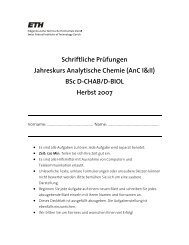
The experimental setup <strong>of</strong> the experimental air purify<strong>in</strong>g system<br />
is shown <strong>in</strong> Fig. 1A. The air flow is from left to right and the<br />
first component (1) is a HEPA (filter class H13, camfil, Re<strong>in</strong>feld,<br />
Germany) filter which purifies the air before it enters the system<br />
to make sure that no contam<strong>in</strong>ation from the outside is collected.<br />
Component (2) is the fan (Vortice L<strong>in</strong>eo 125 V0, VORTICE, Tribiano,<br />
Italy) generat<strong>in</strong>g an air flow which is cont<strong>in</strong>uously adjustable from<br />
0 to 360 m 3 h 1 . An <strong>in</strong>terface (3) made <strong>of</strong> polyv<strong>in</strong>yl chloride (PVC),<br />
connects the fan (<strong>in</strong>ner diameter (ID) 125 mm) to the ADP (ID<br />
150.6 mm). The tube <strong>in</strong> the middle <strong>of</strong> the system with the two w<strong>in</strong>dows<br />
is a 40 cm long PVC tube (5) with an ID <strong>of</strong> 150.6 mm which<br />
conta<strong>in</strong>s two <strong>in</strong>lets: one for the nitrogen gas to operate the nebulizer,<br />
and the second one to a motor driven syr<strong>in</strong>ge pump which<br />
provides the sample solution for the nebulizer. The nebulizer (4) itself<br />
is located exactly <strong>in</strong> the middle <strong>of</strong> the system to generate the<br />
best homogeneous nebulization possible. The two w<strong>in</strong>dows allow<br />
observ<strong>in</strong>g and adjust<strong>in</strong>g the nebulizer spray for optimiz<strong>in</strong>g it. The<br />
water content <strong>of</strong> the <strong>in</strong>com<strong>in</strong>g air was cont<strong>in</strong>uously measured with<br />
a hygrometer (Extech 445815, Conrad, Switzerland).<br />
Fig. 1B shows an exploded view <strong>of</strong> the ADP. Dimensions and<br />
technical specifications are: diameter 160 mm, length 180 mm;<br />
overall weight 10.5 kg; materials <strong>of</strong> construction: nickel, lead, copper,<br />
PVC and poly-(methyl-methacrylate); power consumption:<br />
17.3 W (root-mean-square); power supply: 230 V, 50 Hz. An operat<strong>in</strong>g<br />
voltage <strong>of</strong> 8 kV was used to maximize the degradation efficiency;<br />
the normal recommended operat<strong>in</strong>g voltage is 6.1 kV,<br />
result<strong>in</strong>g <strong>in</strong> much less O 3 production. The plasma is generated <strong>in</strong><br />
normal air without any auxiliary gas. The air velocity <strong>in</strong> the system<br />
is measured with an anemometer (PCE group, Germany) before<br />
and after the ADP. The sampl<strong>in</strong>g funnel (C) with an ID <strong>of</strong><br />
52.5 mm is located exactly <strong>in</strong> the middle <strong>of</strong> the 20 cm long tube<br />
at the end and will be discussed later. The other end <strong>of</strong> the sampl<strong>in</strong>g<br />
device is connected to adsorb<strong>in</strong>g tubes which are coupled<br />
to a vacuum pump (DIVAC membrane pump 2.2 L, Wexford, Ireland).<br />
The aspirated flow was measured with a flow meter and<br />
was varied between 0.1 and 3.5 L m<strong>in</strong> 1 by us<strong>in</strong>g a pressure reduc<strong>in</strong>g<br />
valve. An ozone monitor (Model C-30ZK, Ecosensors, Netherlands)<br />
was placed after the air outlet <strong>of</strong> our setup (after No. 9 <strong>in</strong><br />
Fig. 1A) for ozone detection.<br />
2.2. Sample <strong>in</strong>troduction/nebulization<br />
For sample nebulization a system similar to a sonic spray ionization<br />
source (Takats et al., 2003) was constructed. A fused silica<br />
capillary with an ID <strong>of</strong> 150 lm and an outer diameter (OD) <strong>of</strong><br />
375 lm was used for sample <strong>in</strong>fusion. The capillary for the nebuliz<strong>in</strong>g<br />
gas had an ID <strong>of</strong> 530 lm and an OD <strong>of</strong> 700 lm. Both capillaries<br />
were sealed <strong>in</strong> a sta<strong>in</strong>less steel T-piece (Swagelok) with<br />
polytetrafluoroethylene (PTFE) ferrules. A 1.5875 mm (1/16”) SS<br />
tub<strong>in</strong>g was used to deliver the nebuliz<strong>in</strong>g gas. This home-made<br />
nebulizer was fixed <strong>in</strong> the center <strong>of</strong> tube (4) (cf. Fig. 1A). Nitrogen<br />
was used as nebulizer gas, and the flow rate was varied from 0.45<br />
to 1.25 L m<strong>in</strong> 1 . A syr<strong>in</strong>ge pump (model 4400–001, Harvard Apparatus,<br />
USA) was used for sample <strong>in</strong>troduction. The sett<strong>in</strong>gs <strong>of</strong> the<br />
syr<strong>in</strong>ge pump were the follow<strong>in</strong>g: diameter, 14.57 mm; sample<br />
flow speed, 5–20 lL m<strong>in</strong> 1 ; target volume 2000, 500 or 250 lL.<br />
The sample nebulization with this technique was found to be very<br />
reproducible (stable spray and good area coverage <strong>of</strong> the ADP) and<br />
the sample flow rate as well as the sampl<strong>in</strong>g time could simply be<br />
adjusted us<strong>in</strong>g a syr<strong>in</strong>ge pump. The usage <strong>of</strong> a syr<strong>in</strong>ge (1010 LTN<br />
10 mL, HAMILTON, Boeckten, Switzerland) made <strong>of</strong> glass did not<br />
allow high sample flow rates (not higher than 500 lL m<strong>in</strong> 1 ) due<br />
to the high back pressure from the capillary (ID 150 lm). With a<br />
0.2 g L 1 solution <strong>of</strong> brilliant <strong>of</strong> blue R (Bio-Rad Laboratories,<br />
USA) the optimum spray distance was experimentally determ<strong>in</strong>ed.<br />
By spray<strong>in</strong>g the blue dye solution onto a white paper, an optimum<br />
distance <strong>of</strong> 40 cm was found, at which the whole cross section <strong>of</strong><br />
the ADP was covered.<br />
2.3. Sampl<strong>in</strong>g approach<br />
Fig. 1. (A) Schematic <strong>of</strong> the air purify<strong>in</strong>g system setup. (1), HEPA filter; (2),<br />
cont<strong>in</strong>uously adjustable fan (0–360 m 3 h 1 ); (3), polyv<strong>in</strong>yl chloride (PVC) <strong>in</strong>terface;<br />
(4), Nebulizer; (5), 400 mm long PVC tube with two Plexiglas w<strong>in</strong>dows; (6), holes<br />
for measur<strong>in</strong>g the air velocity with an anemometer; (7), 200 mm long PVC tube; (9),<br />
PVC tube connected with a funnel for the collection <strong>of</strong> the <strong>compounds</strong> after the ADP.<br />
(B) Exploded view <strong>of</strong> the plasma air purifier (Askokoro, Switzerland); (8), specially<br />
designed copper plates where AC high voltage is applied; (9), Plexiglas spacers. (C)<br />
Schematic <strong>of</strong> the sampl<strong>in</strong>g system; (10), PVC holder; (11), poly(tetrafluorethylene)<br />
(PTFE) funnel OD 52.5 mm and ID 49 mm; (12), O-r<strong>in</strong>g seals allow the connection<br />
with a 6 mm ID PTFE tube; (13), PTFE tube with an ID <strong>of</strong> 6 mm connected to the<br />
sampl<strong>in</strong>g tubes; (14), alum<strong>in</strong>um block to fix the PTFE funnel with the PVC tube.<br />
The sampl<strong>in</strong>g funnel (Fig. 1C) was placed 150 mm beh<strong>in</strong>d the<br />
ADP and was fixed <strong>in</strong>side the system by a PVC holder. The funnel<br />
(11) was made <strong>of</strong> PTFE and was connected to the PVC holder (10)<br />
<strong>in</strong>side an alum<strong>in</strong>um block (14) via an O-r<strong>in</strong>g seal (12) that allows<br />
a tight connection with a PTFE tube (13, ID 6 mm, which is exactly<br />
the <strong>in</strong>ner diameter <strong>of</strong> the funnel). This is to avoid any gaps and<br />
edges, where sample could accumulate. The other end <strong>of</strong> this PTFE<br />
tube (ID 6 mm) is connected to trapp<strong>in</strong>g media <strong>in</strong> tubes, which are<br />
coupled to the high vacuum pump. Two types <strong>of</strong> adsorbents were