Product specification - HFC Technics
Product specification - HFC Technics
Product specification - HFC Technics

You also want an ePaper? Increase the reach of your titles
YUMPU automatically turns print PDFs into web optimized ePapers that Google loves.
<strong>Product</strong> <strong>specification</strong> AC9000<br />
Kari Mäki 4.4.2012 1(7)<br />
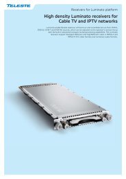
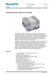
AC9000 INTELLIGENT FIBRE OPTIC PLATFORM<br />
Features<br />
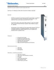
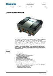
The AC9000 is an intelligent 4 output optical node of ACx product family. It is<br />
based on fixed platform but flexible modular solution, supporting up to two<br />
optical receivers, four optical transmitters and dual power supplies. The optical<br />
receivers can act as 2 independent nodes or in 1+1 backup operation.<br />
The 4 independent upstream inputs are connected to optical transmitters via a<br />
configurable signal routing matrix which allows flexible backup operations.<br />
The AC9000 has a slot for transponder module, allowing remote configuration<br />
and management of the node. The transponder unit also measures the DS and<br />
US signal levels used by the automatic alignment function. Forward and return<br />
path automatic alignment function increases the reliability of the node to a even<br />
higher level. Fully configurable automatic level control (ALC) keeps output level<br />
constant and automatic ingress blocking reacts to unwanted return path signals.<br />
− 1 GHz<br />
− Amplifiers stages use GaN HEMT and GaAs pHEMT technology<br />
− Innovative splice organizing<br />
− Redundant power supplies<br />
− Full electrical controls<br />
− Automatic alignment for both forward and return path<br />
− Automatic power saving operation mode<br />
− Downstream and upstream spectrum analyser function as an option<br />
− Flexible electrically controlled downstream and upstream signal routing<br />
− Support for digital return path transmitters<br />
− Wide range of upstream laser technologies available<br />
− Efficient surge and ESD protection<br />
AC9000_spec_v26
<strong>Product</strong> <strong>specification</strong> AC9000<br />
Kari Mäki 4.4.2012 2(7)<br />
Technical <strong>specification</strong>s<br />
Parameter<br />
Specification<br />
Downstream signal path<br />
Light wavelength<br />
1290…1610 nm<br />
Optical input power range<br />
- 7…0 dBm<br />
Frequency range<br />
70...1006 MHz<br />
Return loss 20 dB 1)<br />
Gain limited output level 4 x 112 dBµV / 2 x 116 dBµV 2)<br />
1 st interstage gain control 0…-16 dB 3)<br />
2 nd interstage gain control 0…-13 dB 4)<br />
Level offset,outputs 2 and 4 0…-15 dB 5)<br />
Slope control 0…20 dB 6)<br />
Isolation between DS paths > 60 dB 7)<br />
Flatness ±0.5 dB 8)<br />
Group delay 2 ns 9)<br />
Test point -20 dB 10)<br />
Transponder connection<br />
-19 dB<br />
Noise current density 5.5 pA/√Hz 11)<br />
CTB 41 channels 116.0 dBµV 12)<br />
CSO 41 channels 116.0 dBµV 12)<br />
XMOD 41 channels 112.5 dBµV 12)<br />
CTB 105 / 72 channels 78.0 / 85.0 dB 13)<br />
CSO 105 / 72 channels 74.0 / 81.0 dB 13)<br />
XMOD 105 / 72 channels 68.0 / 76.0 dB 13)<br />
Upstream signal path<br />
Frequency range<br />
5...85 MHz<br />
Return loss<br />
18 dB<br />
Ingress switching<br />
0 / -6 / < -45 dB<br />
Input level 57.0 dBµV 14)<br />
CINR > 52 dBc 15)<br />
OMI adjustment<br />
0…-20 dB<br />
OMI test point -5 dB 16)<br />
Transponder connection -37 dB 17)<br />
Isolation between US paths > 55 dB 18)<br />
General<br />
Power consumption 39...61 W 19)<br />
Supply voltage<br />
30...65 V AC<br />
Maximum current feed through<br />
12.0 A / port<br />
Hum modulation 70 dB 20)<br />
Optical connectors SC/APC, FC/APC, E-2000<br />
Output connectors<br />
PG11<br />
Test point connectors<br />
F female<br />
Dimensions 33(36) x 31(35) x 14 cm h x w x d<br />
Weight<br />
10 kg<br />
Operating temperature -40...+55 °C<br />
Class of enclosure IP 54<br />
EMC<br />
EN50083-2<br />
ESD 4 kV 21)<br />
Surge 6 kV (EN 60728-3)<br />
AC9000_spec_v26
<strong>Product</strong> <strong>specification</strong> AC9000<br />
Kari Mäki 4.4.2012 3(7)<br />
Notes<br />
1) The limiting curve is defined at 40 MHz -1.5 dB / octave. Return loss is always better than 13<br />
dB.<br />
2) This is the gain limited output level when OMI is 4.0 %. The level is available with -7 dBm optical<br />
input power (AC66B10). The used wavelength is 1310 nm. Higher output levels are possible if<br />
optical input level is higher than -7 dBm.<br />
3) Step size is 1 dB.<br />
4) Step size is 0.2 dB. This control is used by ALC.<br />
5) Step size is 1.0 dB. Adjusted with JDA series attenuators. There is an automatic 0 dB bypass<br />
built on motherboard in the case of missing JDA plug.<br />
6) Step size is 0.5 dB. Slope is defined between 47…1006 MHz. Flatness spec is guaranteed<br />
when slope is less than 16 dB.<br />
7) Defined 70…900 MHz. In higher frequencies the limit is 50 dB.<br />
8) Typical value in room temperature. Guaranteed value is ±0.75 dB.<br />
9) F > 125 MHz, BW 4.43 MHz.<br />
10) TP has ±0.75 dB tolerance between 70…862 MHz and ±1.0 dB between 862…1006 MHz.<br />
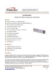
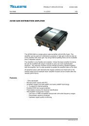
11) This is a typical value at 862 MHz and the value can be used for C/N calculations. Typical C/N<br />
curves can be seen in the picture.<br />
C/N (dB)<br />
60,0<br />
58,0<br />
Fibre link C/N<br />
Channel Bandwidth 4,75 MHz<br />
56,0<br />
54,0<br />
52,0<br />
50,0<br />
48,0<br />
46,0<br />
44,0<br />
RIN -155 dBc/Hz<br />
Fibre 10 km<br />
OMI / 1 channel<br />
OMI = 10%<br />
OMI = 8%<br />
OMI = 6%<br />
OMI = 5%<br />
OMI = 4%<br />
OMI = 3%<br />
42,0<br />
Noise current density 5,5 pA/sqrt(Hz)<br />
40,0<br />
0<br />
Responsivity 0,85 A/W<br />
-1 -2 -3<br />
-4<br />
-5<br />
-6<br />
-7<br />
-8<br />
-9<br />
-10<br />
Receiver input power (dBm)<br />
12) EN50083-3. In 2 output mode (=not splitted). Node output 8 dB cable equivalent sloped and<br />
optical input level -7 dBm. All results are typical values in room temperature. XMOD is<br />
measured at the lowest channel.<br />
The highest recommended output level for the node is 116 dBµV with 41 channels.<br />
13) In 2 output mode (=not splitted). Measured with 72 and 105 NTSC channels. The output 11 dB<br />
linearly sloped and the used levels at 120 / 550 / 750 / 862 MHz 36.0 / 42.5 / 45.5 / 47.0 dBmV.<br />
All results are typical values in room temperature, which can be used in system calculations.<br />
XMOD is measured at the lowest channel.<br />
The highest recommended output level for the node is 54 dBmV with 105 channels and 56<br />
dBmV with 72 channels.<br />
14) Nominal input level for 4.0 % OMI. Defined at the output connector of the node.<br />
AC9000_spec_v26
<strong>Product</strong> <strong>specification</strong> AC9000<br />
Kari Mäki 4.4.2012 4(7)<br />
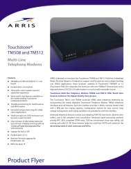
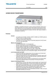
15)<br />
55.0 dB<br />
Curve is defined with CWDM transmitter (nominal performance in room temperature)<br />
Load 5 x 6.4 MHz, tested @ 49 MHz, Optical input level -2 dBm<br />
CINR<br />
50.0 dB<br />
45.0 dB<br />
40.0 dB<br />
35.0 dB<br />
-25 -20 -15 -10 -5 0 5 10<br />
Input Level (dBuV / Hz)<br />
Nominal performance when 65 MHz US channel is in use.<br />
16) - 5 dB is valid if ingress switch and US input attenuator are set to 0 dB.<br />
The nominal value at this TP is 52 dBuV when OMI is set to 4 %. Tested at 20 MHz.<br />
17) This is the level difference between return path input and transponder transmit pin when return<br />
path attenuation is 0 dB. This value increases linearly with increasing return path attenuation.<br />
18) Defined 5…65 MHz.<br />
19) 61 W: single PSU, transponder, 4 * optical CWDM TX, 2 * optical RX, full RF performance.<br />
39 W: single PSU, 1 * optical CWDM TX, 1 * optical RX, power save mode.<br />
20) 70 dB hum value is valid at any frequency from 10 to 1006 MHz, when the remote current is<br />
less than 8.0 A/port. Hum modulation is 65 dB, if 12.0 A is fed.<br />
20.0 A is the maximum current which can be locally injected into all ports together.<br />
21) EN61000-4-2, contact discharge to enclosure and RF-ports.<br />
AC9000_spec_v26
<strong>Product</strong> <strong>specification</strong> AC9000<br />
Kari Mäki 4.4.2012 5(7)<br />
Monitoring functions<br />
− Status LED for alarm indication<br />
− Return path ingress switches on / attenuated / off control<br />
− 65 VAC voltage measurement with alarms<br />
− Local +12 V and +24 V voltage measurements with alarms<br />
− Internal temperature measurement with alarms<br />
− Full electrical control of all forward and return path alignments<br />
− OMI based forward path automatic alignment<br />
− OMI based return path automatic alignment<br />
− Uptime, total uptime and reset counters for power outage statistics<br />
− User notes can be stored into amplifier memory<br />
− Fully user configurable alarm limits, severities, enabling and delays<br />
− Alarm log stored into non-volatile memory for easy troubleshooting<br />
− Node configuration and accessory information stored in amplifier memory<br />
− Fast local software update via USB also without power supply<br />
− Optical receiver input power measurement with alarms<br />
− Optical transmitter laser bias current monitoring with alarms<br />
− Automatic or manual optical receiver selection<br />
− Optical transmitter pilot generator enabling and frequency control<br />
− Return path signal combining / separation control with automatic backup<br />
Additional features available with AC6991 transponder:<br />
− Remote access to all AC9000 settings and monitored parameters<br />
− ALSC and modem LEDs for alarm indication<br />
− CATVisor and HMS compatible remote connection for monitoring and control<br />
− Interstage gain control by ALC mode with saturation alarm<br />
− ALC pilot frequencies, types, back-offs and decision levels are user<br />
programmable<br />
− Automatic reserve pilot switching<br />
− User configurable all pilots lost behaviour<br />
− Pilot based forward path automatic alignment<br />
− Full forward and return path automatic alignment with single button<br />
− Lid status monitoring with alarm<br />
− Service terminal connection monitoring with alarm<br />
− Node configuration change monitoring with alarm<br />
− Spectrum analyser for forward path level measurement with alarm<br />
− Ingress analyser for return path level measurement with alarms<br />
− Automatic ingress switch activation and deactivation based on detected<br />
ingress with alarms and user configurable delays<br />
− Modem receive and transmit signal level monitoring with alarms<br />
− Remote software update to multiple units simultaneously<br />
− Return path 4 pilot generator with user programmable frequencies and levels<br />
AC9000_spec_v26
<strong>Product</strong> <strong>specification</strong> AC9000<br />
Kari Mäki 4.4.2012 6(7)<br />
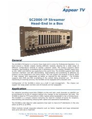
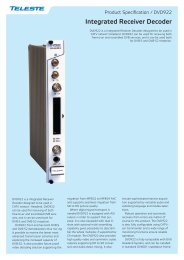
Block diagram<br />
Receiver 1<br />
O<br />
dB<br />
E<br />
dB<br />
Receiver 2<br />
O<br />
dB<br />
E<br />
dB<br />
dB<br />
Transponder<br />
TX<br />
RX<br />
LEVEL<br />
MEAS<br />
dB<br />
OMI test<br />
Transmitter 1<br />
O<br />
E<br />
dB<br />
dB<br />
0 / -6 /-50dB<br />
Transmitter 2<br />
O<br />
E<br />
Transmitter 3<br />
O<br />
E<br />
dB dB<br />
0 / -6 /-50dB<br />
dB dB<br />
0 / -6 /-50dB<br />
Transmitter 4<br />
O<br />
E<br />
dB<br />
dB<br />
0 / -6 /-50dB<br />
TP/<br />
Test Injection<br />
AC<br />
TP/<br />
Test Injection<br />
AC<br />
TP/<br />
Test Injection<br />
AC<br />
TP/<br />
Test Injection<br />
AC<br />
OUT 4<br />
OUT 3<br />
OUT 2<br />
OUT 1<br />
AC9000_spec_v26
<strong>Product</strong> <strong>specification</strong> AC9000<br />
Kari Mäki 4.4.2012 7(7)<br />
Ordering information<br />
AC9000 configuration map<br />
1- 2- 3- 4- 5- 6- 7- 8- 9- 10- 11- 12- 13-<br />
1 2 3 1 2 3 4 5 6 1 3 1 3 1 1 3 4 6 1 3 1 3 4 6 1 3 1 1 1 2 3 1 2<br />
AC9000 - - - - - - - - - - - -<br />
1-1 Platform type 6-4 Digital return path transmitter TX1 8-4 Digital return path transmitter TX2<br />
A Standard 1 GHz 27 +5 dBm CWDM 1270 nm (AC7727) 27 +5 dBm CWDM 1270 nm (AC7727)<br />
1-2 Power supply 29 +5 dBm CWDM 1290 nm (AC7729) 29 +5 dBm CWDM 1290 nm (AC7729)<br />
A Single PSU, 65 VAC 31 +5 dBm CWDM 1310 nm (AC7731) 31 +5 dBm CWDM 1310 nm (AC7731)<br />
B Double PSUs, 65 VAC 33 +5 dBm CWDM 1330 nm (AC7733) 33 +5 dBm CWDM 1330 nm (AC7733)<br />
1-3 Fiber organicing 35 +5 dBm CWDM 1350 nm (AC7735) 35 +5 dBm CWDM 1350 nm (AC7735)<br />
A Standard fibre organiser 37 +5 dBm CWDM 1370 nm (AC7737) 37 +5 dBm CWDM 1370 nm (AC7737)<br />
39 +5 dBm CWDM 1390 nm (AC7739) 39 +5 dBm CWDM 1390 nm (AC7739)<br />
2-1 Fibre feed-through adapter 1 (left) 41 +5 dBm CWDM 1410 nm (AC7741) 41 +5 dBm CWDM 1410 nm (AC7741)<br />
E 5/8 Adapter (KDC316) 43 +5 dBm CWDM 1430 nm (AC7743) 43 +5 dBm CWDM 1430 nm (AC7743)<br />
G 1-4 fibres (KDO900) 45 +5 dBm CWDM 1450 nm (AC7745) 45 +5 dBm CWDM 1450 nm (AC7745)<br />
X None 47 +5 dBm CWDM 1470 nm (AC7747) 47 +5 dBm CWDM 1470 nm (AC7747)<br />
2-2 Fibre feed-through adapter 2 (right) 49 +5 dBm CWDM 1490 nm (AC7749) 49 +5 dBm CWDM 1490 nm (AC7749)<br />
E 5/8 Adapter (KDC316) 51 +5 dBm CWDM 1510 nm (AC7751) 51 +5 dBm CWDM 1510 nm (AC7751)<br />
G 1-4 fibres (KDO900) 53 +5 dBm CWDM 1530 nm (AC7753) 53 +5 dBm CWDM 1530 nm (AC7753)<br />
X None 55 +5 dBm CWDM 1550 nm (AC7755) 55 +5 dBm CWDM 1550 nm (AC7755)<br />
2-3 Output 1 connection (first from right) 57 +5 dBm CWDM 1570 nm (AC7757) 57 +5 dBm CWDM 1570 nm (AC7757)<br />
A PG11 59 +5 dBm CWDM 1590 nm (AC7759) 59 +5 dBm CWDM 1590 nm (AC7759)<br />
B 5/8" 61 +5 dBm CWDM 1610 nm (AC7761) 61 +5 dBm CWDM 1610 nm (AC7761)<br />
C IEC XX None XX None<br />
D 3.5/12 6-6 Optical connector for Digital transmitter TX1 8-6 Optical connector for Digital transmitter TX2<br />
E F A SC/APC, 9 deg. A SC/APC, 9 deg.<br />
X None (PG11 sealing plug) B FC/APC, 8 deg. B FC/APC, 8 deg.<br />
2-4 Output 2 connection C E-2000 C E-2000<br />
A PG11 D SC/APC, 8 deg. D SC/APC, 8 deg.<br />
B 5/8" X None X None<br />
C IEC<br />
D 3.5/12 7-1 Return path transmitter TX2 9-1 Return path transmitter TX4<br />
E F 40 +1 dBm FP 1310 nm (AC67B40) 40 +1 dBm FP 1310 nm (AC67B40)<br />
X None (PG11 sealing plug) 41 +3 dBm CWDM 1430 nm (AC67B41) 41 +1 dBm FP 1310 nm (AC67B40)<br />
2-5 Output 3 connection 42 +6 dBm CWDM 1430 nm (AC67B42) 42 +3 dBm CWDM 1430 nm (AC67B41)<br />
A PG11 43 +3 dBm CWDM 1450 nm (AC67B43) 43 +6 dBm CWDM 1430 nm (AC67B42)<br />
B 5/8" 44 +6 dBm CWDM 1450 nm (AC67B44) 44 +3 dBm CWDM 1450 nm (AC67B43)<br />
C IEC 45 +3 dBm DFB 1310 nm (AC67B45) 45 +6 dBm CWDM 1450 nm (AC67B44)<br />
D 3.5/12 46 +6 dBm DFB 1310 nm (AC67B46) 46 +3 dBm DFB 1310 nm (AC67B45)<br />
E F 47 +3 dBm CWDM 1470 nm (AC67B47) 47 +6 dBm DFB 1310 nm (AC67B46)<br />
X None (PG11 sealing plug) 48 +6 dBm CWDM 1470 nm (AC67B48) 48 +6 dBm CWDM 1470 nm (AC67B48)<br />
2-6 Output 4 connection (first from left) 49 +3 dBm CWDM 1490 nm (AC67B49) 49 +3 dBm CWDM 1490 nm (AC67B49)<br />
A PG11 50 +6 dBm CWDM 1490 nm (AC67B50) 50 +6 dBm CWDM 1490 nm (AC67B50)<br />
B 5/8" 51 +3 dBm CWDM 1510 nm (AC67B51) 51 +3 dBm CWDM 1510 nm (AC67B51)<br />
C IEC 52 +6 dBm CWDM 1510 nm (AC67B52) 52 +6 dBm CWDM 1510 nm (AC67B52)<br />
D 3.5/12 53 +3 dBm CWDM 1530 nm (AC67B53) 53 +3 dBm CWDM 1530 nm (AC67B53)<br />
E F 54 +6 dBm CWDM 1530 nm (AC67B54) 54 +6 dBm CWDM 1530 nm (AC67B54)<br />
X None (PG11 sealing plug) 55 +3 dBm CWDM 1550 nm (AC67B55) 55 +3 dBm CWDM 1550 nm (AC67B55)<br />
56 +6 dBm CWDM 1550 nm (AC67B56) 56 +6 dBm CWDM 1550 nm (AC67B56)<br />
3-1 Optical receiver RX1 57 +3 dBm CWDM 1570 nm (AC67B57) 57 +3 dBm CWDM 1570 nm (AC67B57)<br />
10 RX1 input level -7...0 dBm (AC66B10) 58 +6 dBm CWDM 1570 nm (AC67B58) 58 +6 dBm CWDM 1570 nm (AC67B58)<br />
XX None 59 +3 dBm CWDM 1590 nm (AC67B59) 59 +3 dBm CWDM 1590 nm (AC67B59)<br />
3-3 Optical connector for receiver RX1 60 +6 dBm CWDM 1590 nm (AC67B60) 60 +6 dBm CWDM 1590 nm (AC67B60)<br />
A SC/APC, 9 deg. 61 +3 dBm CWDM 1610 nm (AC67B61) 61 +3 dBm CWDM 1610 nm (AC67B61)<br />
B FC/APC, 8 deg. 62 +6 dBm CWDM 1610 nm (AC67B62) 62 +6 dBm CWDM 1610 nm (AC67B62)<br />
C E-2000 XX None XX None<br />
D SC/APC, 8 deg. 7-3 Optical connector for transmitter TX2 9-3 Optical connector for transmitter TX4<br />
X None A SC/APC, 9 deg. A SC/APC, 9 deg.<br />
B FC/APC, 8 deg. B FC/APC, 8 deg.<br />
4-1 Optical receiver RX2 C E-2000 C E-2000<br />
10 RX2 input level -7...0 dBm (AC66B10) D SC/APC, 8 deg. D SC/APC, 8 deg.<br />
XX None X None X None<br />
4-3 Optical connector for receiver RX2<br />
A SC/APC, 9 deg. 8-1 Return path transmitter TX3 10-1 Optical passive<br />
B FC/APC, 8 deg. 40 +1 dBm FP 1310 nm (AC67B40) XX None<br />
C E-2000 41 +1 dBm FP 1310 nm (AC67B40) F1 WDM and 1490 nm Add Drop with 9 deg. SC/APC connectors<br />
D SC/APC, 8 deg. 42 +3 dBm CWDM 1430 nm (AC67B41) F2 WDM with 8 deg. SC/APC connectors<br />
X None 43 +6 dBm CWDM 1430 nm (AC67B42) M1 MUX with SC/APC connectors<br />
44 +3 dBm CWDM 1450 nm (AC67B43) M2 MUX with SC/APC connectors<br />
5-1 Diplexer filter 45 +6 dBm CWDM 1450 nm (AC67B44) M3 MUX with SC/APC connectors<br />
C 50/70 MHz (4 x CXF050) 46 +3 dBm DFB 1310 nm (AC67B45) M4 MUX with SC/APC connectors<br />
D 65/85 MHz (4 x CXF065) 47 +6 dBm DFB 1310 nm (AC67B46) M5 MUX with SC/APC connectors<br />
F 55/70 MHz (4 x CXF055) 48 +6 dBm CWDM 1470 nm (AC67B48)<br />
G 65/85 MHz (4 x CXF065 18) 49 +3 dBm CWDM 1490 nm (AC67B49) 11-1 Transponder module<br />
H 85/108 MHz (4 x CXF085 FM) 50 +6 dBm CWDM 1490 nm (AC67B50) B Transponder and ALSC module (AC6991)<br />
X None 51 +3 dBm CWDM 1510 nm (AC67B51) X None<br />
52 +6 dBm CWDM 1510 nm (AC67B52)<br />
6-1 Return path transmitter TX1 53 +3 dBm CWDM 1530 nm (AC67B53) 12-1 Application software<br />
40 +1 dBm FP 1310 nm (AC67B40) 54 +6 dBm CWDM 1530 nm (AC67B54) A CATVisor compatible<br />
41 +1 dBm FP 1310 nm (AC67B40) 55 +3 dBm CWDM 1550 nm (AC67B55) B HMS compatible<br />
42 +3 dBm CWDM 1430 nm (AC67B41) 56 +6 dBm CWDM 1550 nm (AC67B56) 12-2 Settings<br />
43 +6 dBm CWDM 1430 nm (AC67B42) 57 +3 dBm CWDM 1570 nm (AC67B57) X Factory default<br />
44 +3 dBm CWDM 1450 nm (AC67B43) 58 +6 dBm CWDM 1570 nm (AC67B58) A Customer specified<br />
45 +6 dBm CWDM 1450 nm (AC67B44) 59 +3 dBm CWDM 1590 nm (AC67B59) 12-3 <strong>Product</strong> keys (software features)<br />
46 +3 dBm DFB 1310 nm (AC67B45) 60 +6 dBm CWDM 1590 nm (AC67B60) X None<br />
47 +6 dBm DFB 1310 nm (AC67B46) 61 +3 dBm CWDM 1610 nm (AC67B61) A Plug'n'play forward path alignment<br />
48 +6 dBm CWDM 1470 nm (AC67B48) 62 +6 dBm CWDM 1610 nm (AC67B62) B Spectrum and ingress analyser functionality<br />
49 +3 dBm CWDM 1490 nm (AC67B49) XX None C A + B + Return path pilot generator<br />
50 +6 dBm CWDM 1490 nm (AC67B50) 8-3 Optical connector for transmitter TX3<br />
51 +3 dBm CWDM 1510 nm (AC67B51) A SC/APC, 9 deg. 13-1 Installation manual<br />
52 +6 dBm CWDM 1510 nm (AC67B52) B FC/APC, 8 deg. X None<br />
53 +3 dBm CWDM 1530 nm (AC67B53) C E-2000 A Manual<br />
54 +6 dBm CWDM 1530 nm (AC67B54) D SC/APC, 8 deg. 13-2 Reserved for future<br />
55 +3 dBm CWDM 1550 nm (AC67B55) X None X None<br />
56 +6 dBm CWDM 1550 nm (AC67B56)<br />
57 +3 dBm CWDM 1570 nm (AC67B57)<br />
58 +6 dBm CWDM 1570 nm (AC67B58)<br />
59 +3 dBm CWDM 1590 nm (AC67B59)<br />
60 +6 dBm CWDM 1590 nm (AC67B60)<br />
61 +3 dBm CWDM 1610 nm (AC67B61)<br />
62 +6 dBm CWDM 1610 nm (AC67B62)<br />
XX None<br />
6-3 Optical connector for transmitter TX1<br />
A<br />
B<br />
SC/APC, 9 deg.<br />
FC/APC, 8 deg.<br />
C E-2000<br />
D<br />
X<br />
SC/APC, 8 deg.<br />
None<br />
DOC0018989, Rev011<br />
AC9000_spec_v26