Damage of Bridges Resulting from Surface Rupture of Faults in the ...
Damage of Bridges Resulting from Surface Rupture of Faults in the ...
Damage of Bridges Resulting from Surface Rupture of Faults in the ...

Create successful ePaper yourself
Turn your PDF publications into a flip-book with our unique Google optimized e-Paper software.
Acceleration (g)<br />
0.6<br />
0.3<br />
0<br />
-0.3<br />
-0.6<br />
EW<br />
Max=-0.42G<br />
Acceleration (g)<br />
0.3<br />
0<br />
UD<br />
Max=0.26G<br />
-0.3<br />
0 5 10 15 20 25<br />
Time (sec)<br />
1.5<br />
Acceleration (g)<br />
1<br />
0.5<br />
<br />
EW<br />
UD<br />
Fig. 5 Arfiye Bridge <br />
0<br />
0 1 2 3 4 5<br />
Period (sec)<br />
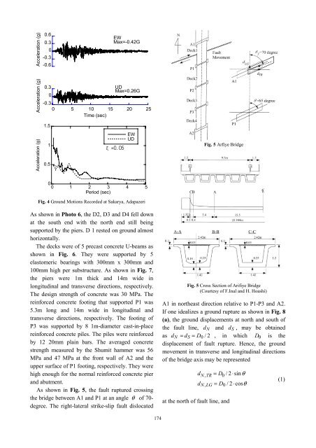
Fig. 4 Ground Motions Recorded at Sakarya, Adapazeri<br />
As shown <strong>in</strong> Photo 6, <strong>the</strong> D2, D3 and D4 fell down<br />
at <strong>the</strong> south end with <strong>the</strong> north end still be<strong>in</strong>g<br />
supported by <strong>the</strong> piers. D 1 rested on ground almost<br />
horizontally.<br />
The decks were <strong>of</strong> 5 precast concrete U-beams as<br />
shown <strong>in</strong> Fig. 6. They were supported by 5<br />
elastomeric bear<strong>in</strong>gs with 300mm x 300mm and<br />
100mm high per substructure. As shown <strong>in</strong> Fig. 7,<br />
<strong>the</strong> piers were 1m thick and 14m wide <strong>in</strong><br />
longitud<strong>in</strong>al and transverse directions, respectively.<br />
The design strength <strong>of</strong> concrete was 30 MPa. The<br />
re<strong>in</strong>forced concrete foot<strong>in</strong>g that supported P1 was<br />
5.3m long and 14m wide <strong>in</strong> longitud<strong>in</strong>al and<br />
transverse directions, respectively. The foot<strong>in</strong>g <strong>of</strong><br />
P3 was supported by 8 1m-diameter cast-<strong>in</strong>-place<br />
re<strong>in</strong>forced concrete piles. The piles were re<strong>in</strong>forced<br />
by 12 20mm pla<strong>in</strong> bars. The averaged concrete<br />
strength measured by <strong>the</strong> Shumit hammer was 56<br />
MPa and 47 MPa at <strong>the</strong> front wall <strong>of</strong> A2 and <strong>the</strong><br />
upper surface <strong>of</strong> P1 foot<strong>in</strong>g, respectively. They were<br />
high enough for <strong>the</strong> normal re<strong>in</strong>forced concrete pier<br />
and abutment.<br />
As shown <strong>in</strong> Fig. 5, <strong>the</strong> fault ruptured cross<strong>in</strong>g<br />
<strong>the</strong> bridge between A1 and P1 at an angle θ <strong>of</strong> 70-<br />
degree. The right-lateral strike-slip fault dislocated<br />
Fig. 5 Cross Section <strong>of</strong> Arifiye Bridge<br />
(Courtesy <strong>of</strong> F.Inal and H. Hoashi)<br />
A1 <strong>in</strong> nor<strong>the</strong>ast direction relative to P1-P3 and A2.<br />
If one idealizes a ground rupture as shown <strong>in</strong> Fig. 8<br />
(a), <strong>the</strong> ground displacements at north and south <strong>of</strong><br />
<strong>the</strong> fault l<strong>in</strong>e, d N and d S , may be obta<strong>in</strong>ed<br />
as d N = d S = D 0 /2 , <strong>in</strong> which D 0 is <strong>the</strong><br />
displacement <strong>of</strong> fault rupture. Hence, <strong>the</strong> ground<br />
movement <strong>in</strong> transverse and longitud<strong>in</strong>al directions<br />
<strong>of</strong> <strong>the</strong> bridge axis may be represented<br />
d N,TR = D 0 /2⋅s<strong>in</strong>θ<br />
d N,LG = D 0 /2⋅cosθ<br />
at <strong>the</strong> north <strong>of</strong> fault l<strong>in</strong>e, and<br />
(1)<br />
174