Selection and Operation of Wireless Microphone ... - SLD Mediatec
Selection and Operation of Wireless Microphone ... - SLD Mediatec
Selection and Operation of Wireless Microphone ... - SLD Mediatec

Create successful ePaper yourself
Turn your PDF publications into a flip-book with our unique Google optimized e-Paper software.
9W I RELESS M I CROPHONE S Y STEMS: DE SCRIPTION<br />
C HAPTER 2<br />
boost the low voltage up to the desired operating value.<br />
Battery life varies widely among transmitters, from just a<br />
few hours up to twenty hours, depending on output power,<br />
battery type, <strong>and</strong> overall circuit efficiency.<br />
RECEIVER: GENERAL DESCRIPTION<br />
Receivers are available in both fixed <strong>and</strong> portable<br />
designs. Portable receivers resemble portable transmitters<br />
externally: they are characterized by small size, one or two<br />
outputs (microphone/line, headphone), minimal controls <strong>and</strong><br />
indicators (power, level), <strong>and</strong> (usually) a single antenna.<br />
Internally they are functionally similar to fixed receivers,<br />
again with the exception <strong>of</strong> the power supply (battery vs.<br />
AC). The important features <strong>of</strong> receivers will be presented<br />
in the context <strong>of</strong> fixed units, which exhibit a greater range <strong>of</strong><br />
choices.<br />
Fixed receivers <strong>of</strong>fer various<br />
outward features: units may be free<br />
st<strong>and</strong>ing or rack-mountable; outputs<br />
may include balanced/unbalanced<br />
microphone or line level as well as<br />
headphones; indicators for power<br />
<strong>and</strong> audio/radio signal level may be<br />
present; controls for power <strong>and</strong> out<br />
put level are usually <strong>of</strong>fered; antennas<br />
may be removable or permanently<br />
attached.<br />
Like transmitters, receivers can<br />
vary greatly in packaging, but inside<br />
they must achieve a common goal:<br />
receive the radio signal efficiently<br />
<strong>and</strong> convert it into a suitable audio<br />
signal output. Once again it will be<br />
useful to look at the main functional<br />
elements <strong>of</strong> the typical receiver.<br />
RECEIVER: RADIO CIRCUITRY<br />
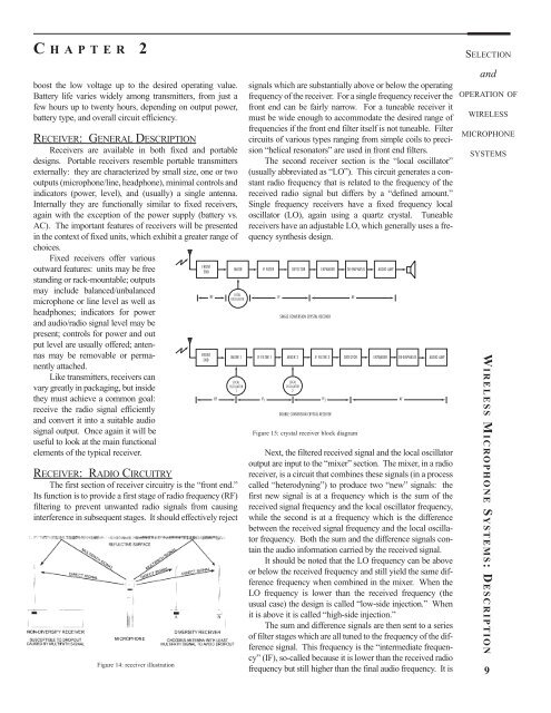
The first section <strong>of</strong> receiver circuitry is the “front end.”<br />
Its function is to provide a first stage <strong>of</strong> radio frequency (RF)<br />
filtering to prevent unwanted radio signals from causing<br />
interference in subsequent stages. It should effectively reject<br />
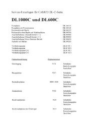
Figure 14: receiver illustration<br />
FRONT<br />
END<br />
FRONT<br />
END<br />
signals which are substantially above or below the operating<br />
frequency <strong>of</strong> the receiver. For a single frequency receiver the<br />
front end can be fairly narrow. For a tuneable receiver it<br />
must be wide enough to accommodate the desired range <strong>of</strong><br />
frequencies if the front end filter itself is not tuneable. Filter<br />
circuits <strong>of</strong> various types ranging from simple coils to precision<br />
“helical resonators” are used in front end filters.<br />
The second receiver section is the “local oscillator”<br />
(usually abbreviated as “LO”). This circuit generates a constant<br />
radio frequency that is related to the frequency <strong>of</strong> the<br />
received radio signal but differs by a “defined amount.”<br />
Single frequency receivers have a fixed frequency local<br />
oscillator (LO), again using a quartz crystal. Tuneable<br />
receivers have an adjustable LO, which generally uses a frequency<br />
synthesis design.<br />
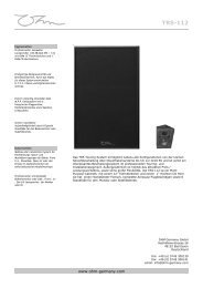
MIXER IF FILTER DETECTOR EXPANDER DE-EMPHASIS AUDIO AMP<br />
LOCAL<br />
RF IF AF<br />
OSCILLATOR<br />
SINGLE CONVERSION CRYSTAL RECEIVER<br />
MIXER 1 IF FILTER 1 MIXER 2 IF FILTER 2 DETECTOR EXPANDER<br />
LOCAL<br />
OSCILLATOR<br />
1<br />
LOCAL<br />
OSCILLATOR<br />
2<br />
RF IF 1 IF 2<br />
DOUBLE CONVERSION CRYSTAL RECEIVER<br />
Figure 15: crystal receiver block diagram<br />
DE-EMPHASIS<br />
AUDIO AMP<br />
Next, the filtered received signal <strong>and</strong> the local oscillator<br />
output are input to the “mixer” section. The mixer, in a radio<br />
receiver, is a circuit that combines these signals (in a process<br />
called “heterodyning”) to produce two “new” signals: the<br />
first new signal is at a frequency which is the sum <strong>of</strong> the<br />
received signal frequency <strong>and</strong> the local oscillator frequency,<br />
while the second is at a frequency which is the difference<br />
between the received signal frequency <strong>and</strong> the local oscillator<br />
frequency. Both the sum <strong>and</strong> the difference signals contain<br />
the audio information carried by the received signal.<br />
It should be noted that the LO frequency can be above<br />
or below the received frequency <strong>and</strong> still yield the same difference<br />
frequency when combined in the mixer. When the<br />
LO frequency is lower than the received frequency (the<br />
usual case) the design is called “low-side injection.” When<br />
it is above it is called “high-side injection.”<br />
The sum <strong>and</strong> difference signals are then sent to a series<br />
<strong>of</strong> filter stages which are all tuned to the frequency <strong>of</strong> the difference<br />
signal. This frequency is the “intermediate frequency”<br />
(IF), so-called because it is lower than the received radio<br />
frequency but still higher than the final audio frequency. It is<br />
AF<br />
SELECTION<br />
<strong>and</strong><br />
OPERATION OF<br />
WIRELESS<br />
MICROPHONE<br />
SYSTEMS