Selection and Operation of Wireless Microphone ... - SLD Mediatec
Selection and Operation of Wireless Microphone ... - SLD Mediatec
Selection and Operation of Wireless Microphone ... - SLD Mediatec

Create successful ePaper yourself
Turn your PDF publications into a flip-book with our unique Google optimized e-Paper software.
C HAPTER 2<br />
greater the number <strong>of</strong> elements the greater is the b<strong>and</strong>width<br />
<strong>and</strong> the directivity.<br />
Although these directional antennas are somewhat large<br />
(3-5 ft. wide for VHF) <strong>and</strong> may be mechanically cumbersome<br />
to mount, they can provide increased range <strong>and</strong> greater<br />
rejection <strong>of</strong> interfering sources for certain applications. It<br />
should also be noted here that these antennas should be oriented<br />
with the transverse elements in the vertical direction<br />
rather than the horizontal direction (as would be used for<br />
television reception), again because the transmitting antennas<br />
are usually also vertical.<br />
require repeated setups. Finally, the number <strong>of</strong> connections in<br />
the antenna signal path should be kept to a minimum.<br />
ANTENNA DISTRIBUTION<br />
The last component found in some (larger) wireless<br />
microphone systems is some form <strong>of</strong> antenna signal distribution.<br />
It is <strong>of</strong>ten desirable to reduce the total number <strong>of</strong><br />
antennas in multiple systems by distributing the signal from<br />
one set <strong>of</strong> antennas to several receivers. This is usually done<br />
Antenna A<br />
Antenna B<br />
SELECTION<br />
<strong>and</strong><br />
OPERATION OF<br />
WIRELESS<br />
MICROPHONE<br />
SYSTEMS<br />
ANTENNA CABLE<br />
An important but <strong>of</strong>ten overlooked component <strong>of</strong> many<br />
wireless microphone systems is the antenna cable.<br />
Applications in which the receiver is located away from the<br />
transmitter vicinity <strong>and</strong>/or within metal racks will require the<br />
use <strong>of</strong> remote antennas <strong>and</strong> connecting cables. Compared to<br />
audio frequency signals, the nature <strong>of</strong> radio frequency signal<br />
propagation in cables is such that significant losses can occur<br />
in relatively short lengths <strong>of</strong> cable. The loss is a function <strong>of</strong><br />
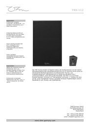
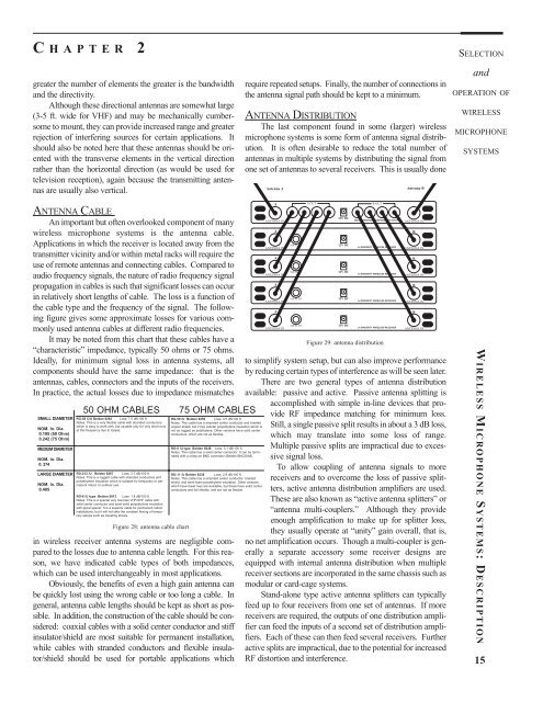
the cable type <strong>and</strong> the frequency <strong>of</strong> the signal. The following<br />
figure gives some approximate losses for various commonly<br />
used antenna cables at different radio frequencies.<br />
It may be noted from this chart that these cables have a<br />
“characteristic” impedance, typically 50 ohms or 75 ohms.<br />
Ideally, for minimum signal loss in antenna systems, all<br />
components should have the same impedance: that is the<br />
antennas, cables, connectors <strong>and</strong> the inputs <strong>of</strong> the receivers.<br />
In practice, the actual losses due to impedance mismatches<br />
50 OHM CABLES 75 OHM CABLES<br />
SMALL DIAMETER RG-58 C/U Belden 8262 Loss: 7.5 dB/100 ft.<br />
Notes: This is a very flexible cable with str<strong>and</strong>ed conductors<br />
which is easy to work with, but usuable only for very short runs<br />
NOM. In. Dia. at this frequency due to losses.<br />
0.195 (50 Ohm)<br />
0.242 (75 Ohm)<br />
MEDIUM DIAMETER<br />
NOM. In. Dia.<br />
0. 274<br />
LARGE DIAMETER RG-213 /U Belden 8267 Loss: 2.7 dB/100 ft.<br />
Notes: This is a rugged cable with str<strong>and</strong>ed conductors <strong>and</strong><br />
polyethylene insulation which is suitable for temporary or permanent<br />
indoor or outdoor use.<br />
NOM. In. Dia.<br />
0.405<br />
RG-8 /U type Belden 9913 Loss: 1.8 dB/100 ft.<br />
Notes: This is a special very low-loss VHF/UHF cable with<br />
solid center conductor <strong>and</strong> semi-solid polyethylene insulation<br />
with spiral spacer. It is a superior cable for permanent indoor<br />
installations, but it will not take the constant flexing <strong>of</strong> temporary<br />
setups such as traveling shows.<br />
Figure 28: antenna cable chart<br />
RG-59 /U Belden 9259 Loss: 4.5 dB/100 ft<br />
Notes: This cable has a str<strong>and</strong>ed center conductor <strong>and</strong> braided<br />
copper shield, but it has cellular polyehtylene insulation which is<br />
not as rugged as polythylene. Other versions have solid center<br />
conductors, which are not as flexible.<br />
RG-6 /U type Belden 9248 Loss: 3.1 dB/100 ft<br />
Notes: This cable has a solid center conductor. It can be terminated<br />
with a crimp-on BNC connector (Belden BNC0048).<br />
RG-11 /U Belden 8238 Loss: 2.9 dB/100 ft.<br />
Notes: This cable has a str<strong>and</strong>ed center conductor, braided<br />
shield, <strong>and</strong> semi-foam polyethylene insulation. Other versions<br />
which have lower loss are available, but these have solid center<br />
conductors <strong>and</strong> foil shields, <strong>and</strong> are not as flexible.<br />
in wireless receiver antenna systems are negligible compared<br />
to the losses due to antenna cable length. For this reason,<br />
we have indicated cable types <strong>of</strong> both impedances,<br />
which can be used interchangeably in most applications.<br />
Obviously, the benefits <strong>of</strong> even a high gain antenna can<br />
be quickly lost using the wrong cable or too long a cable. In<br />
general, antenna cable lengths should be kept as short as possible.<br />
In addition, the construction <strong>of</strong> the cable should be considered:<br />
coaxial cables with a solid center conductor <strong>and</strong> stiff<br />
insulator/shield are most suitable for permanent installation,<br />
while cables with str<strong>and</strong>ed conductors <strong>and</strong> flexible insulator/shield<br />
should be used for portable applications which<br />
A<br />
ANTENNA IN<br />
A<br />
ANTENNA IN<br />
A<br />
ANTENNA IN<br />
A<br />
ANTENNA IN<br />
A<br />
ANTENNA IN<br />
SQUELCH<br />
SQUELCH<br />
SQUELCH<br />
SQUELCH<br />
A OUT<br />
12V DC<br />
12V DC<br />
12V DC<br />
12V DC<br />
12V DC<br />
WA400 ANTENNAE DISTRIBUTION SYSTEM<br />
L4 DIVERSITY WIRELESS RECEIVER<br />
L4 DIVERSITY WIRELESS RECEIVER<br />
L4 DIVERSITY WIRELESS RECEIVER<br />
L4 DIVERSITY WIRELESS RECEIVER<br />
to simplify system setup, but can also improve performance<br />
by reducing certain types <strong>of</strong> interference as will be seen later.<br />
There are two general types <strong>of</strong> antenna distribution<br />
available: passive <strong>and</strong> active. Passive antenna splitting is<br />
accomplished with simple in-line devices that provide<br />
RF impedance matching for minimum loss.<br />
Still, a single passive split results in about a 3 dB loss,<br />
which may translate into some loss <strong>of</strong> range.<br />
Multiple passive splits are impractical due to excessive<br />
signal loss.<br />
To allow coupling <strong>of</strong> antenna signals to more<br />
receivers <strong>and</strong> to overcome the loss <strong>of</strong> passive splitters,<br />
active antenna distribution amplifiers are used.<br />
These are also known as “active antenna splitters” or<br />
“antenna multi-couplers.” Although they provide<br />
enough amplification to make up for splitter loss,<br />
they usually operate at “unity” gain overall, that is,<br />
no net amplification occurs. Though a multi-coupler is generally<br />
a separate accessory some receiver designs are<br />
equipped with internal antenna distribution when multiple<br />
receiver sections are incorporated in the same chassis such as<br />
modular or card-cage systems.<br />
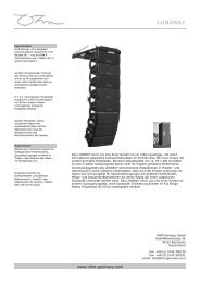
St<strong>and</strong>-alone type active antenna splitters can typically<br />
feed up to four receivers from one set <strong>of</strong> antennas. If more<br />
receivers are required, the outputs <strong>of</strong> one distribution amplifier<br />
can feed the inputs <strong>of</strong> a second set <strong>of</strong> distribution amplifiers.<br />
Each <strong>of</strong> these can then feed several receivers. Further<br />
active splits are impractical, due to the potential for increased<br />
RF distortion <strong>and</strong> interference.<br />
B OUT<br />
Figure 29: antenna distribution<br />
ANTENNA IN<br />
B<br />
ANTENNA IN<br />
B<br />
ANTENNA IN<br />
B<br />
ANTENNA IN<br />
B<br />
ANTENNA IN<br />
W IRELESS M ICROPHONE S YSTEMS:DESCRIPTION<br />
15