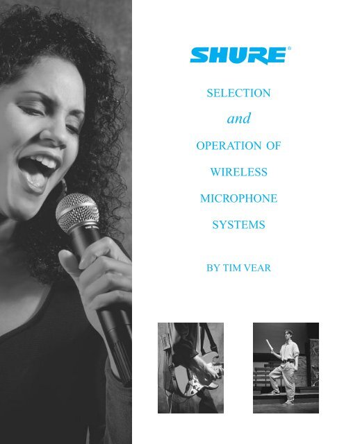
Selection and Operation of Wireless Microphone ... - SLD Mediatec
Selection and Operation of Wireless Microphone ... - SLD Mediatec
Selection and Operation of Wireless Microphone ... - SLD Mediatec

You also want an ePaper? Increase the reach of your titles
YUMPU automatically turns print PDFs into web optimized ePapers that Google loves.
®<br />
SELECTION<br />
<strong>and</strong><br />
OPERATION OF<br />
WIRELESS<br />
MICROPHONE<br />
SYSTEMS<br />
BY TIM VEAR
T ABLE OF C ONTENTS<br />
Introduction . . . . . . . . . . . . . . . . . . . . . . . . . . . . . . . . . . . . . . . . . . . . . . . . . . 2<br />
WIRELESS MICROPHONE SYSTEMS: HOW THEY WORK . . . . . 3<br />
Radio Transmission . . . . . . . . . . . . . . . . . . . . . . . . . . . . . . . . . . . . . . . . . . . . 3<br />
WIRELESS MICROPHONE SYSTEMS: DESCRIPTION . . . . . . . . . . . 5<br />
Input Source . . . . . . . . . . . . . . . . . . . . . . . . . . . . . . . . . . . . . . . . . . . . . . . . . . 6<br />
Transmitter: General Description . . . . . . . . . . . . . . . . . . . . . . . . . . . . . . . . . . 6<br />
Transmitter: Audio Circuitry . . . . . . . . . . . . . . . . . . . . . . . . . . . . . . . . . . . . . 7<br />
Transmitter: Radio Circuitry . . . . . . . . . . . . . . . . . . . . . . . . . . . . . . . . . . . . . . 8<br />
Receiver: General Description . . . . . . . . . . . . . . . . . . . . . . . . . . . . . . . . . . . . 9<br />
Receiver: Radio Circuitry . . . . . . . . . . . . . . . . . . . . . . . . . . . . . . . . . . . . . . . . 9<br />
Receiver: Audio Circuitry . . . . . . . . . . . . . . . . . . . . . . . . . . . . . . . . . . . . . . . 10<br />
Receiver: Squelch . . . . . . . . . . . . . . . . . . . . . . . . . . . . . . . . . . . . . . . . . . . . 10<br />
Diversity . . . . . . . . . . . . . . . . . . . . . . . . . . . . . . . . . . . . . . . . . . . . . . . . . . . 11<br />
Antennas . . . . . . . . . . . . . . . . . . . . . . . . . . . . . . . . . . . . . . . . . . . . . . . . . . . 13<br />
Antenna Cable . . . . . . . . . . . . . . . . . . . . . . . . . . . . . . . . . . . . . . . . . . . . . . . 15<br />
Antenna Distribution . . . . . . . . . . . . . . . . . . . . . . . . . . . . . . . . . . . . . . . . . . 15<br />
SELECTION<br />
<strong>and</strong><br />
OPERATION OF<br />
WIRELESS<br />
MICROPHONE<br />
SYSTEMS<br />
FREQUENCY BANDS FOR WIRELESS MICROPHONE SYSTEMS . . . 16<br />
VHF . . . . . . . . . . . . . . . . . . . . . . . . . . . . . . . . . . . . . . . . . . . . . . . . . . . . . . . 16<br />
UHF . . . . . . . . . . . . . . . . . . . . . . . . . . . . . . . . . . . . . . . . . . . . . . . . . . . . . . . 17<br />
Frequency <strong>Selection</strong> . . . . . . . . . . . . . . . . . . . . . . . . . . . . . . . . . . . . . . . . . . . 18<br />
System Compatibility . . . . . . . . . . . . . . . . . . . . . . . . . . . . . . . . . . . . . . . . . . 18<br />
Operating Frequencies: Intermodulation . . . . . . . . . . . . . . . . . . . . . . . . . . . . 18<br />
Internal Frequencies: LO, IF, Crystal Multipliers . . . . . . . . . . . . . . . . . . . . . 21<br />
Non-system Radio Interference . . . . . . . . . . . . . . . . . . . . . . . . . . . . . . . . . . 22<br />
Broadcast Television . . . . . . . . . . . . . . . . . . . . . . . . . . . . . . . . . . . . . . . . . . 22<br />
Broadcast Radio . . . . . . . . . . . . . . . . . . . . . . . . . . . . . . . . . . . . . . . . . . . . . . 23<br />
Other Radio Services . . . . . . . . . . . . . . . . . . . . . . . . . . . . . . . . . . . . . . . . . . 23<br />
Non-broadcast Sources . . . . . . . . . . . . . . . . . . . . . . . . . . . . . . . . . . . . . . . . . 26<br />
Spread Spectrum . . . . . . . . . . . . . . . . . . . . . . . . . . . . . . . . . . . . . . . . . . . . . 26<br />
Range <strong>of</strong> <strong>Wireless</strong> <strong>Microphone</strong> Systems . . . . . . . . . . . . . . . . . . . . . . . . . . . . 27<br />
WIRELESS MICROPHONE SYSTEMS:<br />
HOW TO MAKE THEM WORK . . . . . . . . . . . . . . . . . . . . . . . 28<br />
System <strong>Selection</strong> . . . . . . . . . . . . . . . . . . . . . . . . . . . . . . . . . . . . . . . . . . . . . 28<br />
Crystal Controlled vs. Frequency Synthesis . . . . . . . . . . . . . . . . . . . . . . . . . 28<br />
System Setup: Transmitter . . . . . . . . . . . . . . . . . . . . . . . . . . . . . . . . . . . . . . 29<br />
System Setup: Receivers . . . . . . . . . . . . . . . . . . . . . . . . . . . . . . . . . . . . . . . 31<br />
System Setup: Receiver Antennas . . . . . . . . . . . . . . . . . . . . . . . . . . . . . . . . . 32<br />
System Setup: Batteries . . . . . . . . . . . . . . . . . . . . . . . . . . . . . . . . . . . . . . . . 33<br />
System Checkout <strong>and</strong> <strong>Operation</strong> . . . . . . . . . . . . . . . . . . . . . . . . . . . . . . . . . . 33<br />
Troubleshooting <strong>Wireless</strong> <strong>Microphone</strong> Systems . . . . . . . . . . . . . . . . . . . . . . 34<br />
Application Notes . . . . . . . . . . . . . . . . . . . . . . . . . . . . . . . . . . . . . . . . . . . . 34<br />
Presenters . . . . . . . . . . . . . . . . . . . . . . . . . . . . . . . . . . . . . . . . . . . . . . . . . . . 36<br />
Musical Instruments . . . . . . . . . . . . . . . . . . . . . . . . . . . . . . . . . . . . . . . . . . . 36<br />
Vocalists . . . . . . . . . . . . . . . . . . . . . . . . . . . . . . . . . . . . . . . . . . . . . . . . . . . . 37<br />
Aerobic/Dance Instruction . . . . . . . . . . . . . . . . . . . . . . . . . . . . . . . . . . . . . . 37<br />
Theater . . . . . . . . . . . . . . . . . . . . . . . . . . . . . . . . . . . . . . . . . . . . . . . . . . . . . 37<br />
Worship . . . . . . . . . . . . . . . . . . . . . . . . . . . . . . . . . . . . . . . . . . . . . . . . . . . . 38<br />
Bingo . . . . . . . . . . . . . . . . . . . . . . . . . . . . . . . . . . . . . . . . . . . . . . . . . . . . . . 38<br />
Film/Videography . . . . . . . . . . . . . . . . . . . . . . . . . . . . . . . . . . . . . . . . . . . . .39<br />
Broadcast . . . . . . . . . . . . . . . . . . . . . . . . . . . . . . . . . . . . . . . . . . . . . . . . . . . 39<br />
Large Room/Multi-Room Applications . . . . . . . . . . . . . . . . . . . . . . . . . . . . . 40<br />
Conclusion . . . . . . . . . . . . . . . . . . . . . . . . . . . . . . . . . . . . . . . . . . . . . . . . . . 40<br />
REFERENCE INFORMATION . . . . . . . . . . . . . . . . . . . . . . . . . . 41<br />
Glossary <strong>of</strong> Terms <strong>and</strong> Specifications . . . . . . . . . . . . . . . . . . . . . . . . . . . . . . 41<br />
Suggested Reading . . . . . . . . . . . . . . . . . . . . . . . . . . . . . . . . . . . . . . . . . . . . 44<br />
Biography . . . . . . . . . . . . . . . . . . . . . . . . . . . . . . . . . . . . . . . . . . . . . . . . . . 44<br />
TABLE OF C ONTENTS<br />
1
SELECTION<br />
<strong>and</strong><br />
OPERATION OF<br />
WIRELESS<br />
MICROPHONE<br />
SYSTEMS<br />
I NTRODUCTION<br />
The many uses <strong>of</strong> wireless microphone systems can span applications<br />
from live entertainment to earth-orbit communications. It can<br />
include devices from a single “Mr. <strong>Microphone</strong>” to a 60 channel theme<br />
park system. It can evoke visions <strong>of</strong> freedom in prospective users <strong>and</strong><br />
memories <strong>of</strong> ancient disaster in veteran sound engineers. In all its<br />
forms, wireless has become a fact <strong>of</strong> life for people who design <strong>and</strong><br />
use audio systems. With increased use <strong>of</strong> wireless microphone systems<br />
has come the need for increased quantity <strong>and</strong> quality <strong>of</strong> information<br />
on the topic.<br />
The scope <strong>of</strong> this guide is limited to wireless microphone systems<br />
used in audio applications. The reader is presumed to be somewhat<br />
familiar with basic audio. However, since wireless microphone systems<br />
depend upon certain general principles <strong>of</strong> radio, some information<br />
on basic radio is included. While there are similarities between<br />
sound transmission <strong>and</strong> radio transmission, many <strong>of</strong> the characteristics<br />
<strong>of</strong> radio systems are neither analogous to audio systems nor intuitive.<br />
Still, though perhaps new, the key ideas are fairly straightforward.<br />
The purpose <strong>of</strong> this guide is to provide the interested reader with<br />
adequate information to select suitable wireless equipment for a given<br />
application <strong>and</strong> to use that equipment successfully. In addition, it is<br />
hoped that the fundamentals presented here will equip regular users <strong>of</strong><br />
wireless with a framework to assist in their further underst<strong>and</strong>ing <strong>of</strong><br />
this evolving technology.<br />
I NTRODUCTION<br />
2<br />
This guide is presented in two parts: how wireless microphone<br />
systems work <strong>and</strong> how to make wireless microphone systems work.<br />
The first part is a technical introduction to the basic principles <strong>of</strong> radio<br />
<strong>and</strong> to the characteristics <strong>of</strong> wireless transmitters <strong>and</strong> receivers. The<br />
second part discusses the practical selection <strong>and</strong> operation <strong>of</strong> wireless<br />
microphone systems for general <strong>and</strong> specific applications. The two<br />
parts are intended to be self-contained. The first part should be <strong>of</strong><br />
interest to those who specify or integrate pr<strong>of</strong>essional wireless equipment<br />
while the second part should be <strong>of</strong> use to anyone who regularly<br />
works with wireless microphone systems.
3W I RELESS M I CROPHONE S Y STEMS: HOW T H EY WORK<br />
C HAPTER 1<br />
WIRELESS MICROPHONE SYSTEMS:<br />
HOW THEY WORK<br />
RADIO TRANSMISSION<br />
Radio refers to a class <strong>of</strong> time-varying electromagnetic<br />
fields created by varying voltages <strong>and</strong>/or currents in certain<br />
physical sources. These sources may be “artificial,” such as<br />
electrical power <strong>and</strong> electronic circuits, or “natural,” such as<br />
the atmosphere (lightning) <strong>and</strong> stars (sunspots). The electromagnetic<br />
field variations radiate outward from the source<br />
forming a pattern called a radio wave. Thus, a radio wave is<br />
a series <strong>of</strong> electromagnetic field variations travelling through<br />
space. Although, technically, any varying source <strong>of</strong> voltage<br />
or current produces a varying field near the source, here the<br />
term “radio wave” describes field variations that propagate a<br />
significant distance from the source.<br />
A sound wave has only a single “field” component (air<br />
pressure). Variations in this component create a pattern <strong>of</strong> air<br />
pressure changes along the direction that the sound wave<br />
travels but otherwise have no particular orientation. In contrast,<br />
a radio wave includes both an electric field component<br />
<strong>and</strong> a magnetic field component. The variations in these<br />
components have the same relative pattern along the direction<br />
that the radio wave travels but they are oriented at a 90<br />
degree angle to each other as illustrated in the accompanying<br />
figure. In particular, it is the orientation <strong>of</strong> the electric field<br />
component which determines the angle <strong>of</strong> “polarization” <strong>of</strong><br />
the radio wave. This becomes especially important to the<br />
design <strong>and</strong> operation <strong>of</strong> antennas.<br />
Figure 1: radio wave<br />
Like sound, a radio wave can be described by its frequency<br />
<strong>and</strong> its amplitude. The frequency <strong>of</strong> a radio wave is<br />
the time rate <strong>of</strong> the field variations measured in Hertz (Hz),<br />
where 1 Hz equals 1 cycle-per-second. The radio spectrum,<br />
or range <strong>of</strong> frequencies, extends from a few Hertz through<br />
the Kilohertz (KHz) <strong>and</strong> Megahertz (MHz) ranges, to<br />
beyond the Gigahertz (GHz) range. The suffixes KHz,<br />
MHz, <strong>and</strong> GHz refer to thous<strong>and</strong>s, millions, <strong>and</strong> billions <strong>of</strong><br />
cycles-per-second respectively. As far as is presently known,<br />
humans are directly sensitive to radio waves only at frequencies<br />
in the range <strong>of</strong> a few million GHz, which are perceived<br />
as visible light, <strong>and</strong> at those frequencies in the range just<br />
below visible light, which are perceived as heat (infrared<br />
radiation). The overall radio spectrum includes both natural<br />
<strong>and</strong> artificial sources as indicated by Figure 2.<br />
Figure 2: radio frequency spectrum<br />
The amplitude <strong>of</strong> a radio wave is the magnitude <strong>of</strong> the<br />
field variations <strong>and</strong> is the characteristic that determines the<br />
“strength” <strong>of</strong> the radio wave. Specifically, it is defined to be<br />
the amplitude <strong>of</strong> the electric field variation. It is measured in<br />
volts per unit length <strong>and</strong> ranges from nanovolts/meter<br />
(nV/m) to kilovolts/meter (KV/m), where nV refers to one<br />
billionth <strong>of</strong> a volt <strong>and</strong> KV refers to one thous<strong>and</strong> volts. The<br />
minimum level required for pickup by a typical radio receiver<br />
is only a few tens <strong>of</strong> microvolts (uV, a millionth <strong>of</strong> a volt)<br />
but much higher levels can be found near transmitters <strong>and</strong><br />
other sources. The wide range <strong>of</strong> radio wave amplitudes that<br />
may be encountered in typical applications requires great<br />
care in the design <strong>and</strong> use <strong>of</strong> wireless microphone systems,<br />
particularly receivers.<br />
Another characteristic <strong>of</strong> radio waves, related to frequency,<br />
is wavelength. The wavelength is the physical distance<br />
between the start <strong>of</strong> one cycle <strong>and</strong> the start <strong>of</strong> the next<br />
cycle as the wave moves through space. Wavelength is related<br />
to frequency by the speed at which the radio wave travels.<br />
The speed <strong>of</strong> radio waves (in a vacuum) is equal to<br />
approximately 3 x 10 8 meter/sec, or about 186,000 miles/sec,<br />
the same as the speed <strong>of</strong> light. It does not change with frequency<br />
or wavelength but is related to them in the following<br />
way: the frequency <strong>of</strong> a radio wave, multiplied by its wavelength<br />
always equals the speed <strong>of</strong> light. Thus, the higher the<br />
radio frequency, the shorter the wavelength, <strong>and</strong> the lower the<br />
frequency, the longer the wavelength. Typical wavelengths<br />
for certain radio frequencies are given in Figure 3.<br />
Wavelength also has important consequences in the design<br />
<strong>and</strong> use <strong>of</strong> wireless microphone systems, particularly for<br />
antennas.<br />
Unlike sound, radio waves do not require a physical<br />
substance (such as air) for transmission. In fact, they “propagate”<br />
or travel most efficiently through the vacuum <strong>of</strong><br />
space. However, the speed <strong>of</strong> radio waves is somewhat slower<br />
when travelling through a medium other than vacuum.<br />
For example, visible light travels more slowly through glass<br />
than through air. This effect accounts for the “refraction” or<br />
bending <strong>of</strong> light by a lens. Radio waves can also be affected<br />
SELECTION<br />
<strong>and</strong><br />
OPERATION OF<br />
WIRELESS<br />
MICROPHONE<br />
SYSTEMS
4W I RELESS M I CROPHONE S Y STEMS: HOW T H EY WORK<br />
SELECTION<br />
<strong>and</strong><br />
OPERATION OF<br />
WIRELESS<br />
MICROPHONE<br />
SYSTEMS<br />
C HAPTER 1<br />
Figure 3: radio wavelength chart<br />
by the size <strong>and</strong> composition<br />
<strong>of</strong> objects in<br />
their path. In particular,<br />
they can be<br />
reflected by metal if<br />
the size <strong>of</strong> the metal<br />
object is comparable<br />
to or greater than the<br />
wavelength <strong>of</strong> the<br />
radio wave. Large<br />
surfaces can reflect<br />
both low frequency<br />
(long wavelength)<br />
<strong>and</strong> high frequency<br />
(short wavelength)<br />
waves, but small surfaces<br />
can reflect only<br />
high frequency<br />
(short) radio waves.<br />
Interestingly, a<br />
reflecting metal<br />
object can be porous,<br />
ie. it can have holes<br />
or spaces in it. As<br />
long as the holes are much smaller than the wavelength, the<br />
metal surface will behave as if it were solid. This means that<br />
screens, grids, bars, or other metal arrays can reflect radio<br />
waves whose wavelength is greater than the space between<br />
the array elements <strong>and</strong> less than the overall array size. If the<br />
space between elements is larger than the wavelength, the<br />
radio waves will pass through the array. The metal screen on<br />
the glass door <strong>of</strong> a microwave oven reflects microwaves<br />
back into the oven but allows (shorter) light waves to pass<br />
through so that the inside is visible.<br />
Even metal objects which are smaller than the wavelength<br />
are able to bend or “diffract” radio waves. Generally,<br />
the size, location, <strong>and</strong> quantity <strong>of</strong> metal in the vicinity <strong>of</strong><br />
radio waves will have significant effect on their behavior.<br />
Non-metallic substances (including air) do not reflect<br />
radio waves but are not completely transparent either. To<br />
some degree, they generally “attenuate” or cause a loss in the<br />
strength <strong>of</strong> radio waves that pass through them. The amount<br />
<strong>of</strong> attenuation or loss is a function <strong>of</strong> the thickness <strong>and</strong> composition<br />
<strong>of</strong> the material <strong>and</strong> also a function <strong>of</strong> the radio<br />
wavelength. In practice, dense materials produce more losses<br />
than lighter materials <strong>and</strong> long radio waves (low frequencies)<br />
can propagate greater distances through “lossy” materials<br />
than short radio waves (high frequencies). The human<br />
body causes significant losses to short radio waves passing<br />
through it.<br />
An object which is large enough to reflect radio waves<br />
or dense enough to attenuate them can create a “shadow” in<br />
the path <strong>of</strong> the waves which can greatly hamper reception <strong>of</strong><br />
radio in the area beyond the object.<br />
Figure 4: radio wave propagation vs. wavelength when<br />
encountering conductive obstacles.<br />
A final parallel between sound waves <strong>and</strong> radio waves<br />
lies in the nature <strong>of</strong> the radio wave pattern or “field” produced<br />
by various sources at a given location. If reflections<br />
are present (which is nearly always the case indoors), the<br />
radio field will include both direct waves (those that travel<br />
by the shortest path from the source to the location) <strong>and</strong> indirect<br />
waves (those that are reflected). Radio waves, like<br />
sound waves, become weaker as they travel away from their<br />
source, at a rate governed by the inverse-square law: at twice<br />
the distance, the strength is decreased by a factor <strong>of</strong> four (the<br />
square <strong>of</strong> two). The radio waves that arrive at a given location,<br />
by direct or indirect paths, have different amplitudes<br />
related to the strength <strong>of</strong> the original source(s) <strong>and</strong> the<br />
amount <strong>of</strong> loss due to reflections, material attenuation <strong>and</strong><br />
the total distance travelled.<br />
After many reflections radio waves become weaker <strong>and</strong><br />
essentially non-directional. They ultimately contribute to<br />
ambient radio “noise,” that is, general radio energy produced<br />
by many natural <strong>and</strong> man-made sources across a wide range<br />
<strong>of</strong> frequencies. The strength <strong>of</strong> ambient radio noise is relatively<br />
constant in a given area, that is, it does not diminish<br />
with distance. The total radio field at a given location consists<br />
<strong>of</strong> direct waves, indirect waves <strong>and</strong> radio noise.<br />
Radio noise is nearly always considered to be undesirable.<br />
The direct <strong>and</strong> indirect waves may come from both the<br />
desired source (the intended transmission) <strong>and</strong> undesirable<br />
sources (other transmissions <strong>and</strong> general radio energy emitters).<br />
Successful radio reception depends on a favorable<br />
level <strong>of</strong> the desired transmission compared to undesirable<br />
transmissions <strong>and</strong> noise.<br />
This discussion <strong>of</strong> radio transmission has so far dealt<br />
only with the basic radio wave. It is also necessary to consider<br />
how information is carried by these waves. Audio<br />
“information” is transmitted by sound waves which consist<br />
<strong>of</strong> air pressure variations over a large range <strong>of</strong> amplitudes<br />
<strong>and</strong> frequencies. This combination <strong>of</strong> varying amplitudes<br />
<strong>and</strong> varying frequencies creates a highly complex sound<br />
field. These varying pressure waves are able to be processed<br />
directly by our auditory systems to perceive speech, music,<br />
<strong>and</strong> other intelligible sounds (information).
C HAPTER 1<br />
Radio “information” is generally transmitted using only<br />
one frequency. This single electromagnetic wave is varied in<br />
amplitude, frequency, or some other characteristic (such as<br />
phase) <strong>and</strong> for most radio transmissions neither the wave nor<br />
its variation can be detected or processed directly by human<br />
senses. In fact, the wave itself is not the information but<br />
rather the “carrier” <strong>of</strong> the information. The information is<br />
actually contained in the amplitude variation or frequency<br />
variation, for example. When a radio wave contains information<br />
it is called a radio “signal.” The term for variation <strong>of</strong><br />
radio waves is “modulation.” If the amplitude <strong>of</strong> the wave<br />
is varied the technique is called Amplitude Modulation or<br />
AM. If the frequency is varied, it is called Frequency<br />
Modulation or FM.<br />
The amount <strong>of</strong> information that can be carried in a radio<br />
signal depends on the amount <strong>and</strong> type <strong>of</strong> modulation that<br />
can be applied to the basic radio wave as well as the base frequency<br />
<strong>of</strong> radio wave. This is limited by physics to some<br />
extent, but is also limited by regulatory agencies such as the<br />
FCC. For AM signals, the radio wave has a single (constant)<br />
frequency <strong>of</strong> some basic amplitude (determined by the transmitter<br />
power). This amplitude is varied up <strong>and</strong> down (modulated)<br />
by the audio signal to create the corresponding radio<br />
signal. The maximum (legal) amount <strong>of</strong> amplitude modulation<br />
allows an audio signal <strong>of</strong> only limited frequency<br />
response (about 50-9000 Hz) <strong>and</strong> limited dynamic range<br />
(about 50 dB).<br />
Figure 5: modulated AM carrier<br />
For FM signals, the radio wave has a constant amplitude<br />
(again determined by transmitter power) <strong>and</strong> a basic frequency.<br />
The basic radio frequency is varied up <strong>and</strong> down<br />
(modulated) by the audio signal to create the corresponding<br />
radio signal. This frequency modulation is called “deviation”<br />
since it causes the carrier to deviate up <strong>and</strong> down from<br />
its basic or unmodulated frequency.<br />
The deviation is a function <strong>of</strong> the amplitude <strong>of</strong> the audio<br />
signal <strong>and</strong> is usually measured in kilohertz (KHz). Typical<br />
values <strong>of</strong> deviation in wireless microphone systems range<br />
from about 12KHz to 45KHz depending on the operating<br />
frequency b<strong>and</strong>. The maximum (legal) amount <strong>of</strong> deviation<br />
allows an audio signal <strong>of</strong> greater frequency response (about<br />
50-15,000 Hz) <strong>and</strong> greater dynamic range (more than 90 dB)<br />
than does AM.<br />
Although the details <strong>of</strong> wireless microphone transmitters<br />
<strong>and</strong> receivers will be covered in the next section, it<br />
should be noted here that all <strong>of</strong> the systems discussed in this<br />
presentation use the FM technique. The reasons for this are<br />
the same as are apparent in commercial broadcast systems.<br />
More “information” can be sent in the typical FM signal,<br />
allowing higher fidelity audio signals to be transmitted. In<br />
addition, FM receivers are inherently less sensitive to many<br />
common sources <strong>of</strong> radio noise, such as lightning <strong>and</strong> electrical<br />
power equipment, because the AM component <strong>of</strong> such<br />
interference is rejected.<br />
WIRELESS MICROPHONE SYSTEMS:<br />
DESCRIPTION<br />
The function <strong>of</strong> a radio or “wireless” system is to send<br />
information in the form <strong>of</strong> a radio signal. In this presentation,<br />
the information is assumed to be an audio signal, but <strong>of</strong><br />
course video, data, or control signals can all be sent via radio<br />
waves. In each case, the information must be converted to a<br />
radio signal, transmitted, received, <strong>and</strong> converted back to its<br />
original form. The initial conversion consists <strong>of</strong> using the<br />
original information to create a radio signal by “modulating”<br />
a basic radio wave. In the final conversion, a complementary<br />
technique is used to “demodulate” the radio signal to<br />
recover the original information.<br />
Awireless microphone system consists generally <strong>of</strong> three<br />
main components: an input source, a transmitter, <strong>and</strong> a<br />
receiver. The input source provides an audio signal to the<br />
transmitter. The transmitter converts the audio signal to a<br />
radio signal <strong>and</strong> “broadcasts” or transmits it to the surrounding<br />
area. The receiver “picks up” or receives the radio signal <strong>and</strong><br />
converts it back into an audio signal. Additional system components<br />
include antennas <strong>and</strong>, possibly, antenna cables <strong>and</strong><br />
distribution systems. The processes <strong>and</strong> the basic components<br />
are functionally similar to commercial radio <strong>and</strong> television <strong>and</strong><br />
other forms <strong>of</strong> radio communications. What differs is the<br />
component scale <strong>and</strong> the physical system configurations.<br />
Figure 7: radio<br />
system diagram<br />
MICROPHONE<br />
OR OTHER<br />
SOURCE<br />
AUDIO<br />
SIGNAL<br />
TRANSMITTER<br />
Figure 6: modulated FM carrier<br />
RADIO<br />
SIGNAL<br />
RECEIVER<br />
AUDIO<br />
SIGNAL<br />
SOUND<br />
SYSTEM OR<br />
OTHER<br />
DESTINATION<br />
SELECTION<br />
<strong>and</strong><br />
OPERATION OF<br />
WIRELESS<br />
MICROPHONE<br />
SYSTEMS<br />
W IRELESS M ICROPHONE S YSTEMS:HOW T HEY WORK<br />
5
6W I RELESS M I CROPHONE S Y STEMS: DE SCRIPTION<br />
SELECTION<br />
<strong>and</strong><br />
OPERATION OF<br />
WIRELESS<br />
MICROPHONE<br />
SYSTEMS<br />
C HAPTER 2<br />
There are four basic configurations <strong>of</strong> wireless microphone<br />
systems, related to the mobility <strong>of</strong> the transmitter <strong>and</strong><br />
receiver components, as required for different applications.<br />
This presentation will focus on systems consisting <strong>of</strong> a<br />
portable transmitter <strong>and</strong> a stationary receiver. The transmitter<br />
is usually carried by the user, who is free to move about,<br />
while the receiver is located in a fixed position. The input<br />
source in this setup is normally a microphone or an electronic<br />
musical instrument. The receiver output is typically<br />
sent to a sound system, recording equipment, or a broadcast<br />
system. This is the configuration <strong>of</strong> the st<strong>and</strong>ard “wireless<br />
microphone” <strong>and</strong> is the arrangement most widely used in<br />
entertainment, public address, <strong>and</strong> broadcast applications.<br />
The second configuration employs a stationary transmitter<br />
<strong>and</strong> a portable receiver. In this case, the receiver is<br />
carried by the user, while the transmitter is fixed. The input<br />
source to the transmitter for these setups is usually a sound<br />
system, playback system, or other installed source. The output<br />
<strong>of</strong> the receiver is typically monitored through headphones<br />
or loudspeakers. It may feed a portable audio or<br />
video recorder. This is the configuration <strong>of</strong> wireless microphone<br />
systems for assistive listening, simultaneous translation,<br />
in-the-ear monitors, <strong>and</strong> various instructional uses. It is<br />
also, <strong>of</strong> course, the configuration <strong>of</strong> commercial radio <strong>and</strong><br />
television systems when the receiver is mobile such as a personal<br />
radio or a car radio.<br />
The third configuration consists <strong>of</strong> both a portable transmitter<br />
<strong>and</strong> a portable receiver. The users <strong>of</strong> both components<br />
are free to move about. Again, the input source is usually a<br />
microphone <strong>and</strong> the output is <strong>of</strong>ten a headphone. This is the<br />
configuration <strong>of</strong> “wireless intercom” systems, though each<br />
user in a typical setup has both a transmitter <strong>and</strong> a receiver<br />
for two-way communication. Another application <strong>of</strong> this<br />
configuration is for transmission <strong>of</strong> audio from a wireless<br />
microphone to a portable camera/recorder in broadcast, film,<br />
<strong>and</strong> videography.<br />
The fourth configuration comprises a transmitter <strong>and</strong> a<br />
receiver that are each stationary. The typical input would be<br />
a playback source or mixer while the output might be to a<br />
sound system or to a broadcast facility. Examples <strong>of</strong> this<br />
setup are wireless audio feeds to multiple amplifier/loudspeaker<br />
arrays for temporary distributed sound systems,<br />
radio remote-to-studio links <strong>and</strong> <strong>of</strong> course commercial <strong>and</strong><br />
non-commercial broadcasts from fixed transmitters to fixed<br />
receivers.<br />
INPUT SOURCE<br />
The input source is any device that provides a suitable<br />
audio signal to the transmitter. “Suitable audio signal”<br />
means an electrical signal within a certain frequency range<br />
(audio), voltage range (microphone level or line level), <strong>and</strong><br />
impedance range (low or high) that can be h<strong>and</strong>led by the<br />
transmitter. Though this places some limits on input sources,<br />
it will be seen that almost any type <strong>of</strong> audio signal can be<br />
used with one system or another.<br />
The most common input source is a microphone, which<br />
may take any one <strong>of</strong> a variety <strong>of</strong> forms: h<strong>and</strong>held, lavaliere,<br />
headworn, instrument-mounted, etc. The audio signal provided<br />
by this source is audio frequency, microphone level,<br />
<strong>and</strong> usually low impedance. Since the “wireless” part <strong>of</strong> the<br />
wireless microphone only serves to replace the cable, ideally,<br />
the characteristics <strong>and</strong> performance <strong>of</strong> a particular microphone<br />
should not change when used as part <strong>of</strong> a wireless<br />
microphone system.<br />
Therefore, the selection <strong>of</strong> microphone type for a wireless<br />
microphone system should be made following the same<br />
guidelines as for wired microphones. The usual choices <strong>of</strong><br />
operating principle (dynamic/condenser), frequency<br />
response (flat/shaped), directionality (omni-/uni-directional),<br />
electrical output (balanced/unbalanced, low or high impedance),<br />
<strong>and</strong> physical design (size, shape, mounting, etc.) must<br />
still be made. The problems that result from improper<br />
microphone choice will only be aggravated in a wireless<br />
application.<br />
Another widely encountered input source is an electronic<br />
musical instrument, such as an electric guitar, electric<br />
bass, or portable electronic keyboard. The signal from these<br />
sources is again audio frequency, microphone or line level,<br />
<strong>and</strong> usually high impedance. The potentially higher signal<br />
levels <strong>and</strong> high impedances can affect transmitter choice.<br />
Finally, general audio signal sources such as mixer outputs,<br />
cassette or CD players, etc. can be considered, though<br />
they exhibit a wide range <strong>of</strong> levels <strong>and</strong> impedances. As long<br />
as these characteristics are within the input capabilities <strong>of</strong> the<br />
transmitter they may be successfully used.<br />
TRANSMITTER: GENERAL DESCRIPTION<br />
Transmitters can be either fixed or portable as mentioned<br />
earlier. Regardless <strong>of</strong> type, transmitters usually feature a single<br />
audio input (line or microphone type), minimal controls<br />
<strong>and</strong> indicators (power, audio gain adjustment) <strong>and</strong> a single<br />
antenna. Internally, they are also functionally the same, except<br />
for the power supply: AC power for fixed types <strong>and</strong> battery<br />
power for portable models. The important features <strong>of</strong> transmitter<br />
design will be presented in the context <strong>of</strong> portable units.<br />
Figure 8: transmitter illustration<br />
Portable transmitters are available in three different<br />
forms: bodypack, h<strong>and</strong>held, <strong>and</strong> plug-on. Each <strong>of</strong> these has<br />
further variations <strong>of</strong> inputs, controls, indicators, <strong>and</strong> antennas.<br />
The choice <strong>of</strong> transmitter type is <strong>of</strong>ten dictated by the<br />
choice <strong>of</strong> input source: h<strong>and</strong>held microphones usually
7W I RELESS M I CROPHONE S Y STEMS: DE SCRIPTION<br />
C HAPTER 2<br />
require h<strong>and</strong>held or plug-on transmitters while nearly all<br />
other sources are used with bodypack types.<br />
Bodypack (sometimes called beltpack) transmitters are<br />
typically packaged in a shirt-pocket sized rectangular housing.<br />
They are <strong>of</strong>ten provided with a clip that secures to<br />
clothing or belt, or may be placed in a pocket or pouch. In<br />
theater <strong>and</strong> some other applications they may be concealed<br />
underneath clothing. Input is made from the source to the<br />
bodypack via a cable which may be permanently attached<br />
or detachable at a connector. This connector may allow a<br />
variety <strong>of</strong> input sources to be used with one transmitter.<br />
Bodypack transmitter controls include at least a power<br />
switch <strong>and</strong> usually a mute switch, allowing the audio input<br />
to be silenced without interrupting the radio signal. Other<br />
controls may include gain adjustment, attenuators, limiters<br />
<strong>and</strong>, in tuneable systems, a provision for frequency selection.<br />
Indicators (usually LED’s) for power-on <strong>and</strong> battery condition<br />
are common <strong>and</strong> desirable, while tuneable units sometimes<br />
include digital readouts <strong>of</strong> frequency. Finally, the<br />
antenna for a bodypack transmitter may be in the form <strong>of</strong> a<br />
flexible attached wire, a short “rubber duckie” type, or the<br />
input source cable itself, such as a guitar cable or lavaliere<br />
microphone cable.<br />
H<strong>and</strong>held transmitters, as the name implies, consist <strong>of</strong> a<br />
h<strong>and</strong>held vocal microphone element integrated with a transmitter<br />
built into the h<strong>and</strong>le. The complete package appears<br />
only slightly larger than a wired h<strong>and</strong>held microphone. It<br />
may be carried in the h<strong>and</strong> or mounted on a microphone<br />
st<strong>and</strong> using an appropriate swivel adapter. Input from the<br />
microphone element is direct via an internal connector or<br />
wires. Some models have removable or interchangeable<br />
microphone elements.<br />
H<strong>and</strong>held transmitter controls are generally limited to a<br />
power switch, a mute switch, <strong>and</strong> gain adjustment, though<br />
again, some models may include frequency selection.<br />
Indicators are comparable to those in bodypack transmitters.<br />
The antenna is usually concealed inside the h<strong>and</strong>held transmitter,<br />
though certain types (primarily UHF) use a short<br />
external antenna.<br />
“Plug-on” transmitters are a special type designed to<br />
attach directly to a typical h<strong>and</strong>held microphone, effectively<br />
allowing many st<strong>and</strong>ard microphones to become “wireless.”<br />
The transmitter is contained in a small rectangular or cylindrical<br />
housing with an integral female XLR-type input connector.<br />
Controls <strong>and</strong> indicators are comparable to those<br />
found in bodypack types <strong>and</strong> the antenna is usually internal.<br />
While transmitters vary considerably in their external<br />
appearance, internally they all must accomplish the same<br />
task: use the input audio signal to modulate a radio carrier<br />
<strong>and</strong> transmit the resulting radio signal effectively. Though<br />
there are many different ways to engineer wireless transmitters,<br />
certain functional elements are common to most current<br />
designs. It is useful to describe these elements to gain some<br />
insight to the overall performance <strong>and</strong> use <strong>of</strong> wireless microphone<br />
systems.<br />
INPUT<br />
PRE-AMP PRE-EMPHASIS COMPRESSOR<br />
(AND LIMITER)<br />
TRANSMITTER: AUDIO CIRCUITRY<br />
The first part <strong>of</strong> the typical transmitter is the input circuitry.<br />
This section makes the proper electrical match<br />
between the input source <strong>and</strong> the rest <strong>of</strong> the transmitter. It<br />
must h<strong>and</strong>le the expected range <strong>of</strong> input levels <strong>and</strong> present<br />
the correct impedance to the source. Gain controls <strong>and</strong><br />
impedance switches allow greater flexibility in some<br />
designs. In certain cases, the input circuitry also provides<br />
electrical power to the source (for condenser microphone<br />
elements).<br />
The signal from the input stage passes to the signal<br />
processing section which optimizes the audio signal in several<br />
ways for the constraints imposed by radio transmission.<br />
The first<br />
process is a special<br />
equalization called<br />
pre-emphasis,<br />
which is designed<br />
to minimize the<br />
apparent level <strong>of</strong><br />
high frequency<br />
noise (hiss) that is<br />
unavoidably added<br />
during the transmission.<br />
The<br />
“emphasis” is a<br />
specifically tailored<br />
boost <strong>of</strong> the high<br />
frequencies. When<br />
this is coupled with<br />
an equal (but opposite)<br />
“de-emphasis”<br />
in the receiver, the<br />
AF<br />
CRYSTAL<br />
VCO<br />
MULTIPLIERS<br />
effect is to reduce high frequency noise by up to 10 dB.<br />
The second process is called “comp<strong>and</strong>ing” (compress/exp<strong>and</strong>),<br />
which is designed to compensate for the limited<br />
dynamic range <strong>of</strong> radio transmission. The part <strong>of</strong> the<br />
process performed in the transmitter is “compression,” in<br />
which the dynamic range <strong>of</strong> the audio signal is reduced or<br />
compressed, typically by a factor <strong>of</strong> 2:1. Again, when this is<br />
coupled with an equal but opposite (1:2) “expansion” <strong>of</strong> the<br />
signal in the receiver, the original dynamic range <strong>of</strong> the audio<br />
signal is restored. Nearly all current wireless microphone<br />
systems employ some form <strong>of</strong> comp<strong>and</strong>ing, allowing a<br />
potential dynamic range greater than 100 dB.<br />
A refinement that is found in a few comp<strong>and</strong>er designs<br />
is to divide the audio signal into two or more frequency<br />
BASE<br />
RF<br />
Figure 9: crystal-controlled transmitter block diagram<br />
AF<br />
Input<br />
Level<br />
AF<br />
Output<br />
Level<br />
low<br />
frequencies<br />
unchanged<br />
Frequency<br />
high<br />
frequencies<br />
boosted<br />
RF AMP<br />
FINAL<br />
RF<br />
Figure 10a: pre-emphasis in transmitter<br />
low<br />
frequencies<br />
unchanged<br />
high<br />
frequencies (<strong>and</strong> noise)<br />
reduced<br />
Frequency<br />
Figure 10b: de-emphasis in transmitter<br />
SELECTION<br />
<strong>and</strong><br />
OPERATION OF<br />
WIRELESS<br />
MICROPHONE<br />
SYSTEMS
8W I RELESS M I CROPHONE S Y STEMS: DE SCRIPTION<br />
SELECTION<br />
C HAPTER 2<br />
<strong>and</strong><br />
OPERATION OF<br />
WIRELESS<br />
MICROPHONE<br />
SYSTEMS<br />
Figure 11: comp<strong>and</strong>er<br />
b<strong>and</strong>s. Each b<strong>and</strong> is then pre-emphasized <strong>and</strong> compressed<br />
independently. In the receiver, de-emphasis <strong>and</strong> expansion<br />
are applied separately to these same b<strong>and</strong>s before combining<br />
them back into a full-range audio signal. Though more<br />
expensive, multi-b<strong>and</strong> comp<strong>and</strong>ing systems may have a better<br />
ability to improve dynamic range <strong>and</strong> apparent signal-tonoise<br />
ratio across the entire audio range.<br />
In many transmitters, an additional process called limiting<br />
is applied to the audio signal. This is to prevent overload<br />
<strong>and</strong> distortion in subsequent audio stages or to prevent<br />
“overmodulation” (excessive frequency deviation) <strong>of</strong> the<br />
radio signal. The “limiter” automatically prevents the audio<br />
signal level from exceeding some preset maximum level <strong>and</strong><br />
is usually applied after pre-emphasis <strong>and</strong> comp<strong>and</strong>ing.<br />
TRANSMITTER: RADIO CIRCUITRY<br />
After processing, the audio signal is sent to a voltage<br />
controlled oscillator (VCO). This is the section which actually<br />
converts the audio signal to a radio signal by a technique<br />
called frequency modulation (FM). The (relatively) low frequency<br />
audio signal controls a high frequency oscillator to<br />
produce a radio signal whose frequency “modulates” or<br />
varies in direct proportion to the audio signal.<br />
The maximum value <strong>of</strong> modulation is called the deviation<br />
<strong>and</strong> is specified in kilohertz (KHz). The amount <strong>of</strong> deviation<br />
produced by the audio signal is a function <strong>of</strong> the design<br />
<strong>of</strong> the transmitter. Systems with deviation greater than the<br />
modulating frequency are called wideb<strong>and</strong>, while systems<br />
with deviation less than the modulating frequency are called<br />
narrow b<strong>and</strong>. Most wireless microphone transmitters fall<br />
into the upper end <strong>of</strong> the narrow b<strong>and</strong> category.<br />
The “base” or unmodulated frequency <strong>of</strong> the oscillator<br />
for a single frequency system is fixed. By design, the frequency<br />
<strong>of</strong> the signal from the VCO (for a conventional, crystal-controlled<br />
transmitter) is much lower than the desired<br />
output frequency <strong>of</strong> the transmitter. In order to achieve a<br />
given transmitter frequency the output from the VCO is put<br />
through a series <strong>of</strong> frequency multiplier stages. These multipliers<br />
are usually a combination <strong>of</strong> doublers, triplers, or<br />
even quadruplers. For example, a transmitter that employs<br />
two triplers (for a 9x multiplication) would use a VCO with<br />
a base frequency <strong>of</strong> 20 MHz to achieve a 180 MHz transmitted<br />
frequency. The multipliers also function as amplifiers<br />
so that the output signal is at the desired power level as well.<br />
A few tuneable transmitters use multiple crystals to<br />
obtain multiple frequencies. The base frequency <strong>of</strong> the VCO<br />
RF<br />
Level<br />
RF<br />
Level<br />
for most tuneable systems is adjustable by a technique<br />
known as frequency synthesis. A control circuit called a<br />
phase-locked-loop (PLL) is used to calibrate the transmitter<br />
frequency to a reference “clock” frequency through an<br />
adjustable frequency divider. By changing the divider in discrete<br />
steps, the transmitter frequency can be precisely varied<br />
or tuned over the desired range. Frequency-synthesized<br />
designs allow the audio signal to modulate the VCO directly<br />
at the transmitter frequency. No multiplier stages are<br />
required.<br />
PRE-AMP<br />
PRE-EMPHASIS<br />
AF<br />
Radio Frequency<br />
Figure 12a: unmodulated FM signal spectrum<br />
Radio Frequency<br />
Figure 12b: modulated FM signal spectrum<br />
COMPRESSOR<br />
(AND LIMITER)<br />
SYNTHESIZED<br />
VCO<br />
PROGRAMMABLE<br />
FREQUENCY DIVIDER<br />
AND PLL CONTROL<br />
RF AMP<br />
Figure 13: frequency-synthesized transmitter block diagram<br />
The last internal element <strong>of</strong> the transmitter is the power<br />
supply. For portable transmitters, power is supplied by batteries.<br />
Since the voltage level <strong>of</strong> batteries falls as they are<br />
discharged, it is necessary to design the device to operate<br />
over a wide range <strong>of</strong> voltage <strong>and</strong>/or to employ voltage regulating<br />
circuitry. Most designs, especially those requiring a<br />
9 V battery, use the battery voltage directly. Others, typically<br />
those using 1.5 V cells, have DC-to-DC converters which<br />
RF
9W I RELESS M I CROPHONE S Y STEMS: DE SCRIPTION<br />
C HAPTER 2<br />
boost the low voltage up to the desired operating value.<br />
Battery life varies widely among transmitters, from just a<br />
few hours up to twenty hours, depending on output power,<br />
battery type, <strong>and</strong> overall circuit efficiency.<br />
RECEIVER: GENERAL DESCRIPTION<br />
Receivers are available in both fixed <strong>and</strong> portable<br />
designs. Portable receivers resemble portable transmitters<br />
externally: they are characterized by small size, one or two<br />
outputs (microphone/line, headphone), minimal controls <strong>and</strong><br />
indicators (power, level), <strong>and</strong> (usually) a single antenna.<br />
Internally they are functionally similar to fixed receivers,<br />
again with the exception <strong>of</strong> the power supply (battery vs.<br />
AC). The important features <strong>of</strong> receivers will be presented<br />
in the context <strong>of</strong> fixed units, which exhibit a greater range <strong>of</strong><br />
choices.<br />
Fixed receivers <strong>of</strong>fer various<br />
outward features: units may be free<br />
st<strong>and</strong>ing or rack-mountable; outputs<br />
may include balanced/unbalanced<br />
microphone or line level as well as<br />
headphones; indicators for power<br />
<strong>and</strong> audio/radio signal level may be<br />
present; controls for power <strong>and</strong> out<br />
put level are usually <strong>of</strong>fered; antennas<br />
may be removable or permanently<br />
attached.<br />
Like transmitters, receivers can<br />
vary greatly in packaging, but inside<br />
they must achieve a common goal:<br />
receive the radio signal efficiently<br />
<strong>and</strong> convert it into a suitable audio<br />
signal output. Once again it will be<br />
useful to look at the main functional<br />
elements <strong>of</strong> the typical receiver.<br />
RECEIVER: RADIO CIRCUITRY<br />
The first section <strong>of</strong> receiver circuitry is the “front end.”<br />
Its function is to provide a first stage <strong>of</strong> radio frequency (RF)<br />
filtering to prevent unwanted radio signals from causing<br />
interference in subsequent stages. It should effectively reject<br />
Figure 14: receiver illustration<br />
FRONT<br />
END<br />
FRONT<br />
END<br />
signals which are substantially above or below the operating<br />
frequency <strong>of</strong> the receiver. For a single frequency receiver the<br />
front end can be fairly narrow. For a tuneable receiver it<br />
must be wide enough to accommodate the desired range <strong>of</strong><br />
frequencies if the front end filter itself is not tuneable. Filter<br />
circuits <strong>of</strong> various types ranging from simple coils to precision<br />
“helical resonators” are used in front end filters.<br />
The second receiver section is the “local oscillator”<br />
(usually abbreviated as “LO”). This circuit generates a constant<br />
radio frequency that is related to the frequency <strong>of</strong> the<br />
received radio signal but differs by a “defined amount.”<br />
Single frequency receivers have a fixed frequency local<br />
oscillator (LO), again using a quartz crystal. Tuneable<br />
receivers have an adjustable LO, which generally uses a frequency<br />
synthesis design.<br />
MIXER IF FILTER DETECTOR EXPANDER DE-EMPHASIS AUDIO AMP<br />
LOCAL<br />
RF IF AF<br />
OSCILLATOR<br />
SINGLE CONVERSION CRYSTAL RECEIVER<br />
MIXER 1 IF FILTER 1 MIXER 2 IF FILTER 2 DETECTOR EXPANDER<br />
LOCAL<br />
OSCILLATOR<br />
1<br />
LOCAL<br />
OSCILLATOR<br />
2<br />
RF IF 1 IF 2<br />
DOUBLE CONVERSION CRYSTAL RECEIVER<br />
Figure 15: crystal receiver block diagram<br />
DE-EMPHASIS<br />
AUDIO AMP<br />
Next, the filtered received signal <strong>and</strong> the local oscillator<br />
output are input to the “mixer” section. The mixer, in a radio<br />
receiver, is a circuit that combines these signals (in a process<br />
called “heterodyning”) to produce two “new” signals: the<br />
first new signal is at a frequency which is the sum <strong>of</strong> the<br />
received signal frequency <strong>and</strong> the local oscillator frequency,<br />
while the second is at a frequency which is the difference<br />
between the received signal frequency <strong>and</strong> the local oscillator<br />
frequency. Both the sum <strong>and</strong> the difference signals contain<br />
the audio information carried by the received signal.<br />
It should be noted that the LO frequency can be above<br />
or below the received frequency <strong>and</strong> still yield the same difference<br />
frequency when combined in the mixer. When the<br />
LO frequency is lower than the received frequency (the<br />
usual case) the design is called “low-side injection.” When<br />
it is above it is called “high-side injection.”<br />
The sum <strong>and</strong> difference signals are then sent to a series<br />
<strong>of</strong> filter stages which are all tuned to the frequency <strong>of</strong> the difference<br />
signal. This frequency is the “intermediate frequency”<br />
(IF), so-called because it is lower than the received radio<br />
frequency but still higher than the final audio frequency. It is<br />
AF<br />
SELECTION<br />
<strong>and</strong><br />
OPERATION OF<br />
WIRELESS<br />
MICROPHONE<br />
SYSTEMS
SELECTION<br />
<strong>and</strong><br />
OPERATION OF<br />
WIRELESS<br />
MICROPHONE<br />
SYSTEMS<br />
W IRELESS M ICROPHONE S YSTEMS:DESCRIPTION<br />
10<br />
C HAPTER 2<br />
also the “defined amount” used to determine the local oscillator<br />
frequency <strong>of</strong> the previous section. The narrowly tuned<br />
IF filters are designed to completely reject the sum signal, as<br />
well as the LO frequency <strong>and</strong> the original received signal,<br />
<strong>and</strong> any other radio signals that may have gotten through the<br />
front end. The IF filters allow only the difference signal to<br />
pass through. This effectively converts the received radio<br />
frequency (RF) signal to the much lower intermediate frequency<br />
(IF) signal <strong>and</strong> makes subsequent signal processing<br />
more efficient.<br />
If only one LO <strong>and</strong> one mixer stage are used then only<br />
one intermediate frequency is produced <strong>and</strong> the receiver is<br />
said to be a “single conversion” type. In a “double conversion”<br />
receiver the incoming signal is converted to the final IF<br />
in two successive stages, each with its own LO <strong>and</strong> mixer.<br />
This technique can provide increased stability <strong>and</strong> interference<br />
rejection, though at significantly higher design complexity<br />
<strong>and</strong> cost. Double conversion is more common in<br />
UHF receiver designs where the received signal frequency is<br />
extremely high.<br />
The IF signal is finally input to the “detector” stage<br />
which “demodulates” or extracts the audio signal by one <strong>of</strong><br />
several methods. One st<strong>and</strong>ard technique is known as<br />
“quadrature.” When two signals are out <strong>of</strong> phase with each<br />
other by exactly 90 degrees they are said to be in quadrature.<br />
When such signals are multiplied together <strong>and</strong> low-pass filtered<br />
the resulting output signal consists only <strong>of</strong> frequency<br />
variations <strong>of</strong> the original input signal. This effectively eliminates<br />
the (high-frequency) carrier frequency leaving only<br />
the low-frequency modulation information (the original<br />
audio signal).<br />
In a quadrature FM detector the IF signal passes<br />
through a circuit which introduces a 90 degree phase shift<br />
relative to the original IF signal. The phase-shifted IF signal<br />
is then multiplied by the straight IF signal. A low-pass filter<br />
is applied to the product which results in a signal that is now<br />
the audio signal originally used to modulate the carrier in the<br />
transmitter.<br />
RECEIVER: AUDIO CIRCUITRY<br />
The audio signal then undergoes signal processing to<br />
complete the dynamic range recovery <strong>and</strong> noise reduction<br />
action begun in the transmitter: first a 1:2 expansion, followed<br />
by a high-frequency de-emphasis. As mentioned in the<br />
transmitter section, this may be a multi-b<strong>and</strong> process. Finally,<br />
an output amplifier supplies the necessary audio signal characteristics<br />
(level <strong>and</strong> impedance) for connection to an external<br />
device such as a mixer input, recorders, headphones, etc.<br />
RECEIVER: SQUELCH<br />
One additional circuit which is important to proper<br />
receiver behavior is called “squelch” or muting. The function<br />
<strong>of</strong> this circuit is to mute or silence the audio output <strong>of</strong><br />
the receiver in the absence <strong>of</strong> the desired radio signal. When<br />
the desired signal is lost (due to multi-path dropout, excessive<br />
distance, loss <strong>of</strong> power to the transmitter, etc.) the<br />
“open” receiver may pick up another signal or background<br />
radio “noise.” Typically, this is heard as “white” noise <strong>and</strong><br />
is <strong>of</strong>ten much louder than the audio signal from the desired<br />
source.<br />
The traditional squelch circuit is an audio switch controlled<br />
by the radio signal level using a fixed or manually<br />
adjustable threshold (level). When the received signal<br />
strength falls below this level the output <strong>of</strong> the receiver is<br />
muted. Ideally, the squelch level should be set just above the<br />
background radio noise level or at the point where the desired<br />
signal is becoming too noisy to be acceptable. Higher settings<br />
<strong>of</strong> squelch level require higher received signal strength<br />
to un-mute the receiver. Since received signal strength<br />
decreases as transmission distance increases, higher squelch<br />
settings will decrease the operating range <strong>of</strong> the system.<br />
RF<br />
Level<br />
RF signal<br />
<strong>and</strong> noise<br />
Radio Frquency<br />
Figure 16: threshold squelch<br />
un-muted<br />
muted<br />
squelch<br />
threshold<br />
One refinement <strong>of</strong> the st<strong>and</strong>ard squelch circuit is<br />
referred to as “noise squelch.” This technique relies on the<br />
fact that the audio from undesirable radio noise has a great<br />
deal <strong>of</strong> high frequency energy compared to a typical audio<br />
signal. The noise squelch circuit compares the high frequency<br />
energy <strong>of</strong> the received signal to a reference voltage<br />
set by the squelch adjustment. In this system the squelch<br />
control essentially determines the “quality” <strong>of</strong> signal (signalto-noise<br />
ratio) required to unmute the receiver. This allows<br />
operation at lower squelch settings with less likelihood <strong>of</strong><br />
noise if the desired signal is lost.<br />
AF<br />
Noise<br />
Level<br />
Audio Frequency<br />
Figure 17: noise squelch<br />
muted<br />
unmuted<br />
RF Noise<br />
Audio<br />
Characteristic<br />
Noise Squelch<br />
Threshold<br />
Audio<br />
Characteristic<br />
A further refinement is known as “tone-key” or “tonecode”<br />
squelch. It enables the receiver to identify the desired<br />
radio signal by means <strong>of</strong> a supra- or sub-audible tone which
C HAPTER 2<br />
is generated in the transmitter <strong>and</strong> sent along with the normal<br />
audio signal. The receiver will un-mute only when it picks<br />
up a radio signal <strong>of</strong> adequate strength <strong>and</strong> it detects the presence<br />
<strong>of</strong> the tone-key. This effectively prevents the possibility<br />
<strong>of</strong> noise from the system when the transmitter signal is<br />
lost. Turn-on <strong>and</strong> turn-<strong>of</strong>f delays are incorporated so that the<br />
transmitter power switch operates silently, eliminating the<br />
need for a separate mute switch.<br />
The net received signal strength at any location is the<br />
sum <strong>of</strong> the direct <strong>and</strong> reflected waves. These waves can reinforce<br />
or interfere with each other depending on their relative<br />
amplitude <strong>and</strong> phase. The result is substantial variation in<br />
average signal strength throughout an area. This creates the<br />
possibility <strong>of</strong> degradation or loss <strong>of</strong> the radio signal at certain<br />
points in space, even when the transmitter is at a relatively<br />
short distance from the receiver. Cancellation <strong>of</strong> the signal<br />
can occur when the direct <strong>and</strong> indirect waves are similar in<br />
amplitude <strong>and</strong> opposite in phase.<br />
SELECTION<br />
<strong>and</strong><br />
OPERATION OF<br />
WIRELESS<br />
MICROPHONE<br />
SYSTEMS<br />
AF<br />
Level<br />
un-mute<br />
tone squelch<br />
threshold<br />
mute<br />
20 Hz 20 kHz 32 kHz<br />
Audio Frequency<br />
tone<br />
Figure 18: tone key squelch<br />
DIVERSITY<br />
Fixed receivers are <strong>of</strong>fered in two basic external configurations:<br />
diversity <strong>and</strong> non-diversity. Non-diversity<br />
receivers are equipped with a single antenna while diversity<br />
receivers generally have two antennas. Both systems may<br />
<strong>of</strong>fer otherwise similar outward features: units may be free<br />
st<strong>and</strong>ing or rack-mountable; outputs may include balanced/unbalanced<br />
microphone or line level as well as headphones;<br />
indicators for power <strong>and</strong> audio/radio signal level<br />
may be present; controls for power <strong>and</strong> permanently<br />
attached.<br />
Though diversity receivers tend to include more features<br />
than non-diversity types, the choice <strong>of</strong> a diversity vs. a<br />
non-diversity receiver is usually dictated by performance<br />
<strong>and</strong> reliability considerations. Diversity receivers can significantly<br />
improve both qualities by minimizing the effect <strong>of</strong><br />
variations in radio signal strength in a given reception area.<br />
A necessary element in the concept <strong>of</strong> diversity radio<br />
reception is the occurrence <strong>of</strong> “multi-path” effects in radio<br />
transmission. In the simplest case radio waves proceed<br />
directly from the transmitting antenna to the receiving antenna<br />
in a straight line. The received signal strength is only a<br />
function <strong>of</strong> the transmitter power <strong>and</strong> the distance between<br />
the transmitting <strong>and</strong> receiving antennas. In practice, this situation<br />
could only occur outdoors on level, unobstructed terrain.<br />
In most situations, however, there are objects that attenuate<br />
radio waves <strong>and</strong> objects that reflect them. Since both<br />
the transmitting <strong>and</strong> receiving antennas are essentially omnidirectional,<br />
the receiver is picking up a varying combination<br />
<strong>of</strong> direct <strong>and</strong> reflected radio waves most <strong>of</strong> the time. The<br />
reflected waves <strong>and</strong> direct waves travel different distances<br />
(paths) to arrive at the receiving antenna, hence the term multipath.<br />
These multiple paths result in differing levels, arrival<br />
times <strong>and</strong> phase relationships between the radio waves.<br />
Figure 19: multipath illustration<br />
The audible effects <strong>of</strong> such signal strength variation<br />
range from a slight swishing sound (“noise-up”), to severe<br />
noises (“hits”), to complete loss <strong>of</strong> audio (“dropout”).<br />
Similar effects are sometimes noted in automobile radio<br />
reception in areas with many tall buildings. However, the<br />
effect is usually short-lived because movement <strong>of</strong> only a<br />
quarter wavelength is <strong>of</strong>ten enough to escape the problem<br />
area. Nevertheless, the results are unpredictable, uncomfortable,<br />
<strong>and</strong> ultimately unavoidable with single-antenna (nondiversity)<br />
receivers.<br />
Diversity refers to the general principle <strong>of</strong> using multiple<br />
(usually two) antennas to take advantage <strong>of</strong> the very low<br />
probability <strong>of</strong> simultaneous dropouts at two different antenna<br />
locations. “Different” means that the signals are substantially<br />
independent at each location. This is also sometimes called<br />
“space diversity,” referring to the space between the antennas.<br />
In most cases, at least 1/4 wavelength separation between<br />
antennas is necessary for significant diversity effect, though<br />
increased benefit may be had by greater separation, up to one<br />
wavelength. Beyond one wavelength separation diversity<br />
performance is not significantly improved but larger areas<br />
may be covered due to more favorable antenna placement.<br />
There are at least five diversity techniques that have had<br />
some degree <strong>of</strong> success. The term “true” diversity has come<br />
to imply those systems which have two receiver sections, but<br />
technically, any system which samples the radio “field” at two<br />
(or more) different locations, <strong>and</strong> can “intelligently” select or<br />
combine the resulting signals is a true diversity system.<br />
W IRELESS M ICROPHONE S YSTEMS:DESCRIPTION<br />
11
SELECTION<br />
C HAPTER 2<br />
<strong>and</strong><br />
OPERATION OF<br />
WIRELESS<br />
MICROPHONE<br />
SYSTEMS<br />
W IRELESS M ICROPHONE S YSTEMS:DESCRIPTION<br />
12<br />
The simplest technique, called “(passive) antenna diversity”<br />
utilizes a single receiver with a passive combination <strong>of</strong><br />
two or three antennas. In its most effective form (three<br />
antennas, each at right angles to the other two) it can avoid<br />
complete dropouts, but at the expense <strong>of</strong> range. This is due<br />
to the simple combining <strong>of</strong> antennas which yields an output<br />
that is the average <strong>of</strong> the array. This will almost always be<br />
less than the output <strong>of</strong> a single antenna at the optimum location.<br />
If only two antennas are used dropouts can still occur<br />
due to possible phase cancellation between the two. Cost is<br />
relatively low but setup can be somewhat cumbersome.<br />
A second technique, “antenna switching,” consists <strong>of</strong> a<br />
ANTENNA 2<br />
single receiver with two antennas. The receiver includes circuitry,<br />
sometimes controlled by a microprocessor, which<br />
selects the antenna with the better signal according to an<br />
evaluation <strong>of</strong> the radio signal or <strong>of</strong> the audio signal.<br />
Switching noise is possible but this system avoids the possibility<br />
<strong>of</strong> phase cancellation between antennas because the<br />
antennas are never combined. Since the receiver has only a<br />
single radio section <strong>and</strong> a single audio section it cannot anticipate<br />
the effect that switching may have on the audio. The<br />
system must evaluate the result after each switching decision<br />
fast enough to avoid any audible effect. Audible effects are<br />
ANTENNA 2<br />
RECEIVER<br />
Figure 20: passive antenna diversity<br />
ANTENNA 1<br />
ANTENNA<br />
SWITCH<br />
SWITCHING<br />
PROCESSOR<br />
RECEIVER<br />
Figure 21: antenna switching illustration<br />
ANTENNA<br />
PHASE<br />
SWITCHER<br />
ANTENNA 1<br />
ANTENNA<br />
COMBINER<br />
SWITCHING<br />
PROCESSOR<br />
RECEIVER<br />
AUDIO OUT<br />
Figure 22: antenna phase switching illustration<br />
AUDIO<br />
OUT<br />
AUDIO<br />
OUT<br />
possible if switching is incorrect. Range is the same as for a<br />
single antenna system. Cost is relatively low <strong>and</strong> setup is<br />
convenient.<br />
A variation <strong>of</strong> the first two techniques is “antenna phase<br />
switching <strong>and</strong> combining.” It also employs two antennas<br />
<strong>and</strong> a single receiver but provides a combining circuit for the<br />
two antennas which can alter the phase <strong>of</strong> one antenna relative<br />
to the other, based on evaluation <strong>of</strong> the signal. This<br />
eliminates the possibility <strong>of</strong> phase cancellation between the<br />
two antennas. However, switching noise is possible as well<br />
as other audible effects if switching is incorrect: this system<br />
cannot anticipate the audible results before switching occurs.<br />
Range is sometimes greater with favorable antenna combinations.<br />
Cost is relatively low. Setup requires somewhat<br />
greater antenna spacing for best results.<br />
“Receiver switching diversity” is the most common<br />
ANTENNA 1<br />
ANTENNA 2<br />
RECEIVER<br />
1<br />
RECEIVER<br />
2<br />
SWITCHING<br />
PROCESSOR<br />
AUDIO<br />
SWITCH<br />
type <strong>of</strong> diversity system. It consists <strong>of</strong> two complete receiver<br />
sections, each with its own associated antenna, <strong>and</strong> circuitry<br />
which selects the audio from the receiver that has the better<br />
signal. Switching noise is possible but when properly<br />
designed these systems can have very good dropout protection<br />
with little chance <strong>of</strong> other audible effects due to incorrect<br />
selection. This is because the system compares the signal<br />
condition at each receiver output before audio switching<br />
occurs. Range is the same as with single antenna systems.<br />
Cost is somewhat higher, setup is convenient.<br />
“Ratio combining diversity” also uses two complete<br />
ANTENNA 1<br />
ANTENNA 2<br />
Figure 23: receiver switching illustration<br />
RECEIVER<br />
1<br />
RECEIVER<br />
2<br />
COMBINING<br />
PROCESSOR<br />
Figure 24: receiver combining illustration<br />
AUDIO<br />
COMBINER<br />
receiver sections with associated antennas. This design takes<br />
advantage <strong>of</strong> the fact that, most <strong>of</strong> the time, the signal at both<br />
antennas is useable. The diversity circuitry combines the<br />
outputs <strong>of</strong> the two receiver sections by proportionally mixing<br />
AUDIO<br />
OUT<br />
AUDIO<br />
OUT
C HAPTER 2<br />
them rather than switching between them. At any given<br />
moment, the combination is proportional to the signal quality<br />
<strong>of</strong> each receiver. The output will usually consist <strong>of</strong> a mix<br />
<strong>of</strong> the two audio sections. In cases <strong>of</strong> loss <strong>of</strong> reception at one<br />
antenna, the output is chosen from the other section.<br />
Excellent dropout protection is obtained with no possibility<br />
<strong>of</strong> switching noise since the diversity circuit is essentially an<br />
intelligent panpot, not a switch. Signal-to-noise is improved<br />
by up to 3 dB. Range can be greater than with single antenna<br />
systems. Cost is somewhat higher, setup is convenient.<br />
A properly implemented diversity system can yield measurable<br />
improvements in reliability, range, <strong>and</strong> signal-to-noise<br />
ratio. Although a comparable non-diversity system will perform<br />
quite adequately most <strong>of</strong> the time in typical setups, the<br />
extra insurance <strong>of</strong> a diversity system is usually worthwhile.<br />
This is particularly true if the RF environment is severe (multipath),<br />
troubleshooting time is minimal (no rehearsal), or<br />
dropout-free performance is required (ideally always). Since<br />
the relative price <strong>of</strong> diversity vs. non-diversity systems has<br />
come much closer recently, diversity receivers are typically<br />
chosen in all but the most budget-conscious applications.<br />
ANTENNAS<br />
In addition to the circuitry contained inside transmitters<br />
<strong>and</strong> receivers, a critical circuitry element is <strong>of</strong>ten located outside<br />
the unit: the antenna. In fact, the design <strong>and</strong> implementation<br />
<strong>of</strong> antennas is at least as important as the devices<br />
to which they are attached. Although there are certain<br />
practical differences between transmitting <strong>and</strong> receiving<br />
antennas there are some considerations that apply to both. In<br />
particular, the size <strong>of</strong> antennas is directly proportional to<br />
wavelength (<strong>and</strong> inversely proportional to frequency).<br />
Lower radio frequencies require larger antennas, while<br />
higher frequencies use smaller antennas.<br />
Another characteristic <strong>of</strong> antennas is their relative efficiency<br />
at converting electrical power into radiated power <strong>and</strong><br />
vice versa. An increase <strong>of</strong> 6 dB in radiated power, or an<br />
increase <strong>of</strong> 6 dB in received signal strength can correspond<br />
to a 50% increase in range. Likewise, a loss <strong>of</strong> 6 dB in signal<br />
may result in 50% decrease in range. Though these are<br />
best (<strong>and</strong> worst) case predictions, the trend is clear: greater<br />
antenna efficiency can give greater range.<br />
The function <strong>of</strong> an antenna is to act as the interface<br />
between the internal circuitry <strong>of</strong> the transmitter (or receiver)<br />
<strong>and</strong> the external radio signal. In the case <strong>of</strong> the transmitter,<br />
it must radiate the desired signal as efficiently as possible,<br />
that is, at the desired strength <strong>and</strong> in the desired direction.<br />
Since the output power <strong>of</strong> most transmitters is limited by<br />
regulatory agencies to some maximum level, <strong>and</strong> since battery<br />
life is a function <strong>of</strong> power output, antenna efficiency is<br />
critical. At the same time, size <strong>and</strong> portability <strong>of</strong> transmitters<br />
is usually very important. This results in only a few suitable<br />
designs for transmitter antennas.<br />
The smallest simple antenna that is consistent with reasonable<br />
transmitter output is an antenna which is physically<br />
(<strong>and</strong> electrically) one quarter as long as the wavelength <strong>of</strong> the<br />
radio wave frequency being transmitted. This is called a “1/4<br />
wave” antenna. It takes different forms depending on the type<br />
<strong>of</strong> transmitter being used. For some bodypack transmitters,<br />
the antenna is a trailing wire cut to an appropriate length. In<br />
other designs the cable that attaches the microphone to the<br />
transmitter may be used as the antenna. In either case, the<br />
antenna must be allowed to extend to its proper length for<br />
maximum efficiency. The effective b<strong>and</strong>width <strong>of</strong> this antenna<br />
type is great enough that only about three different lengths are<br />
required to cover the high-b<strong>and</strong> VHF range.<br />
For transmitter applications requiring even smaller<br />
antenna size a short “rubber duckie” antenna is sometimes<br />
used. This type is still (electrically) a 1/4 wave antenna, but<br />
it is wound in a helical coil to yield a shorter package. There<br />
is some loss in efficiency due the smaller “aperture” or physical<br />
length. In addition, these antennas have a narrower<br />
b<strong>and</strong>width. This may require up to six different lengths to<br />
cover the entire high-b<strong>and</strong> VHF range for example.<br />
H<strong>and</strong>held transmitters generally conceal the antenna<br />
inside the body <strong>of</strong> the unit, or use the outer metal parts <strong>of</strong> the<br />
case as the antenna. In either design, the antenna is rarely a<br />
true 1/4 wave long. This results in somewhat less radiated<br />
power for a h<strong>and</strong>held transmitter with an internal antenna<br />
vs. a comparable bodypack design with an external antenna.<br />
However, antenna output is somewhat reduced when placed<br />
close to the body <strong>of</strong> the user. Since the antenna <strong>of</strong> a h<strong>and</strong>held<br />
transmitter is usually at some distance from the body,<br />
though, the practical difference may be small. Plug-on type<br />
transmitters normally use the microphone body <strong>and</strong> the<br />
transmitter case itself as the antenna, though some manufacturers<br />
models have used an external antenna. In practice the<br />
typical VHF transmitter antenna is less than 10% efficient.<br />
UHF types may be significantly better because the shorter<br />
wavelength <strong>of</strong> these frequencies is more consistent with the<br />
requirement for a small antenna.<br />
In all <strong>of</strong> these<br />
designs, the radio<br />
wave pattern emitted<br />
by the 1/4 wave<br />
antenna is omnidirectional<br />
in the<br />
plane perpendicular<br />
to the axis <strong>of</strong> the<br />
antenna. For a vertically<br />
oriented 1/4<br />
Figure 25: transmitter antennas<br />
Figure 26:<br />
single antenna<br />
wireless receivers<br />
SELECTION<br />
<strong>and</strong><br />
OPERATION OF<br />
WIRELESS<br />
MICROPHONE<br />
SYSTEMS<br />
W IRELESS M ICROPHONE S YSTEMS:DESCRIPTION<br />
13
SELECTION<br />
<strong>and</strong><br />
OPERATION OF<br />
WIRELESS<br />
MICROPHONE<br />
SYSTEMS<br />
W IRELESS M ICROPHONE S YSTEMS:DESCRIPTION<br />
14<br />
C HAPTER 2<br />
wave antenna the radiation pattern is omnidirectional in the<br />
horizontal plane, which is the typical case for a trailing wire<br />
antenna. There is very little output along the axis <strong>of</strong> the<br />
antenna. A three-dimensional representation the field<br />
strength from a vertical antenna would resemble a horizontal<br />
doughnut shape with the antenna passing through the center<br />
<strong>of</strong> the hole.<br />
Recall that a radio wave has both an electric field component<br />
<strong>and</strong> a magnetic field component. A vertically oriented<br />
1/4 wave transmitter antenna radiates an electric field<br />
component that is also vertical (while the magnetic field<br />
component is horizontal). This is said to be a “vertically<br />
polarized” wave. Horizontal orientation <strong>of</strong> the antenna produces<br />
a “horizontally polarized” wave.<br />
In receiver applications, the antenna must pick up the<br />
desired radio signal as efficiently as possible. Since the<br />
strength <strong>of</strong> the received signal is always far less than that <strong>of</strong><br />
the transmitted signal this requires that the antenna be very<br />
sensitive to the desired signal <strong>and</strong> in the desired direction.<br />
However, since the size <strong>and</strong> location <strong>of</strong> the receiver are less<br />
restrictive, <strong>and</strong> since directional pickup may be useful, a<br />
much greater selection <strong>of</strong> antenna types is generally available<br />
for receivers.<br />
Again, the minimum size for adequate reception is 1/4<br />
wavelength. A whip or telescoping antenna <strong>of</strong> this size is<br />
supplied with most receivers, <strong>and</strong> it too is omnidirectional in<br />
the horizontal plane when it is vertically oriented. An important<br />
consideration in the performance <strong>of</strong> a 1/4 wave receiving<br />
antenna is that its efficiency depends to some extent on<br />
the presence <strong>of</strong> a “ground plane,” that is, a metal surface at<br />
least 1/4 wave long in one or both dimensions <strong>and</strong> electrically<br />
connected to the receiver ground at the base <strong>of</strong> the<br />
antenna. Typically, the receiver chassis or receiver PC board<br />
to which the antenna is attached acts as a sufficient ground<br />
plane.<br />
If more sensitivity is desired, or if it is necessary to<br />
mount an omnidirectional antenna remotely from the receiver,<br />
1/2 wave or 5/8 wave antennas are <strong>of</strong>ten used. These<br />
antennas have a theoretical “gain” (increase <strong>of</strong> sensitivity) up<br />
to 3 dB greater than the 1/4 wave antenna in some configurations.<br />
This can translate into increased range for the system.<br />
However, the 5/8 wave antenna, like the 1/4 wave type,<br />
only achieves its performance with an appropriate ground<br />
plane. Without a ground plane unpredictable effects may<br />
occur resulting in asymmetric pickup patterns <strong>and</strong> potential<br />
signal loss due to the non-ideal cable/antenna interface.<br />
A properly designed 1/2 wave antenna does not require<br />
a ground plane, allowing it to be remotely mounted with relative<br />
ease. It can also maintain proper impedance at the<br />
cable/antenna interface or can be directly attached to a<br />
receiver or antenna distribution system. In addition, it is<br />
resistant to the effects <strong>of</strong> electrical noise which might otherwise<br />
be picked up at the interface.<br />
When antenna size is an issue, such as for portable<br />
receivers, the previously mentioned 1/4 wave rubber duckie is<br />
an option. UHF designs can use 1/2 wave rubber duckies<br />
because <strong>of</strong> the shorter wavelengths. Another relatively small<br />
size remote antenna can be found in the form <strong>of</strong> a 1/4 wave<br />
antenna with an attached array <strong>of</strong> radial elements that function<br />
as an integral ground plane. Both <strong>of</strong> these types are omnidirectional<br />
in the horizontal plane when mounted vertically.<br />
For maximum efficiency receiving antennas should be<br />
oriented in the same direction as the transmitting antenna. In<br />
the same way that a transmitter antenna produces a radio<br />
wave that is “polarized” in the direction <strong>of</strong> its orientation, a<br />
receiver antenna is most sensitive to radio waves that are<br />
polarized in its direction <strong>of</strong> orientation. For example, the<br />
receiving antenna should be vertical if the transmitting<br />
antenna is vertical. If the orientation <strong>of</strong> the transmitting<br />
antenna is unpredictable (ie. h<strong>and</strong>held use), or if the polarization<br />
<strong>of</strong> the received wave is unknown (due to multipath<br />
reflections) a diversity receiver can have even greater benefit.<br />
In this case it is <strong>of</strong>ten effective to orient the two receiving<br />
antennas at different angles, up to perhaps 45 degrees<br />
from vertical.<br />
Figure 27: directional antenna illustration<br />
Unidirectional antennas are also available for wireless<br />
microphone systems. These designs are comprised <strong>of</strong> a horizontal<br />
boom with multiple transverse elements <strong>and</strong> are <strong>of</strong><br />
the same general type as long range antennas for television<br />
reception. They can achieve high gain (up to 10 dB compared<br />
to the 1/4 wave type) in one direction <strong>and</strong> can also<br />
reject interfering sources coming from other directions by as<br />
much as 30 dB.<br />
Two common types are the Yagi <strong>and</strong> the log-periodic.<br />
The Yagi consists <strong>of</strong> a dipole element <strong>and</strong> one or more additional<br />
elements: those located at the rear <strong>of</strong> the boom are<br />
larger than the dipole element <strong>and</strong> reflect the signal back to<br />
the dipole while those located at the front are smaller than the<br />
dipole <strong>and</strong> act to direct the signal on to the dipole. The Yagi<br />
has excellent directivity but has a fairly narrow b<strong>and</strong>width<br />
<strong>and</strong> is usually tuned to cover just one TV channel (6 MHz).<br />
The log-periodic achieves greater b<strong>and</strong>width than the<br />
Yagi by using multiple dipole elements in its array. The size<br />
<strong>and</strong> spacing between the dipoles varies in a logarithmic progression<br />
so that at any given frequency one or more dipoles<br />
are active while the others are functioning as reflecting or<br />
directing elements, depending on their size <strong>and</strong> location relative<br />
to the active element(s). The longer the boom <strong>and</strong> the
C HAPTER 2<br />
greater the number <strong>of</strong> elements the greater is the b<strong>and</strong>width<br />
<strong>and</strong> the directivity.<br />
Although these directional antennas are somewhat large<br />
(3-5 ft. wide for VHF) <strong>and</strong> may be mechanically cumbersome<br />
to mount, they can provide increased range <strong>and</strong> greater<br />
rejection <strong>of</strong> interfering sources for certain applications. It<br />
should also be noted here that these antennas should be oriented<br />
with the transverse elements in the vertical direction<br />
rather than the horizontal direction (as would be used for<br />
television reception), again because the transmitting antennas<br />
are usually also vertical.<br />
require repeated setups. Finally, the number <strong>of</strong> connections in<br />
the antenna signal path should be kept to a minimum.<br />
ANTENNA DISTRIBUTION<br />
The last component found in some (larger) wireless<br />
microphone systems is some form <strong>of</strong> antenna signal distribution.<br />
It is <strong>of</strong>ten desirable to reduce the total number <strong>of</strong><br />
antennas in multiple systems by distributing the signal from<br />
one set <strong>of</strong> antennas to several receivers. This is usually done<br />
Antenna A<br />
Antenna B<br />
SELECTION<br />
<strong>and</strong><br />
OPERATION OF<br />
WIRELESS<br />
MICROPHONE<br />
SYSTEMS<br />
ANTENNA CABLE<br />
An important but <strong>of</strong>ten overlooked component <strong>of</strong> many<br />
wireless microphone systems is the antenna cable.<br />
Applications in which the receiver is located away from the<br />
transmitter vicinity <strong>and</strong>/or within metal racks will require the<br />
use <strong>of</strong> remote antennas <strong>and</strong> connecting cables. Compared to<br />
audio frequency signals, the nature <strong>of</strong> radio frequency signal<br />
propagation in cables is such that significant losses can occur<br />
in relatively short lengths <strong>of</strong> cable. The loss is a function <strong>of</strong><br />
the cable type <strong>and</strong> the frequency <strong>of</strong> the signal. The following<br />
figure gives some approximate losses for various commonly<br />
used antenna cables at different radio frequencies.<br />
It may be noted from this chart that these cables have a<br />
“characteristic” impedance, typically 50 ohms or 75 ohms.<br />
Ideally, for minimum signal loss in antenna systems, all<br />
components should have the same impedance: that is the<br />
antennas, cables, connectors <strong>and</strong> the inputs <strong>of</strong> the receivers.<br />
In practice, the actual losses due to impedance mismatches<br />
50 OHM CABLES 75 OHM CABLES<br />
SMALL DIAMETER RG-58 C/U Belden 8262 Loss: 7.5 dB/100 ft.<br />
Notes: This is a very flexible cable with str<strong>and</strong>ed conductors<br />
which is easy to work with, but usuable only for very short runs<br />
NOM. In. Dia. at this frequency due to losses.<br />
0.195 (50 Ohm)<br />
0.242 (75 Ohm)<br />
MEDIUM DIAMETER<br />
NOM. In. Dia.<br />
0. 274<br />
LARGE DIAMETER RG-213 /U Belden 8267 Loss: 2.7 dB/100 ft.<br />
Notes: This is a rugged cable with str<strong>and</strong>ed conductors <strong>and</strong><br />
polyethylene insulation which is suitable for temporary or permanent<br />
indoor or outdoor use.<br />
NOM. In. Dia.<br />
0.405<br />
RG-8 /U type Belden 9913 Loss: 1.8 dB/100 ft.<br />
Notes: This is a special very low-loss VHF/UHF cable with<br />
solid center conductor <strong>and</strong> semi-solid polyethylene insulation<br />
with spiral spacer. It is a superior cable for permanent indoor<br />
installations, but it will not take the constant flexing <strong>of</strong> temporary<br />
setups such as traveling shows.<br />
Figure 28: antenna cable chart<br />
RG-59 /U Belden 9259 Loss: 4.5 dB/100 ft<br />
Notes: This cable has a str<strong>and</strong>ed center conductor <strong>and</strong> braided<br />
copper shield, but it has cellular polyehtylene insulation which is<br />
not as rugged as polythylene. Other versions have solid center<br />
conductors, which are not as flexible.<br />
RG-6 /U type Belden 9248 Loss: 3.1 dB/100 ft<br />
Notes: This cable has a solid center conductor. It can be terminated<br />
with a crimp-on BNC connector (Belden BNC0048).<br />
RG-11 /U Belden 8238 Loss: 2.9 dB/100 ft.<br />
Notes: This cable has a str<strong>and</strong>ed center conductor, braided<br />
shield, <strong>and</strong> semi-foam polyethylene insulation. Other versions<br />
which have lower loss are available, but these have solid center<br />
conductors <strong>and</strong> foil shields, <strong>and</strong> are not as flexible.<br />
in wireless receiver antenna systems are negligible compared<br />
to the losses due to antenna cable length. For this reason,<br />
we have indicated cable types <strong>of</strong> both impedances,<br />
which can be used interchangeably in most applications.<br />
Obviously, the benefits <strong>of</strong> even a high gain antenna can<br />
be quickly lost using the wrong cable or too long a cable. In<br />
general, antenna cable lengths should be kept as short as possible.<br />
In addition, the construction <strong>of</strong> the cable should be considered:<br />
coaxial cables with a solid center conductor <strong>and</strong> stiff<br />
insulator/shield are most suitable for permanent installation,<br />
while cables with str<strong>and</strong>ed conductors <strong>and</strong> flexible insulator/shield<br />
should be used for portable applications which<br />
A<br />
ANTENNA IN<br />
A<br />
ANTENNA IN<br />
A<br />
ANTENNA IN<br />
A<br />
ANTENNA IN<br />
A<br />
ANTENNA IN<br />
SQUELCH<br />
SQUELCH<br />
SQUELCH<br />
SQUELCH<br />
A OUT<br />
12V DC<br />
12V DC<br />
12V DC<br />
12V DC<br />
12V DC<br />
WA400 ANTENNAE DISTRIBUTION SYSTEM<br />
L4 DIVERSITY WIRELESS RECEIVER<br />
L4 DIVERSITY WIRELESS RECEIVER<br />
L4 DIVERSITY WIRELESS RECEIVER<br />
L4 DIVERSITY WIRELESS RECEIVER<br />
to simplify system setup, but can also improve performance<br />
by reducing certain types <strong>of</strong> interference as will be seen later.<br />
There are two general types <strong>of</strong> antenna distribution<br />
available: passive <strong>and</strong> active. Passive antenna splitting is<br />
accomplished with simple in-line devices that provide<br />
RF impedance matching for minimum loss.<br />
Still, a single passive split results in about a 3 dB loss,<br />
which may translate into some loss <strong>of</strong> range.<br />
Multiple passive splits are impractical due to excessive<br />
signal loss.<br />
To allow coupling <strong>of</strong> antenna signals to more<br />
receivers <strong>and</strong> to overcome the loss <strong>of</strong> passive splitters,<br />
active antenna distribution amplifiers are used.<br />
These are also known as “active antenna splitters” or<br />
“antenna multi-couplers.” Although they provide<br />
enough amplification to make up for splitter loss,<br />
they usually operate at “unity” gain overall, that is,<br />
no net amplification occurs. Though a multi-coupler is generally<br />
a separate accessory some receiver designs are<br />
equipped with internal antenna distribution when multiple<br />
receiver sections are incorporated in the same chassis such as<br />
modular or card-cage systems.<br />
St<strong>and</strong>-alone type active antenna splitters can typically<br />
feed up to four receivers from one set <strong>of</strong> antennas. If more<br />
receivers are required, the outputs <strong>of</strong> one distribution amplifier<br />
can feed the inputs <strong>of</strong> a second set <strong>of</strong> distribution amplifiers.<br />
Each <strong>of</strong> these can then feed several receivers. Further<br />
active splits are impractical, due to the potential for increased<br />
RF distortion <strong>and</strong> interference.<br />
B OUT<br />
Figure 29: antenna distribution<br />
ANTENNA IN<br />
B<br />
ANTENNA IN<br />
B<br />
ANTENNA IN<br />
B<br />
ANTENNA IN<br />
B<br />
ANTENNA IN<br />
W IRELESS M ICROPHONE S YSTEMS:DESCRIPTION<br />
15
SELECTION<br />
<strong>and</strong><br />
OPERATION OF<br />
WIRELESS<br />
MICROPHONE<br />
SYSTEMS<br />
F REQUENCY BANDS FOR W IRELESS M ICROPHONE S YSTEMS<br />
16<br />
C HAPTER 3<br />
FREQUENCY BANDS FOR<br />
WIRELESS SYSTEMS<br />
Every wireless microphone system transmits <strong>and</strong><br />
receives on a specific radio frequency, called the operating<br />
frequency. Allocation <strong>and</strong> regulation <strong>of</strong> radio frequencies is<br />
supervised by specific government agencies in each country<br />
with the result that allowable (legal) frequencies <strong>and</strong> frequency<br />
b<strong>and</strong>s differ from country to country. In addition to<br />
frequency, these agencies typically specify other aspects <strong>of</strong><br />
the equipment itself, including: allowable transmitter power,<br />
maximum deviation (for FM), spurious emissions, etc.<br />
These specifications differ from one b<strong>and</strong> to another <strong>and</strong><br />
from one user to another within a given b<strong>and</strong>. For this reason,<br />
it is not possible to select a specific frequency or even<br />
frequency b<strong>and</strong> that is (legally) useable in all parts <strong>of</strong> the<br />
world. Furthermore, it is not possible to design a single type<br />
<strong>of</strong> wireless equipment that will satisfy the specifications <strong>of</strong><br />
all or even most <strong>of</strong> these agencies around the globe.<br />
Use <strong>of</strong> these b<strong>and</strong>s in the United States is regulated by<br />
the FCC (Federal Communication Commission) <strong>and</strong> certain<br />
frequencies within each b<strong>and</strong> have been designated for use<br />
by wireless microphones as well as by other services. In the<br />
US, the frequencies used for these systems may be grouped<br />
into four general b<strong>and</strong>s or ranges: low-b<strong>and</strong> VHF (49-108<br />
Figure 30: frequency b<strong>and</strong> illustration<br />
MHz), high-b<strong>and</strong> VHF (169-216 MHz), low-b<strong>and</strong> UHF<br />
(450-806 MHz) <strong>and</strong> high-b<strong>and</strong> UHF (900-952 MHz). VHF<br />
st<strong>and</strong>s for “Very High Frequency,” UHF st<strong>and</strong>s for “Ultra<br />
High Frequency.”<br />
The FCC further determines who can operate in each<br />
b<strong>and</strong> <strong>and</strong> who has priority if more than one user is operating.<br />
“Primary” users include licensed broadcasters (radio <strong>and</strong><br />
television) <strong>and</strong> commercial communications services (2-way<br />
radio, pagers, <strong>and</strong> cellular telephones). <strong>Wireless</strong> microphone<br />
systems are always considered to be “secondary” uses. In<br />
general, priority is given to primary users: secondary users<br />
may not interfere with primary users but secondary users<br />
may be subject to interference from primary users.<br />
On the subject <strong>of</strong> licensing, it should be noted that while<br />
manufacturers must be licensed by the FCC to sell wireless<br />
equipment, it is the responsibility <strong>of</strong> the operator to observe<br />
FCC regulations regarding their actual use.<br />
We will briefly describe each b<strong>and</strong> <strong>and</strong> its advantages<br />
<strong>and</strong> disadvantages for wireless microphone system operation,<br />
based on the designated users <strong>of</strong> the b<strong>and</strong>, the physical<br />
characteristics <strong>of</strong> the b<strong>and</strong>, <strong>and</strong> the regulatory limitations <strong>of</strong><br />
the b<strong>and</strong>.<br />
VHF<br />
At the beginning <strong>of</strong> the low-b<strong>and</strong> VHF range is the<br />
49 MHz region, used not only by wireless microphones but<br />
also by cordless telephones, walkie-talkies, <strong>and</strong> radio controlled<br />
toys. 54-72 MHz is occupied by VHF television<br />
channels 2-4. The 72 MHz area is used by “assistive listening”<br />
type wireless microphone systems. 76-88 MHz are<br />
assigned to VHF television channels 5 <strong>and</strong> 6. At the top,<br />
88-108 MHz is the commercial FM radio broadcast b<strong>and</strong>.<br />
All <strong>of</strong> these regions have been used at one time or another<br />
for wireless microphone systems. Allowable deviation limits<br />
(typically up to 15KHz) can accommodate high-fidelity<br />
audio (the same as for FM broadcast). The propagation <strong>of</strong><br />
these waves through the air is very good, as is their ability to<br />
pass through many non-metallic substances (a result <strong>of</strong> their<br />
relatively long wavelength). The most<br />
attractive feature <strong>of</strong> operation in this<br />
b<strong>and</strong> is low equipment cost.<br />
Except for assistive listening<br />
systems, however, low-b<strong>and</strong> VHF is not<br />
recommended for serious applications.<br />
Due to the large number <strong>of</strong> primary <strong>and</strong><br />
secondary users, <strong>and</strong> high levels <strong>of</strong> general<br />
radio frequency (RF) “noise,” this<br />
b<strong>and</strong> is prone to interference from many<br />
sources. Transmitter power is limited to<br />
less than 50 mW (except in the 72-76<br />
MHz range where up to 1 watt is allowed<br />
for assistive listening systems). Finally,<br />
the minimum proper antenna size for<br />
units in this range can be over one meter<br />
long (1/4 <strong>of</strong> a five meter wave), which<br />
can severely limit portability <strong>and</strong>/or efficiency.<br />
Next is the high-b<strong>and</strong> VHF range, the most widely used<br />
for pr<strong>of</strong>essional applications, <strong>and</strong> in which quality systems<br />
are available at a variety <strong>of</strong> prices. In the US, the high-b<strong>and</strong><br />
VHF range is divided into two b<strong>and</strong>s which are available to<br />
wireless microphone users. The first <strong>of</strong> these, from 169-172<br />
MHz, includes eight specific frequencies designated by the<br />
FCC (Part 90.263b or just “Part 90”) for wireless microphone<br />
use by the general public. These frequencies are <strong>of</strong>ten<br />
referred to as “travelling frequencies,” because they can<br />
(theoretically) be used throughout the US without concern<br />
for interference from broadcast television. Legal limits <strong>of</strong><br />
deviation (+ 12 KHz) allow high quality audio transmission.
C HAPTER 3<br />
Once again, power is limited to 50 mw. Propagation characteristics<br />
are good, <strong>and</strong> antenna length is more manageable<br />
at about one-half meter for a 1/4 wave type.<br />
Unfortunately, the primary users in this b<strong>and</strong> include<br />
many business b<strong>and</strong> <strong>and</strong> government operations such as<br />
forestry, hydro-electric power stations, <strong>and</strong> the Coast Guard.<br />
Since the secondary user category is not restrictive, the<br />
potential for interference from both primary <strong>and</strong> other secondary<br />
users is always present. Also, general RF noise is<br />
still fairly strong in this b<strong>and</strong>. In addition, due to the limitation<br />
<strong>of</strong> available frequency b<strong>and</strong>width, <strong>and</strong> the spacing <strong>of</strong> the<br />
prescribed eight frequencies, it is only feasible to operate, at<br />
most, two or three units simultaneously on travelling frequencies.<br />
Finally, these frequencies are not generally legal<br />
outside <strong>of</strong> the US <strong>and</strong> Canada.<br />
The larger part <strong>of</strong> the high-b<strong>and</strong> VHF region is 174-216<br />
MHz. The primary users <strong>of</strong> this b<strong>and</strong> are VHF television<br />
channels 7-13. Once again, high quality audio is possible<br />
within legal deviation limits (+15 kHz). The 50 mw power<br />
restriction is the same as for low-b<strong>and</strong>, propagation losses<br />
are still minimal, <strong>and</strong> acceptable 1/4 wave antenna sizes<br />
range down to less than 14 inches.<br />
The possibility <strong>of</strong> interference from other secondary<br />
users <strong>and</strong> general RF noise exists, but it is much less likely<br />
than for low-b<strong>and</strong> frequencies. In addition, although this<br />
range includes primary users (television channels 7-13),<br />
there are ample frequencies available (locally unused television<br />
channels) in almost any part <strong>of</strong> the US <strong>and</strong> in most other<br />
countries as well.<br />
UHF<br />
Like the VHF region, the UHF region contains several<br />
b<strong>and</strong>s that are used for wireless microphone systems.<br />
However, certain physical, regulatory, <strong>and</strong> economic differences<br />
between VHF <strong>and</strong> UHF regions should be noted here.<br />
Figure 31: UHF worldwide allocation chart<br />
The primary physical characteristic <strong>of</strong> UHF radio waves is<br />
their much shorter wavelength (one-third to two-thirds <strong>of</strong> a<br />
meter). The most apparent consequence <strong>of</strong> this is the much<br />
shorter length <strong>of</strong> antennas for UHF wireless microphone systems.<br />
One less obvious consequence is reduced radio wave<br />
propagation both through the air <strong>and</strong> through other nonmetallic<br />
materials such as walls <strong>and</strong> human bodies, resulting<br />
in potentially less range for comparable radiated power.<br />
Another is the increased amount <strong>of</strong> radio wave reflections by<br />
smaller metal objects, resulting in comparatively more frequent<br />
<strong>and</strong> more severe interference due to multi-path<br />
(dropouts). However, diversity receivers are very effective in<br />
the UHF b<strong>and</strong>, <strong>and</strong> the required antenna spacing is minimal.<br />
While the regulations for users <strong>and</strong> for licensing are<br />
essentially the same in the VHF <strong>and</strong> UHF b<strong>and</strong>s, regulations<br />
for the equipment allow two potential differences. For FM<br />
signals in the UHF b<strong>and</strong>, greater occupied b<strong>and</strong>width is<br />
allowed. This effectively permits greater deviation, for<br />
potentially wider frequency range <strong>and</strong> wider dynamic range<br />
<strong>of</strong> the audio signal. In addition, greater transmitter power is<br />
allowed (up to 250 mw). Finally, the available radio spectrum<br />
for UHF wireless microphone system use is almost<br />
eight times greater than for high-b<strong>and</strong> VHF. This allows for<br />
a much larger number <strong>of</strong> systems to be operated simultaneously.<br />
In practice, the effectively greater deviation limits <strong>of</strong><br />
UHF are not generally used because <strong>of</strong> the resulting reduction<br />
in the number <strong>of</strong> simultaneous systems that may operated:<br />
the corresponding increased occupied b<strong>and</strong>width <strong>of</strong> each<br />
system uses up more <strong>of</strong> the available frequency range. Also,<br />
use <strong>of</strong> increased transmitter power is rare due to the resulting<br />
severely decreased battery life <strong>and</strong> to the increased potential<br />
<strong>of</strong> mutual system interference. Even with limited deviation<br />
<strong>and</strong> power, however, the capability for an increased number<br />
<strong>of</strong> simultaneous systems is a significant benefit in certain<br />
applications. This is especially true since UHF systems can<br />
generally be used in conjunction with VHF systems at the<br />
same location without interference.<br />
The primary economic difference between VHF <strong>and</strong><br />
UHF operation is the relatively higher cost <strong>of</strong><br />
UHF equipment. Typically, it is more difficult<br />
<strong>and</strong> hence more expensive to design <strong>and</strong> manufacture<br />
UHF devices. In many ways this is a<br />
consequence <strong>of</strong> the behavior <strong>of</strong> high frequency<br />
(short wavelength) radio signals. Current UHF<br />
systems cost two to ten times as much as comparable<br />
VHF systems. This cost differential<br />
applies to antennas, cables, <strong>and</strong> other accessories<br />
as well as to the basic transmitter <strong>and</strong><br />
receiver. Until the economies <strong>of</strong> scale extend to<br />
the UHF b<strong>and</strong> this premium is likely to remain,<br />
although the trend is toward a lower range <strong>of</strong><br />
UHF equipment prices.<br />
The low-b<strong>and</strong> UHF range <strong>of</strong> frequencies<br />
may be considered as two overlapping b<strong>and</strong>s:<br />
low (450-536 MHz) <strong>and</strong> high (470-806). The primary users<br />
<strong>of</strong> these b<strong>and</strong>s are business services such as l<strong>and</strong> mobile radio<br />
<strong>and</strong> pagers (450-536 MHz) <strong>and</strong> UHF television channels<br />
14-69 (470-806 MHz). As in the high-b<strong>and</strong> VHF region,<br />
SELECTION<br />
<strong>and</strong><br />
OPERATION OF<br />
WIRELESS<br />
MICROPHONE<br />
SYSTEMS<br />
F REQUENCY BANDS FOR W IRELESS M ICROPHONE S YSTEMS<br />
17
SELECTION<br />
<strong>and</strong><br />
OPERATION OF<br />
WIRELESS<br />
MICROPHONE<br />
SYSTEMS<br />
F REQUENCY BANDS FOR W IRELESS M ICROPHONE S YSTEMS<br />
18<br />
C HAPTER 3<br />
unused television channels are allotted for wireless microphone<br />
system use by broadcasters <strong>and</strong> video/film producers.<br />
There are many primary users (business <strong>and</strong> television) in the<br />
low part <strong>of</strong> the b<strong>and</strong>, but interference from primary users is<br />
rare in the high (non-business) part <strong>of</strong> the b<strong>and</strong>, due to the relatively<br />
small number <strong>and</strong> shorter range <strong>of</strong> UHF television<br />
stations. Other secondary users <strong>and</strong> RF noise are also less<br />
likely at these frequencies.<br />
Like high-b<strong>and</strong> VHF, licensing is still required in this<br />
UHF b<strong>and</strong>. The required minimum 1/4 wave antenna size for<br />
UHF radio waves is 4-7 inches (only one-quarter to one-half<br />
that for VHF). Equipment is moderately expensive <strong>and</strong><br />
diversity systems are strongly recommended, but high quality<br />
audio can be achieved along with a large number <strong>of</strong> simultaneous<br />
systems.<br />
The high-b<strong>and</strong> UHF range (above 900 MHz) includes<br />
studio-to-transmitter links (STL) <strong>and</strong> other primary users.<br />
This b<strong>and</strong> <strong>of</strong>fers additional channels <strong>and</strong> potentially less<br />
interference from RF noise, as well as antenna lengths <strong>of</strong> only<br />
3 or 4 inches. Other operating characteristics are similar to<br />
low-b<strong>and</strong> UHF. Finally, it should be kept in mind that the<br />
allocation <strong>of</strong> these b<strong>and</strong>s is always subject to change as<br />
dem<strong>and</strong> for spectrum increases. In the US, for example, proposals<br />
to designate unused VHF TV channels in major urban<br />
areas for use by l<strong>and</strong>-mobile services are being considered, as<br />
are proposals to designate additional b<strong>and</strong>width to existing<br />
stations for High Definition Television. Technologies such as<br />
spread spectrum transmission may also further limit the<br />
availability <strong>of</strong> certain b<strong>and</strong>s for wireless microphone use. As<br />
always, these allocations vary from country to country in an<br />
even less predictable pattern.<br />
FREQUENCY SELECTION<br />
The process <strong>of</strong> wireless microphone system selection<br />
involves choosing first an appropriate radio frequency b<strong>and</strong><br />
<strong>and</strong> second the desired number <strong>of</strong> operating frequencies<br />
within that b<strong>and</strong>. As indicated above, there is a finite number<br />
<strong>of</strong> wireless microphone systems that may be used simultaneously<br />
in any one frequency range. The reasons for this limitation<br />
are several <strong>and</strong> they fall under the general topic <strong>of</strong> frequency<br />
coordination or “compatibility.” We will define these<br />
factors <strong>and</strong> examine each in terms <strong>of</strong> origin, effects, <strong>and</strong> relative<br />
importance to total system compatibility. In the first<br />
section we will consider only interactions that may occur<br />
between the individual wireless microphone systems themselves.<br />
Outside (non-system) interactions will be discussed<br />
in the second section.<br />
At this point it should be stated that frequency coordination<br />
is a process that must take into account various factors<br />
including the physical (limitations), the mathematical (calculations)<br />
<strong>and</strong> the political (regulations). It is not necessary for<br />
most users to go through the details <strong>of</strong> this<br />
process. <strong>Wireless</strong> manufacturers provide this service through<br />
pre-selected frequency groups <strong>and</strong> can also <strong>of</strong>fer assistance in<br />
complex applications using proprietary computer programs.<br />
What follows here is an introduction to the process for the<br />
interested user.<br />
SYSTEM COMPATIBILITY<br />
The two main areas <strong>of</strong> concern are: interaction between<br />
transmitters <strong>and</strong> receivers related to their operating frequencies,<br />
<strong>and</strong> interactions between transmitters <strong>and</strong> receivers<br />
related to their internal frequencies. The first class <strong>of</strong> interactions<br />
is the more important one <strong>and</strong> may occur in any<br />
group <strong>of</strong> wireless microphone systems. It is also the one<br />
more cumbersome to calculate. The second class <strong>of</strong> interactions<br />
is less problematic <strong>and</strong> is also relatively easy to predict.<br />
However, it is determined by specific system characteristics.<br />
OPERATING FREQUENCIES:<br />
INTERMODULATION<br />
A single wireless microphone system can theoretically<br />
be used on any operating frequency. When a second system<br />
is added it must be on a different operating frequency in<br />
order to be used at the same time as the first. This limitation<br />
arises from the nature <strong>of</strong> radio receivers: they cannot properly<br />
demodulate more than one signal on the same frequency.<br />
In other words, it is not possible for a receiver to “mix”<br />
the signals from multiple transmitters. If one signal is<br />
substantially stronger than the others it will “capture” the<br />
receiver <strong>and</strong> block out the other signals. If the signals are <strong>of</strong><br />
comparable strength none <strong>of</strong> them will be received clearly.<br />
The effect <strong>of</strong> this is <strong>of</strong>ten heard in automobile radios<br />
when travelling out <strong>of</strong> range <strong>of</strong> one station <strong>and</strong> into the range<br />
<strong>of</strong> another station at the same frequency. The receiver will<br />
switch back <strong>and</strong> forth between the two stations as their relative<br />
signal strength changes, <strong>of</strong>ten with considerable noise<br />
<strong>and</strong> distortion. The result is that neither station is listenable<br />
when the signals are nearly equal.<br />
If the wireless microphone systems must be on different<br />
frequencies, how “different” should they be The limiting<br />
characteristic <strong>of</strong> the receiver in this regard is its “selectivity”<br />
or its ability to differentiate between adjacent frequencies.<br />
The greater the selectivity the closer together the operating<br />
frequencies can be. Most manufacturers recommend a minimum<br />
frequency difference <strong>of</strong> 400 kHz (0.4 MHz) between<br />
any two systems.<br />
When a third system is added to the group it is no longer<br />
sufficient only that the frequencies be at least 400 kHz apart.<br />
In order to choose a frequency for a third system to be compatible<br />
with the first two it is necessary to consider potential<br />
interactions between the operating frequencies. The most<br />
important type <strong>of</strong> interaction is called intermodulation (IM),<br />
<strong>and</strong> it arises when signals are applied to non-linear circuits.<br />
A characteristic <strong>of</strong> a non-linear circuit is that its output<br />
contains “new” signals in addition to the original signals that<br />
were applied to the circuit. These additional signals are<br />
called IM products <strong>and</strong> are produced within the components<br />
themselves. They consist <strong>of</strong> sums <strong>and</strong> differences <strong>of</strong> the<br />
original signals, multiples <strong>of</strong> the original signals, <strong>and</strong> sums
C HAPTER 3<br />
<strong>and</strong> differences <strong>of</strong> the multiples. Non-linear circuits are<br />
inherent to the design <strong>of</strong> wireless components <strong>and</strong> include<br />
the output stages <strong>of</strong> transmitters <strong>and</strong> the input stages <strong>of</strong><br />
receivers.<br />
IM can occur when transmitters are in close proximity<br />
to each other. The signal from each transmitter generates IM<br />
products in the output stage <strong>of</strong> the other. These new signals<br />
are transmitted along with the original signals <strong>and</strong> can be<br />
picked up by receivers operating at corresponding frequencies.<br />
IM can also occur when transmitters are operated very<br />
close to receivers. In this case IM products are generated in<br />
the receiver input stage which can interfere with the desired<br />
signal or be detected by the receiver if the desired signal<br />
(transmitter) is not present.<br />
The simplest IM products that can occur between any<br />
two operating frequencies (f1 <strong>and</strong> f2) are the sum <strong>of</strong> the two<br />
frequencies <strong>and</strong> the difference between the two frequencies:<br />
f1 + f2<br />
f1 - f2<br />
If we choose f1 = 200 MHz <strong>and</strong> f2 = 195 MHz, then:<br />
f1 + f2 = 200 + 195 = 395 MHz<br />
f1 - f2 = 200 - 195 = 5 MHz<br />
Figure 32: illustration <strong>of</strong> non-linear circuit behavior<br />
These IM products are sufficiently far away from the<br />
original frequencies that they will generally not cause problems<br />
to a third wireless microphone system in the original<br />
frequency b<strong>and</strong>.<br />
However, as mentioned earlier, the other products <strong>of</strong><br />
non-linear circuits are multiples <strong>of</strong> the original (fundamental)<br />
frequency. That is, application <strong>of</strong> a single frequency to a<br />
non-linear circuit will produce additional products at double,<br />
triple, quadruple, etc. the original frequency. Fortunately, the<br />
strength <strong>of</strong> these products decreases rapidly as the multiplier<br />
increases. The practical result is that only the products at<br />
two times <strong>and</strong> three times the original frequency are significant.<br />
Since these products then combine with the original<br />
frequencies, the following additional products can occur:<br />
(2 x f1)<br />
(2 x f2)<br />
(3 x f1)<br />
(3 x f2)<br />
(2 x f1) ± f2<br />
(2 x f2) ± f1<br />
(2 x f1) ± (2 x f2)<br />
(3 x f1) ± f2<br />
(3 x f2) ± f1<br />
(3 x f1) ± (2 x f2)<br />
(3 x f2) ± (2 x f1)<br />
(3 x f1) ± (3 x f2)<br />
The “order” or type <strong>of</strong> IM product is identified by the<br />
particular combination <strong>of</strong> frequencies that created it. The<br />
order <strong>of</strong> an IM product is the sum <strong>of</strong> the multipliers (coefficients)<br />
<strong>of</strong> the frequencies in the expressions above.<br />
The complete group <strong>of</strong> possible frequencies (original<br />
frequencies, intermodulation products <strong>and</strong> combinations)<br />
that can exist when two systems (at 200 MHz <strong>and</strong> 195 MHz<br />
for this example) are operated simultaneously is thus:<br />
Product<br />
Order Frequency Significant<br />
f1 (fundamental) 1 200 Yes<br />
f2 (fundamental) 1 195 Yes<br />
2 x f1 2 400 No<br />
2 x f2 2 390 No<br />
f1 + f2 2 395 No<br />
f1 - f2 2 5 No<br />
3 x f1 3 600 No<br />
3 x f2 3 585 No<br />
(2 x f1) + f2 3 595 No<br />
(2 x f1) - f2 3 205 Yes<br />
(2 x f2) + f1 3 580 No<br />
(2 x f2) - f1 3 190 Yes<br />
(3 x f1) + f2 4 795 No<br />
(3 x f1) - f2 4 405 No<br />
(3 x f2) + f1 4 785 No<br />
(3 x f2) - f1 4 385 No<br />
(2 x f1) + (2 x f2) 4 790 No<br />
(2 x f1) - (2 x f2) 4 0 No<br />
(3 x f1) + (2 x f2) 5 990 No<br />
(3 x f1) - (2 x f2) 5 210 Yes<br />
(3 x f2) + (2 x f1) 5 985 No<br />
(3 x f2) - (2 x f1) 5 185 Yes<br />
(3 x f1) + (3 x f2) 6 1185 No<br />
(3 x f1) - (3 x f2) 6 15 No<br />
SELECTION<br />
<strong>and</strong><br />
OPERATION OF<br />
WIRELESS<br />
MICROPHONE<br />
SYSTEMS<br />
F REQUENCY BANDS FOR W IRELESS M ICROPHONE S YSTEMS<br />
19
SELECTION<br />
<strong>and</strong><br />
OPERATION OF<br />
WIRELESS<br />
MICROPHONE<br />
SYSTEMS<br />
C HAPTER 3<br />
Though this list <strong>of</strong> calculated frequency combinations is<br />
lengthy, it can be seen that only the IM products at 185, 190,<br />
205 <strong>and</strong> 210 MHz are in the same general b<strong>and</strong> as the two<br />
original operating frequencies. These products will not cause<br />
compatibility problems between the two original systems but<br />
can interfere with other systems that may be added in this<br />
b<strong>and</strong>. In this example, the operating frequency <strong>of</strong> a third system<br />
should be chosen to avoid these four IM frequencies.<br />
In this example, it can be seen that there are two 3rd order<br />
two-transmitter products, (2 x f2) - f1 <strong>and</strong> (2 x f2) - f3. The<br />
product potentially created by transmitters 1 <strong>and</strong> 2 falls directly<br />
on the operating frequency <strong>of</strong> receiver 3. This suggests that<br />
if the f1 <strong>and</strong> f2 transmitters are placed close together or if they<br />
are both placed close to the f3 receiver the resulting IM product<br />
could cause interference in the f3 receiver, especially if the<br />
f3 transmitter is turned <strong>of</strong>f. A similar situation occurs with the<br />
f2 <strong>and</strong> f3 transmitters <strong>and</strong> the f1 receiver.<br />
F REQUENCY BANDS FOR W IRELESS M ICROPHONE S YSTEMS<br />
20<br />
Figure 33: intermod product graph<br />
In general, only odd-order IM products are considered<br />
because even-order products typically fall well away from<br />
the original frequencies, as shown above. Furthermore,<br />
though higher odd-order IM products may also fall near the<br />
original frequencies, only 3rd order <strong>and</strong> 5th order IM products<br />
are strong enough to be <strong>of</strong> concern.<br />
If three or more systems are operated simultaneously,<br />
the situation becomes somewhat more complicated but the<br />
same principles apply. In addition to the IM products calculated<br />
for each pair <strong>of</strong> frequencies, products due to combinations<br />
<strong>of</strong> three transmitters must also be considered.<br />
For determining compatibility <strong>of</strong> three frequencies<br />
(200 MHz, 195 MHz <strong>and</strong> 185 MHz in this example) the<br />
significant combinations become:<br />
Product Order Frequency<br />
f1 1 200<br />
f2 1 195<br />
f3 1 190<br />
f1 + f2 - f3 3 205 *<br />
f1 - f2 + f3 3 195<br />
f2 + f3 - f1 3 185<br />
(2 x f1) - f2 3 205<br />
(2 x f2) - f1 3 190 *<br />
(2 x f2) - f3 3 200 *<br />
(2 x f3) - f2 3 185<br />
(2 x f1) - f3 3 210<br />
(2 x f3) - f1 3 180<br />
(3 x f1) - (2 x f2) 5 210<br />
(3 x f2) - (2 x f1) 5 185<br />
(3 x f2) - (2 x f3) 5 205<br />
(3 x f3) - (2 x f2) 5 180<br />
(3 x f1) - (2 x f3) 5 220<br />
(3 x f3) - (2 x f1) 5 170<br />
Figure 34: two-transmitter intermodulation<br />
The figure below illustrates the possibility <strong>of</strong> interference<br />
due to a combination <strong>of</strong> all three transmitters. In this<br />
case the resulting 3rd order three-transmitter product<br />
(f1 + f2 - f3) falls<br />
directly on the<br />
operating<br />
frequency <strong>of</strong><br />
receiver 4.<br />
Again, this possibility<br />
increases<br />
with the proximity<br />
<strong>of</strong> the transmitters<br />
to each other or<br />
to the fourth<br />
200+195-190<br />
receiver.<br />
5th order<br />
two-transmitter IM<br />
products are not<br />
usually strong<br />
enough to cause<br />
problems, but may<br />
be a factor in cases <strong>of</strong> extreme transmitter or receiver<br />
Figure 35: three-transmitter intermodulation<br />
proximity. 5th order three-transmitter IM products such as<br />
(3 x f1) - f2 - f3 <strong>and</strong> (2 x f1) - (2 x f2) + f3 are generally too<br />
weak to be <strong>of</strong> concern.<br />
Again, maintaining adequate physical distance between<br />
transmitters <strong>and</strong> between transmitters <strong>and</strong> receivers will<br />
minimize the creation <strong>of</strong> IM products. The figure below<br />
indicates the effect <strong>of</strong> distance on the amplitude <strong>of</strong> 3rd order<br />
IM products created by two transmitters.<br />
190<br />
195<br />
200<br />
205
C HAPTER 3<br />
SELECTION<br />
<strong>and</strong><br />
solid—transmitters 1 meter apart<br />
dashed—transmitters .1 meters apart<br />
OPERATION OF<br />
RF<br />
Level<br />
RECEIVER<br />
189.3 MHz<br />
RECEIVER<br />
WIRELESS<br />
MICROPHONE<br />
ƒ=200 MHz<br />
(LO=189.3 MHz)<br />
ƒ=189.3 MHz<br />
(LO=178.6 MHz)<br />
SYSTEMS<br />
Radio Frequency<br />
Figure 36: intermod product strength vs. distance<br />
In order to avoid potential IM problems most manufacturers<br />
recommend a minimum margin <strong>of</strong> 250 kHz (0.25<br />
MHz) between any 3rd order IM product <strong>and</strong> any operating<br />
frequency. This further restricts available frequency choices<br />
as the number <strong>of</strong> simultaneous systems increases. It should<br />
be apparent from this discussion that the prediction <strong>of</strong> potential<br />
compatibility problems due to IM products is best left to<br />
computer programs. The complexity increases exponentially<br />
for additional systems: a group <strong>of</strong> 10 wireless microphone<br />
systems involves thous<strong>and</strong>s <strong>of</strong> calculations.<br />
INTERNAL FREQUENCIES:<br />
LO, IF, CRYSTAL MULTIPLIERS<br />
In addition to frequency conflicts due to intermodulation<br />
between operating frequencies there are certain other<br />
sources <strong>of</strong> potential conflicts due to the various “internal”<br />
frequencies present in the normal operation <strong>of</strong> transmitters<br />
<strong>and</strong> receivers. These differ from manufacturer to manufacturer<br />
<strong>and</strong> even from system to system from the same manufacturer.<br />
One such source is the local oscillator (LO) <strong>of</strong> the receiver<br />
itself. Although this is a low-level signal which is generally<br />
confined within the receiver, it is possible for the local oscillator<br />
<strong>of</strong> one receiver to be picked up by another receiver tuned<br />
to that LO frequency if they or their antennas are in close proximity<br />
to each other (stacked, for instance). For example,<br />
assuming a typical intermediate frequency (IF) <strong>of</strong> 10.7 MHz,<br />
a receiver tuned to 200.7 MHz would have its LO operating at<br />
190.0 MHz. Another receiver tuned to 190 MHz should not<br />
be used close to the first receiver because the second unit could<br />
pick up the LO <strong>of</strong> the first, especially if the 190 MHz transmitter<br />
is turned <strong>of</strong>f or is operating at a great distance. Good<br />
design <strong>and</strong> shielding in receivers <strong>and</strong> physical separation <strong>of</strong><br />
receivers will minimize the possibility <strong>of</strong> LO interference. For<br />
multiple units, active antenna splitters will effectively isolate<br />
antenna inputs from each other. However, it is still recommended<br />
that operating frequencies be chosen to avoid LO frequencies<br />
by at least 250 KHz.<br />
Another source <strong>of</strong> possible interference is called an<br />
“image” frequency. In a receiver, recall that the frequency <strong>of</strong><br />
the local oscillator (LO) always differs from the frequency <strong>of</strong><br />
the received signal by an amount equal to the intermediate<br />
frequency (IF). Specifically, the operating frequency is at an<br />
Figure 37: local oscillator illustration<br />
interval <strong>of</strong> exactly 10.7 MHz (or whatever IF value is used<br />
by the receiver) above the local oscillator frequency. When<br />
these two frequencies are applied to the mixer section (a nonlinear<br />
circuit) one <strong>of</strong> the output frequencies <strong>of</strong> the mixer is<br />
this difference frequency (the IF), which is the tuned frequency<br />
<strong>of</strong> the subsequent IF stage filters.<br />
If the frequency <strong>of</strong> a second signal is at the same interval<br />
below the local oscillator frequency, the difference between<br />
this second frequency <strong>and</strong> the LO frequency would again be<br />
equal to the intermediate frequency (IF). The mixer stage does<br />
not discriminate between “positive” or “negative” frequency<br />
differences. If this second (lower) frequency enters the mixer<br />
stage, it will result in another (difference) signal getting to the<br />
IF stages <strong>and</strong> causing possible interference. This lower frequency<br />
is called the “image” <strong>of</strong> the original frequency. Again,<br />
assuming an IF <strong>of</strong> 10.7 MHz, a receiver tuned to 200.7 MHz<br />
would have its LO at 190.0 MHz. Asignal from another transmitter<br />
at 179.3 MHz would appear as an image frequency<br />
since it is 10.7 MHz below the LO frequency or 21.4 MHz<br />
below the operating frequency.<br />
0 dB<br />
-20<br />
-40<br />
-60<br />
-80<br />
179.75<br />
TV Ch. 7<br />
Sound Carrier<br />
(Image Freq.)<br />
10.7 MHz 10.7 MHz<br />
190.45<br />
L.O.<br />
Freq.<br />
Figure 38: image frequency illustration<br />
The image frequency differs from the operating frequency<br />
by an amount equal to two times the intermediate<br />
frequency (2 x IF). Thus the image frequency for the typical<br />
single conversion receiver is at least 20 MHz away from the<br />
operating frequency. Double conversion receivers, which<br />
have a relatively high first IF, have image frequencies which<br />
are even farther away from the operating frequency. In most<br />
cases, the front end <strong>of</strong> the receiver should be able to reject an<br />
image frequency unless it is extremely strong. Nevertheless,<br />
it is recommended that operating frequencies be chosen to be<br />
at least 250 KHz from any image frequency.<br />
The last internal frequency issue concerns the VCO in<br />
201.15<br />
Carrier<br />
Freq.<br />
F REQUENCY BANDS FOR W IRELESS M ICROPHONE S YSTEMS<br />
21
SELECTION<br />
<strong>and</strong><br />
OPERATION OF<br />
WIRELESS<br />
MICROPHONE<br />
SYSTEMS<br />
C HAPTER 3<br />
crystal controlled transmitters. Recall that the actual VCO<br />
frequency is a relatively low radio frequency that is multiplied<br />
to obtain the final transmitter frequency. A small<br />
amount <strong>of</strong> the original crystal frequency remains after each<br />
multiplier stage. Thus. the output signal includes not only<br />
the final operating frequency but also low-level “spurs” or<br />
spurious emissions due to the multipliers. These spurs occur<br />
above <strong>and</strong> below the operating frequency at intervals equal<br />
to “harmonics” (multiples) <strong>of</strong> the original crystal frequency.<br />
For example, assuming a 9 x multiplier, a 180 MHz<br />
transmitter would have a 20 MHz crystal frequency. This<br />
would produce spurs at 160 MHz <strong>and</strong> 200 MHz, 140 MHz<br />
<strong>and</strong> 220 MHz, etc. Good transmitter design will minimize<br />
the amplitude <strong>of</strong> such crystal harmonics but, again, additional<br />
receivers should be chosen to avoid these frequencies by<br />
at least 250 KHz.<br />
BROADCAST TELEVISION<br />
The transmission <strong>of</strong> a TV channel actually consists <strong>of</strong><br />
three signals, each at a specified carrier frequency within a 6<br />
MHz block (in the US). The picture or “video” information<br />
is an AM signal at 1.25 MHz above the bottom (low frequency<br />
end) <strong>of</strong> the block. The sound or “audio” information<br />
is an FM signal located at 0.25 MHz below the top (high frequency<br />
end) <strong>of</strong> the block. The color or “chroma” information<br />
is an AM signal at 3.58 MHz above the video signal.<br />
The energy distribution <strong>and</strong> occupied b<strong>and</strong>width <strong>of</strong> these<br />
three signals is not equal: the video signal has the highest<br />
power <strong>and</strong> widest b<strong>and</strong>width, followed by the audio signal<br />
<strong>and</strong> finally the chroma signal with the lowest power <strong>and</strong><br />
smallest b<strong>and</strong>width.<br />
F REQUENCY BANDS FOR W IRELESS M ICROPHONE S YSTEMS<br />
22<br />
RF<br />
Level<br />
140 160 180 200 220<br />
Radio Frequency<br />
Figure 39: crystal harmonic illustration<br />
Frequency-synthesized transmitters do not produce spurious<br />
emissions <strong>of</strong> this type because they do not employ multipliers.<br />
However, both types <strong>of</strong> transmitters can produce<br />
other spurious emissions due to power regulating circuitry,<br />
parasitic oscillations, carrier harmonics, etc. These emissions<br />
can all be controlled through careful design.<br />
It can be seen that the calculation <strong>of</strong> both local oscillator<br />
conflicts <strong>and</strong> image frequencies depends on the intermediate<br />
frequency (IF) <strong>of</strong> the receiver while calculation <strong>of</strong> crystal<br />
harmonics depends on the number <strong>of</strong> multipliers in the<br />
transmitter. If receivers with different IF’s or transmitters with<br />
different multipliers are being used together (i.e. units from<br />
different manufacturers) this must be taken into account.<br />
Unfortunately, presently available computer programs for<br />
frequency selection do not have this capability. Input to any<br />
<strong>of</strong> these programs assumes that all units are <strong>of</strong> the same<br />
design. For this reason, accurate prediction <strong>of</strong> compatibility<br />
between systems <strong>of</strong> different design is not currently possible.<br />
NON-SYSTEM RADIO INTERFERENCE<br />
Even though a group <strong>of</strong> wireless microphone systems<br />
may be carefully chosen to avoid mutual interference there<br />
always exists the possibility <strong>of</strong> interference from non-system<br />
sources. These sources fall into two categories: broadcast<br />
(including television <strong>and</strong> other defined radio sources) <strong>and</strong><br />
non-broadcast (narrow b<strong>and</strong> or broadb<strong>and</strong> sources <strong>of</strong> radio<br />
noise). We will look at each <strong>of</strong> these sources in terms <strong>of</strong><br />
potential problems <strong>and</strong> possible solutions.<br />
Figure 40: TV channel at RF illustration<br />
As indicated previously, the primary users <strong>of</strong> both highb<strong>and</strong><br />
VHF <strong>and</strong> low-b<strong>and</strong> UHF frequencies are broadcast<br />
television stations. In the US these are VHF TV channels<br />
7 through 13 <strong>and</strong> UHF TV channels 14 through 69. Each TV<br />
channel is allotted a 6 MHz block for its transmission. VHF<br />
channel 7 begins at 174.0 MHz <strong>and</strong> extends to 180.0 MHz,<br />
channel 8 occupies 180-186 MHz <strong>and</strong> so on up to channel<br />
13 at 210-216 MHz. UHF channel 14 begins at 470 MHz<br />
<strong>and</strong> extends to 476 MHz with successive channels up to<br />
channel 69 at 800-806 MHz.<br />
The 6 MHz/TV channel block is found in the US, the<br />
rest <strong>of</strong> North America, South America <strong>and</strong> Japan. Other<br />
countries, most <strong>of</strong> Europe <strong>and</strong> India for example, use a<br />
7 MHz/TV channel block, while France <strong>and</strong> China, among<br />
others, use an 8 MHz/TV channel block. In these other systems,<br />
the video <strong>and</strong> audio signals are located at the same frequencies<br />
relative to the channel boundaries as in the 6 MHz<br />
systems, but the frequency <strong>of</strong> the chroma signal differs<br />
slightly in each to accommodate the various color systems:<br />
NTSC (6 MHz), PAL (7 MHz), <strong>and</strong> SECAM (8 MHz).<br />
To avoid potential interference between broadcast television<br />
stations, regulatory agencies do not allow adjacent TV<br />
channel operation in a given geographic area, thus guaranteeing<br />
the existence <strong>of</strong> certain “unused” TV channels in that<br />
area. For example, in the US, if a locally active TV channel<br />
9 exists, channels 8 <strong>and</strong> 10 will be vacant. These vacant<br />
channels can then be used by wireless microphone systems<br />
with little concern for television interference.
C HAPTER 3<br />
Channel Channel<br />
Number Boundaries Picture Color Sound<br />
VHF Television Frequencies<br />
(Low B<strong>and</strong>)<br />
2 54-60 55.25 58.83 59.75<br />
3 60-66 61.25 64.83 65.75<br />
4 66-72 67.25 70.83 71.75<br />
5 76-82 77.25 80.83 81.75<br />
6 82-88 83.25 86.83 87.75<br />
(High B<strong>and</strong>)<br />
7 174-180 175.25 178.83 179.75<br />
8 180-186 181.25 184.83 185.75<br />
9 186-192 187.25 190.83 191.75<br />
10 192-198 193.25 196.83 197.75<br />
11 198-204 199.25 202.83 203.75<br />
12 204-210 205.25 208.83 209.75<br />
13 210-216 211.25 214.83 215.75<br />
UHF Frequencies<br />
14 470-476 471.25 474.83 475.75<br />
15 476-482 477.25 480.83 481.75<br />
.<br />
.<br />
.<br />
.<br />
.<br />
.<br />
.<br />
.<br />
68 794-800 795.25 798.83 799.75<br />
69 800-806 801.25 804.83 805.75<br />
Figure 41: Chart <strong>of</strong> TV carrier frequencies in the U.S.<br />
Many manufacturers pre-select groups <strong>of</strong> wireless<br />
microphone system frequencies based on the availability <strong>of</strong><br />
vacant TV channels. They also have information on TV<br />
channel distribution throughout the US. It is usually sufficient<br />
to indicate the destination <strong>of</strong> the wireless equipment at<br />
the time that it is specified in order to avoid broadcast television<br />
interference. The following figure indicates highb<strong>and</strong><br />
VHF TV stations in several US cities.<br />
One consequence <strong>of</strong> the relatively dense VHF TV channel<br />
distribution in the US is that it is not generally possible<br />
to use a given set <strong>of</strong> fixed-frequency wireless microphone<br />
systems everywhere in the country. As the distribution <strong>of</strong><br />
vacant channels changes from city to city it is almost<br />
inevitable that a “touring” system will experience interference<br />
from a television station in some location. For example,<br />
Los Angeles has active high-b<strong>and</strong> VHF TV channels 7,<br />
9, <strong>and</strong> 11. Therefore, a suitable setup for use there would<br />
include wireless microphone systems on frequencies corresponding<br />
to TV channels 8, 10, <strong>and</strong>/or 12.<br />
If this setup was taken to San Diego, which has TV channels<br />
8 <strong>and</strong> 10, it is likely that one or more <strong>of</strong> the units would<br />
experience interference, especially if used outdoors or even<br />
indoors in a building near one <strong>of</strong> those television transmitters.<br />
A similar situation could also occur in the UHF b<strong>and</strong> though<br />
the distribution <strong>of</strong> UHF TV channels is not as dense.<br />
The effects <strong>of</strong> interference from television broadcast are<br />
dependent on the strength <strong>of</strong> the television signal <strong>and</strong> the<br />
operating frequency <strong>of</strong> the wireless microphone system.<br />
Direct conflicts with any <strong>of</strong> the three signals that make up a<br />
given TV transmission can produce noise, distortion, <strong>and</strong><br />
short range or dropout. Pickup <strong>of</strong> the video or chroma signals<br />
(which are AM) can cause distinct “buzz” in the wireless<br />
receiver, while pickup <strong>of</strong> the audio signal (FM) will<br />
result in the TV sound being heard. It is sometimes possible<br />
to use frequencies just above or just below the chroma carrier<br />
since that signal has the least power <strong>and</strong> the narrowest<br />
occupied b<strong>and</strong>width though this is not always reliable.<br />
The most effective solution for broadcast television<br />
interference is to avoid using frequencies <strong>of</strong> locally active<br />
TV channels. Television transmitters may operate at power<br />
levels up to several million watts while wireless microphone<br />
systems typically have only 50 mw (fifty one-thous<strong>and</strong>ths <strong>of</strong><br />
one watt!) <strong>of</strong> output power. For this reason it is unwise to<br />
choose wireless microphone system frequencies that fall in<br />
an active local TV channel block.<br />
“Local” is generally considered to be up to 75 miles,<br />
depending on the coverage area <strong>of</strong> the particular TV transmitter<br />
<strong>and</strong> on the location <strong>of</strong> the wireless microphone system.<br />
Indoor setups are at less risk than outdoor setups<br />
because building structures will usually strongly attenuate<br />
TV signals. Nevertheless, since the locations <strong>and</strong> assignments<br />
<strong>of</strong> television stations are well-known it is relatively<br />
easy to choose fixed wireless microphone system frequencies<br />
to avoid them in a particular area.<br />
BROADCAST RADIO<br />
High-b<strong>and</strong> VHF wireless FM systems are not generally<br />
subject to interference from commercial AM or FM radio<br />
stations. Both commercial AM <strong>and</strong> FM b<strong>and</strong>s are well<br />
below the VHF b<strong>and</strong> <strong>and</strong> in particular, these systems are not<br />
typically sensitive to moderate AM signals. UHF systems<br />
are even less likely to respond to commercial radio sources.<br />
However, occasional interference, in the form <strong>of</strong> distortion<br />
or short range, can occur in cases <strong>of</strong> extreme proximity to a<br />
high-power commercial transmitter.<br />
OTHER RADIO SERVICES<br />
Direct pickup <strong>of</strong> 2-way, pagers, business b<strong>and</strong>, hamradio<br />
etc. is rare. However, since some <strong>of</strong> these sources can<br />
be quite strong locally there is the possibility <strong>of</strong> interference<br />
due to intermodulation or if the source appears as an image<br />
frequency. For example, operating a walkie-talkie near a<br />
wireless receiver can cause noise, distortion or apparent loss<br />
<strong>of</strong> range.<br />
In particular, the “travelling” wireless microphone system<br />
frequencies (169-172 MHz) share space with a number<br />
<strong>of</strong> unpredictable primary users including government (Coast<br />
Guard, Secret Service), industry (forestry, hydroelectric),<br />
SELECTION<br />
<strong>and</strong><br />
OPERATION OF<br />
WIRELESS<br />
MICROPHONE<br />
SYSTEMS<br />
F REQUENCY BANDS FOR W IRELESS M ICROPHONE S YSTEMS<br />
23
SELECTION<br />
C HAPTER 3<br />
<strong>and</strong><br />
OPERATION OF<br />
WIRELESS<br />
MICROPHONE<br />
SYSTEMS<br />
U.S. VHF T.V. CHANNEL MAP<br />
24
C HAPTER 3<br />
SELECTION<br />
<strong>and</strong><br />
OPERATION OF<br />
WIRELESS<br />
MICROPHONE<br />
SYSTEMS<br />
U.S. VHF T.V. CHANNEL MAP<br />
25
SELECTION<br />
<strong>and</strong><br />
OPERATION OF<br />
WIRELESS<br />
MICROPHONE<br />
SYSTEMS<br />
F REQUENCY BANDS FOR W IRELESS M ICROPHONE S YSTEMS<br />
26<br />
C HAPTER 3<br />
l<strong>and</strong> mobile <strong>and</strong> paging services. Direct pickup or intermodulation<br />
from these sources is possible in this b<strong>and</strong>.<br />
Symptoms may again include noise, loss <strong>of</strong> range or actual<br />
audio pickup.<br />
Of course nearby use <strong>of</strong> other (unexpected) wireless<br />
microphone systems can create interference through intermodulation<br />
or direct frequency conflict. Given the finite<br />
number <strong>of</strong> wireless frequencies available, especially in the<br />
“travelling” channels, it is always possible to encounter other<br />
wireless microphone users in locations such as hotels, convention<br />
centers, <strong>and</strong> news events.<br />
Remedies for such interference involve identifying the<br />
interfering source if possible <strong>and</strong> relocating the source or the<br />
wireless microphone system to reduce proximity. If this is<br />
not sufficient it may be necessary to change the operating<br />
frequency <strong>of</strong> the wireless microphone system especially if<br />
the interfering source is a primary user.<br />
NON-BROADCAST SOURCES<br />
Non-broadcast sources are those that produce radio frequencies<br />
as a by-product <strong>of</strong> their operation. There are three<br />
main types which are <strong>of</strong> concern to wireless use: digital<br />
audio devices, digital computers, <strong>and</strong> certain AC power<br />
equipment.<br />
Digital audio devices include: digital signal processors<br />
(DSP’s) such as delays, reverbs, pitch shifters; digital recording<br />
<strong>and</strong> playback devices such as DAT recorders, CD players,<br />
hard drive recorders <strong>and</strong> samplers; digital electronic<br />
musical instruments such as synthesizers, organs, <strong>and</strong> MIDIcontrolled<br />
instruments.<br />
Digital computing devices include: microprocessor<br />
equipped units (PC’s, calculators), minicomputers (workstations)<br />
<strong>and</strong> main-frame computers. In addition, controllers<br />
for lighting, AV presentations, industrial equipment <strong>and</strong> certain<br />
video equipment contain microprocessors.<br />
Digital devices can produce broad b<strong>and</strong> RFI (radio frequency<br />
interference) in close proximity to the source. Any<br />
device which carries an FCC type approval label such as<br />
“Class B computing device” can be assumed to be a potential<br />
source <strong>of</strong> interference. The audible effect is usually high<br />
frequency noise or distortion <strong>and</strong> it generally only occurs<br />
when the receiver is close to the digital device <strong>and</strong> the transmitter<br />
is at a distance. Unfortunately, this is <strong>of</strong>ten the case<br />
when wireless receivers are located in or near racks <strong>of</strong> digital<br />
gear while the transmitters are being used on a stage.<br />
The best remedy for this type <strong>of</strong> interference is to locate<br />
the receivers <strong>and</strong> antennas at least several feet from any digital<br />
device. In a rack <strong>of</strong> different equipment this would suggest<br />
mounting the wireless receivers at the top, analog equipment<br />
below that <strong>and</strong> digital equipment at the bottom. In extreme<br />
cases, choosing higher wireless frequencies may improve<br />
matters. However, as the speed (clock frequency) <strong>of</strong> digital<br />
equipment increases this technique will be less effective.<br />
Finally, any equipment that uses or controls high voltage<br />
or high current AC power can generate radio frequency<br />
interference (RFI). Examples include lighting dimmers <strong>and</strong><br />
some types <strong>of</strong> gas discharge lamp supplies such as neon or<br />
fluorescent ballasts.<br />
Audible effects <strong>of</strong> this type <strong>of</strong> source include buzz or<br />
hum in the signal. Again, the first remedy is to relocate the<br />
<strong>of</strong>fending source or the wireless equipment to minimize<br />
pickup. In some cases special filtering may be applied to the<br />
various power <strong>and</strong> connecting cables <strong>of</strong> both the source <strong>and</strong><br />
the wireless equipment to block RFI from leaving the source<br />
or entering the wireless equipment.<br />
A property <strong>of</strong> FM reception which can reduce the audibility<br />
<strong>of</strong> many types <strong>of</strong> interference is the so-called “capture<br />
effect.” When multiple signals (close to the operating frequency)<br />
are present, the strongest signal will capture or lockin<br />
the receiver. If the desired signal is sufficiently strong, the<br />
interfering signals may not be heard. Since the strength <strong>of</strong><br />
the desired signal (the transmitter) is dependent on the operating<br />
distance, a nearby transmitter can <strong>of</strong>ten overcome<br />
weak or distant interference sources.<br />
SPREAD SPECTRUM<br />
A transmission technique which has some future application<br />
to wireless microphone systems is known as “spread<br />
spectrum.” The object <strong>of</strong> this technique is to improve performance<br />
by reducing interference effects <strong>and</strong> increasing<br />
efficiency <strong>of</strong> b<strong>and</strong> utilization. Instead <strong>of</strong> concentrating the<br />
information <strong>and</strong> energy <strong>of</strong> the transmission at a single, continuous<br />
frequency, the signal is spread out over a wide radio<br />
frequency range. The two most common methods are “frequency<br />
hopping” <strong>and</strong> “direct sequence spreading.”<br />
Frequency hopping systems utilize a transmitter which<br />
changes its operating frequency many times per second<br />
according to a predetermined pseudo-r<strong>and</strong>om pattern. The<br />
receiver is synchronized with the transmitter so that it<br />
changes its operating frequency in exactly the same pattern.<br />
At any instant the system is operating on only one frequency<br />
but over time the range <strong>of</strong> frequencies used may be several<br />
MHz. The information may be carried as an FM signal<br />
or as a digital signal.<br />
Direct sequence systems operate around a center frequency<br />
but the effective total modulation (b<strong>and</strong>width) <strong>of</strong> the<br />
signal is significantly increased. This is accomplished by<br />
modulating the phase <strong>of</strong> the carrier with a high-speed, predetermined<br />
pseudo-r<strong>and</strong>om digital sequence (pattern).<br />
Again the receiver is synchronized with the transmitter<br />
according to the same pattern. In this system the information<br />
can be carried as an analog FM signal or as a digital signal,<br />
mixed with the phase modulating sequence.<br />
By spreading the transmission power <strong>of</strong> the desired signal<br />
over a greater portion <strong>of</strong> the radio spectrum, the average<br />
energy <strong>of</strong> the desired signal at any one frequency is reduced.
C HAPTER 3<br />
Figure 43: illustration <strong>of</strong> frequency hopping spectrum<br />
This reduces the potential for interference from a particular<br />
transmitter. In addition, the receiver becomes less sensitive<br />
to undesirable radio sources at any one frequency because it<br />
spreads the energy <strong>of</strong> the interfering source over a wider<br />
range at much lower average level. It is not only possible to<br />
decrease certain radio interference effects but also to increase<br />
Figure 44: illustration <strong>of</strong> direct sequence spectrum<br />
the number <strong>of</strong> users that may operate in a given b<strong>and</strong>.<br />
Historically, this technique has been applied to communication<br />
<strong>and</strong> data transmission, particularly in military applications.<br />
Presently it is found in some consumer cordless<br />
telephone equipment <strong>and</strong> has been used in at least one MIDI<br />
wireless microphone system. However, current spread spectrum<br />
technology may not lend itself to the highest fidelity<br />
audio transmission in a wireless microphone package without<br />
significant trade<strong>of</strong>fs in size <strong>and</strong> cost.<br />
RANGE OF WIRELESS MICROPHONE SYSTEMS<br />
A logical question concerning wireless performance is<br />
the transmission range <strong>of</strong> various systems. Unfortunately,<br />
the answer is much more complicated than a simple distance<br />
measurement. Ultimately, the receiver must be able to pick<br />
up a “useable” signal from the transmitter. “Useable” means<br />
that the strength <strong>of</strong> the desired signal is within the sensitivity<br />
range <strong>of</strong> the receiver <strong>and</strong> further that it is sufficiently<br />
stronger than (or different from) undesirable signals <strong>and</strong> RF<br />
noise to produce an acceptable signal-to-noise ratio at the<br />
audio output <strong>of</strong> the receiver. Elements that affect useability<br />
are the transmitter/antenna, the transmission path, the receiver/antenna<br />
<strong>and</strong> RFI. Some characteristics <strong>of</strong> these elements<br />
are controllable, some are not.<br />
Important transmitter characteristics are power output<br />
<strong>and</strong> antenna efficiency. Maximum power is limited by government<br />
regulations <strong>and</strong> battery capability. Antenna efficiency<br />
is limited by size <strong>and</strong> design. Recall that the efficiency<br />
<strong>of</strong> typical wireless transmitter antennas is fairly low,<br />
about 10% or less for VHF. This means that for a 50 mW<br />
VHF transmitter the effective radiated power (ERP) is less<br />
than 5 mW. This may be further attenuated by proximity to<br />
the body or other lossy objects.<br />
Important receiver characteristics are antenna efficiency,<br />
receiver sensitivity <strong>and</strong> the ability <strong>of</strong> the receiver to reject<br />
unwanted signals <strong>and</strong> noise. Antenna efficiency is again limited<br />
by size <strong>and</strong> design but receiver antennas tend to be much<br />
more efficient than transmitter antennas since they can be<br />
made large enough to be better tuned to the proper frequency.<br />
Other receiver characteristics are limited by design. Both<br />
elements are limited by cost.<br />
The transmission path is characterized by distance,<br />
intervening obstructions <strong>and</strong> propagation effects. Losses due<br />
to these characteristics are generally frequency dependent:<br />
the higher the frequency the greater the loss. Once the operating<br />
frequency is chosen, only the path length <strong>and</strong> antenna<br />
locations are controllable. These are usually limited by the<br />
application itself. Under good conditions (line-<strong>of</strong>-sight) at a<br />
distance <strong>of</strong> about 100 ft. the field strength <strong>of</strong> the signal from<br />
a 50 mW transmitter is on the order <strong>of</strong> 1000 uV/m, well<br />
within the range <strong>of</strong> sensitivity <strong>of</strong> a typical receiver.<br />
Finally, RFI is characterized by its spectrum, that is, its<br />
distribution <strong>of</strong> amplitude <strong>and</strong> frequency. It typically consists<br />
<strong>of</strong> both broadb<strong>and</strong> noise <strong>and</strong> discrete frequencies. However,<br />
its strength can be comparable to or greater than the desired<br />
signal in poor conditions. Except for a few predictable<br />
sources it is largely uncontrollable.<br />
Rather than quote a specific maximum operating distance<br />
most manufacturers <strong>of</strong> wireless microphone systems<br />
give a “typical” range. For systems <strong>of</strong> the type discussed<br />
here (50 mW, VHF or UHF) the typical range may vary from<br />
100 ft. to 1000 ft. The lower number represents a moderately<br />
severe environment while the upper figure might be<br />
achieved in absolute ideal conditions. Extremely poor conditions<br />
could result in a range <strong>of</strong> only 50 feet or less. It is<br />
impossible to accurately predict the range <strong>of</strong> an arbitrary<br />
wireless microphone system in an arbitrary application.<br />
SELECTION<br />
<strong>and</strong><br />
OPERATION OF<br />
WIRELESS<br />
MICROPHONE<br />
SYSTEMS<br />
F REQUENCY BANDS FOR W IRELESS M ICROPHONE S YSTEMS<br />
27
SELECTION<br />
<strong>and</strong><br />
OPERATION OF<br />
WIRELESS<br />
MICROPHONE<br />
SYSTEMS<br />
W IRELESS M ICROPHONE S YSTEMS:HOW TO M AKE T HEM WORK<br />
28<br />
C HAPTER 4<br />
WIRELESS SYSTEMS:<br />
HOW TO MAKE THEM WORK<br />
SYSTEM SELECTION<br />
The proper selection <strong>of</strong> a wireless microphone system<br />
consists <strong>of</strong> several steps based on the intended application<br />
<strong>and</strong> on the capabilities <strong>and</strong> limitations <strong>of</strong> the equipment<br />
required for that application. It should be remembered that<br />
while wireless microphone systems cannot ultimately be as<br />
consistent <strong>and</strong> reliable as wired systems, the performance <strong>of</strong><br />
currently available wireless can be very good, allowing<br />
excellent results to be obtained. Following these steps will<br />
insure selection <strong>of</strong> the best system(s) for a given application.<br />
First, define the application. This definition should<br />
include the intended sound source (voice, instrument, etc.)<br />
<strong>and</strong> the intended sound destination (sound system, recording<br />
or broadcast). It must also include a description <strong>of</strong> the physical<br />
setting (architectural <strong>and</strong> acoustic features). Any special<br />
requirements or limitations should also be noted: cosmetics,<br />
range, maintenance, other possible sources <strong>of</strong> RF interference,<br />
etc. Finally, the desired performance level must be<br />
defined: radio quality, audio quality, <strong>and</strong> overall reliability.<br />
Second, choose the microphone (or other source)<br />
type. The application will usually determine which microphone<br />
physical design is required: a lavaliere or clip-on type<br />
attached to clothing, or a head-worn type, both for h<strong>and</strong>sfree<br />
use; a h<strong>and</strong>held type for a vocalist or when the microphone<br />
must be passed around to different users; a connecting<br />
cable when an electric musical instrument or other nonmicrophone<br />
source is used. Other microphone characteristics<br />
(transducer type, frequency response, directionality) are<br />
dictated by acoustic concerns. As mentioned earlier, the<br />
microphone choice for a wireless application should be<br />
made using the same criteria as for a wired application.<br />
Third, choose the transmitter type. The microphone<br />
choice will usually determine the required transmitter type<br />
(h<strong>and</strong>held, bodypack or plug-on), again based on the application.<br />
General features to consider include: output power<br />
(usually 50 mw for VHF), antenna style (internal or external),<br />
control functions <strong>and</strong> location (power, muting, gain,<br />
tuning), indicators (power, battery condition), batteries<br />
(operating life, type, accessibility), <strong>and</strong> physical description<br />
(size, shape, weight, finish, material). For h<strong>and</strong>held <strong>and</strong><br />
plug-on types interchangeability <strong>of</strong> microphone elements<br />
may be an option. For bodypack transmitters, inputs may be<br />
hardwired or detachable. Multi-use inputs are <strong>of</strong>ten desirable<br />
<strong>and</strong> may be characterized by connector type, wiring<br />
scheme <strong>and</strong> electrical capability (impedance, level, bias voltage,<br />
etc.).<br />
Fourth, choose the receiver type. The basic choice is<br />
between diversity <strong>and</strong> non-diversity. For reasons mentioned<br />
in the receiver section above, diversity receivers are recommended<br />
for all but the most budget-conscious applications.<br />
Though non-diversity types will work well in many situations,<br />
the insurance provided by the diversity receiver<br />
against multipath problems is usually well worth the somewhat<br />
higher cost. Other receiver features that should be considered<br />
are: controls (power, output level, squelch, tuning),<br />
indicators (power, RF level, audio level), antennas (type,<br />
connectors), electrical outputs (connectors, impedance,<br />
line/microphone/headphone level, balanced/unbalanced). In<br />
some applications battery power may be required.<br />
Fifth, determine the total number <strong>of</strong> systems to be<br />
used simultaneously. This should take into account future<br />
additions to the system: choosing a system type that can<br />
only accommodate a few frequencies may prove to be an<br />
eventual limitation. Of course the total number should<br />
include any existing wireless microphone systems with<br />
which the new equipment must work.<br />
Sixth, specify the geographic location in which these<br />
systems will be used. This information is necessary in the<br />
next step to avoid possible conflict with broadcast television<br />
frequencies. In the case <strong>of</strong> touring applications this may<br />
include cities inside <strong>and</strong> outside <strong>of</strong> the US.<br />
Seventh, coordinate frequencies for system compatibility<br />
<strong>and</strong> avoidance <strong>of</strong> known non-system sources.<br />
Consult the manufacturer or a knowledgeable pr<strong>of</strong>essional<br />
about frequency selection <strong>and</strong> integration <strong>of</strong> the planned<br />
number <strong>of</strong> systems. This should be done even for single systems<br />
<strong>and</strong> must certainly be done for any multiple system<br />
installation to avoid potential interference problems.<br />
Frequency coordination includes the choice <strong>of</strong> operating<br />
b<strong>and</strong> (VHF <strong>and</strong>/or UHF) <strong>and</strong> choice <strong>of</strong> the individual operating<br />
frequencies (for compatibility <strong>and</strong> avoidance <strong>of</strong> other<br />
transmissions). For fixed locations choose frequencies in<br />
unused TV channels. For touring applications it may be necessary<br />
to carry additional systems on alternate frequencies or<br />
to employ tuneable units to insure the required number <strong>of</strong><br />
systems at all venues. It is sometimes possible to use up to<br />
three VHF “travelling” frequencies in conjunction with<br />
unused TV channel frequencies. However, as noted in the<br />
frequency selection section above, the VHF “travelling” may<br />
be subject to interference from various unpredictable sources<br />
<strong>and</strong> are also generally not legal in countries outside <strong>of</strong> North<br />
America.<br />
Eighth, specify accessory equipment as needed. This<br />
may include remote antennas (1/2 wave, 5/8 wave, directional),<br />
mounting hardware (brackets, ground-planes), antenna<br />
splitters (passive, active), <strong>and</strong> antenna cables (portable,<br />
fixed). These choices are dependent on operating frequencies<br />
<strong>and</strong> the individual application.<br />
CRYSTAL CONTROLLED VS.<br />
FREQUENCY SYNTHESIS<br />
Crystal controlled wireless units can be designed with<br />
wide audio frequency response, low noise, low distortion,<br />
<strong>and</strong> relatively long battery life. They are the most cost effective<br />
choice for fixed frequency applications involving a moderate<br />
number <strong>of</strong> simultaneous systems. One limitation inher-
C HAPTER 4<br />
ent to a crystal controlled transmitter is the generation <strong>of</strong> spurious<br />
emissions due to output multiplier stages, though these<br />
can generally be kept to a minimum with careful design.<br />
For tuneable systems, frequency synthesis is the most<br />
practical technique. The absence <strong>of</strong> spurious emissions from<br />
the transmitter also simplifies coordination <strong>of</strong> multiple systems.<br />
However, it is more difficult (<strong>and</strong> more expensive) to<br />
design equally low noise, low distortion frequency synthesized<br />
systems. A limitation inherent to the audio frequency<br />
response <strong>of</strong> this type <strong>of</strong> transmitter results from the use <strong>of</strong> a<br />
sharp lo-cut filter to prevent very low audio frequencies from<br />
interfering with the PLL control circuit. This places a lower<br />
limit on the audio frequency range that may be transmitted.<br />
Special techniques are required to achieve extended low frequency<br />
response in frequency synthesized systems. In addition,<br />
the greater power consumption <strong>of</strong> frequency synthesized<br />
transmitters reduces battery operating time.<br />
As in the choice <strong>of</strong> other wireless microphone system<br />
characteristics above it is necessary to evaluate the application<br />
to determine which frequency generation method is<br />
preferable. For most fixed applications crystal controlled<br />
systems are suitable. Frequency synthesized systems should<br />
be considered when frequency agility is a primary requirement<br />
or if there are other included features that are desirable<br />
for the application.<br />
Once the wireless microphone system(s) choice is<br />
made, careful setup <strong>and</strong> proper use are necessary to obtain<br />
the best performance.<br />
SYSTEM SETUP: TRANSMITTER<br />
Transmitter setup first requires optimizing the source-totransmitter<br />
interface. Sources include dynamic <strong>and</strong> condenser<br />
microphones, electronic musical instruments <strong>and</strong> general<br />
audio sources such as mixer outputs, playback devices,<br />
etc. The output signal <strong>of</strong> each <strong>of</strong> these sources is characterized<br />
by its level, impedance <strong>and</strong> configuration (balanced or<br />
unbalanced). For sources such as condenser microphones<br />
some type <strong>of</strong> power (phantom or bias) may be required.<br />
The transmitter may be a bodypack, plug-on or h<strong>and</strong>held<br />
type <strong>and</strong> its input will also have a characteristic level,<br />
impedance <strong>and</strong> configuration (balanced or unbalanced). It<br />
may be capable <strong>of</strong> supplying power to the source. The interface<br />
can consist <strong>of</strong> some type <strong>of</strong> connector or it may be hardwired,<br />
either internally or externally.<br />
The simplest interface is the h<strong>and</strong>held transmitter. This<br />
design should insure that the microphone element is already<br />
optimally integrated (electrically <strong>and</strong> mechanically) with the<br />
transmitter. The only choice involves systems that <strong>of</strong>fer a<br />
selection <strong>of</strong> microphone elements. Assuming that each is<br />
equipped for proper interface the decision should be made<br />
based on the performance characteristics <strong>of</strong> the microphone<br />
element for the intended application.<br />
The plug-on transmitter <strong>of</strong>fers a greater range <strong>of</strong> interface<br />
possibilities. Mechanically, the 3-pin XLR type connector<br />
is st<strong>and</strong>ard but the electrical characteristics <strong>of</strong> the chosen<br />
microphone <strong>and</strong> transmitter combination must be considered.<br />
The input impedance <strong>of</strong> the transmitter should be<br />
higher than the microphone output impedance. All transmitters<br />
<strong>of</strong> this type will work with typical low-impedance<br />
dynamic microphones. If the transmitter input impedance is<br />
high enough (>10,000 ohms) a high impedance microphone<br />
may also be used. Most plug-on transmitters will work with<br />
either balanced or unbalanced microphone outputs.<br />
Some plug-on transmitters are also capable <strong>of</strong> supplying<br />
“phantom power” to a condenser microphone. This is only<br />
possible with a balanced transmitter input <strong>and</strong> balanced<br />
microphone output. Even then, the transmitter must supply at<br />
least the minimum phantom voltage required by the microphone<br />
(usually between 11 <strong>and</strong> 52 volts DC). If less than the<br />
minimum is available the condenser microphone performance<br />
may be compromised with less headroom or more distortion.<br />
This is not a concern with dynamic microphones<br />
(which do not require power) or with condenser microphones<br />
powered by an internal battery.<br />
The bodypack transmitter presents the greatest range <strong>of</strong><br />
possible interfaces. The simplest arrangement is the hardwired<br />
lavaliere or headset microphone. Again, it can usually<br />
be assumed that this design already provides the optimum<br />
interface for the components provided. If various hardwired<br />
microphone choices are <strong>of</strong>fered the selection should be<br />
based on the intended application.<br />
Many bodypack transmitters are equipped with an input<br />
connector to allow the use <strong>of</strong> a variety <strong>of</strong> microphones <strong>and</strong><br />
other input sources. <strong>Microphone</strong>s <strong>and</strong> input cables supplied<br />
by a manufacturer with a given wireless microphone system<br />
can be assumed to be compatible with that system.<br />
However, they may not be directly compatible with wireless<br />
microphone systems from other manufacturers. At a minimum<br />
a connector change is <strong>of</strong>ten required. In many cases<br />
additional circuitry or modifications to components will be<br />
necessary. A few combinations simply will not work.<br />
In order to determine the suitability <strong>of</strong> a particular<br />
microphone for use with a particular transmitter it is first<br />
necessary to determine the connector type(s) involved.<br />
Connectors include 1/4 inch phone jacks <strong>and</strong> a variety <strong>of</strong><br />
multi-pin designs.<br />
Next, the wiring <strong>of</strong> the microphone connector <strong>and</strong> the<br />
wiring <strong>of</strong> the transmitter connector must be compared.<br />
Unfortunately there is no st<strong>and</strong>ard input connector, <strong>and</strong> further,<br />
the wiring scheme <strong>of</strong> the same connector may differ<br />
from one manufacturer to another. A 1/4 inch input jack is<br />
usually wired unbalanced with the audio signal at the tip <strong>and</strong><br />
shield on the sleeve. The typical multi-pin input on a bodypack<br />
transmitter has at least one pin for the audio signal <strong>and</strong><br />
one pin for shield or ground. There may be other pins to provide<br />
“bias” (a DC voltage for a condenser microphone element)<br />
or to provide an alternate input impedance. Some<br />
transmitters have additional pins to accept audio signals at<br />
different levels or to provide a combination audio + bias for<br />
certain condenser elements.<br />
SELECTION<br />
<strong>and</strong><br />
OPERATION OF<br />
WIRELESS<br />
MICROPHONE<br />
SYSTEMS<br />
W IRELESS M ICROPHONE S YSTEMS:HOW TO M AKE T HEM WORK<br />
29
SELECTION<br />
<strong>and</strong><br />
OPERATION OF<br />
WIRELESS<br />
MICROPHONE<br />
SYSTEMS<br />
W IRELESS M ICROPHONE S YSTEMS:HOW TO M AKE T HEM WORK<br />
30<br />
C HAPTER 4<br />
The electrical characteristics <strong>of</strong> the microphone <strong>and</strong><br />
transmitter should then be compared: the output level <strong>of</strong> the<br />
microphone should be within the acceptable input level<br />
range <strong>of</strong> the transmitter <strong>and</strong> the output impedance <strong>of</strong> the<br />
microphone should be less than the input impedance <strong>of</strong> the<br />
transmitter. In addition, the input configuration <strong>of</strong> most<br />
bodypack units is unbalanced. <strong>Microphone</strong>s intended for<br />
use with wireless are also invariably unbalanced, though a<br />
balanced output dynamic microphone can usually be accommodated<br />
with an adapter cable.<br />
If the microphone has a condenser element <strong>and</strong> does not<br />
have its own power source then the required bias voltage<br />
must be supplied by the transmitter. Most transmitters provide<br />
about 5 VDC, suitable for a typical electret condenser<br />
element, though some elements may require as much as 9<br />
VDC. In this case it is sometimes possible to modify the<br />
transmitter to provide the higher voltage.<br />
Many condenser elements <strong>and</strong> associated transmitters<br />
use a 2- conductor-plus-shield hookup in which the audio is<br />
carried on one conductor <strong>and</strong> the bias voltage on the other.<br />
A few condenser elements <strong>and</strong> some transmitters use a single-conductor-plus-shield<br />
arrangement in which the audio<br />
<strong>and</strong> bias voltage are carried on the same conductor.<br />
Interfacing a microphone <strong>of</strong> one scheme with a transmitter<br />
<strong>of</strong> the other may require modification <strong>of</strong> one or both components.<br />
In general, for non-st<strong>and</strong>ard combinations, it is best to<br />
directly contact the manufacturer <strong>of</strong> the wireless microphone<br />
system <strong>and</strong>/or the manufacturer <strong>of</strong> the microphone to determine<br />
the compatibility <strong>of</strong> the desired components. They can<br />
provide the relevant specifications <strong>and</strong> can usually describe<br />
any limitations or necessary modifications.<br />
Non-microphone sources include electronic musical<br />
instruments <strong>and</strong> possibly outputs from sound systems <strong>and</strong><br />
playback devices. Though none <strong>of</strong> these sources require bias<br />
or phantom power their interface presents a much wider<br />
range <strong>of</strong> level <strong>and</strong> impedance than a typical microphone<br />
source.<br />
Musical instruments such as electric guitars <strong>and</strong> basses<br />
can have output levels from a few millivolts (microphone<br />
level) for instruments with passive pickups to a few volts<br />
(line level) for those with active pickups. The transmitter<br />
must be capable <strong>of</strong> h<strong>and</strong>ling this dynamic range to avoid<br />
overmodulation or distortion.<br />
Ordinary (passive) magnetic instrument pickups have a<br />
high output impedance <strong>and</strong> require a transmitter input<br />
impedance <strong>of</strong> about 1 Megohm to insure proper frequency<br />
response. Active (powered) pickups have fairly low output<br />
impedance <strong>and</strong> will work with almost any transmitter input<br />
impedance <strong>of</strong> 20,000 ohms or greater. Piezoelectric pickups<br />
have very high output impedance <strong>and</strong> require a 1-5 Megohm<br />
transmitter input impedance to avoid loss <strong>of</strong> low frequencies.<br />
Mixers <strong>and</strong> playback devices produce line level outputs.<br />
These sources typically have low-to-medium output impedance<br />
<strong>and</strong> may be balanced or unbalanced. They can sometimes<br />
be interfaced with a simple adapter cable. However,<br />
these high level input sources <strong>of</strong>ten require additional (external<br />
or internal) attenuation to prevent overload <strong>of</strong> the transmitter<br />
input, which is usually expecting a mic-level signal.<br />
Once the source/transmitter interface has been optimized,<br />
control adjustment should be performed. The only<br />
control adjustment available on most transmitters is for input<br />
level or sensitivity. It consists <strong>of</strong> a small potentiometer <strong>and</strong>/or<br />
a switch. The control is <strong>of</strong>ten placed inside the battery compartment<br />
or in a recessed position to avoid accidental maladjustment.<br />
Some bodypack designs have separate level adjustments<br />
for microphone inputs <strong>and</strong> instrument inputs.<br />
The control(s) should be adjusted so that the loudest<br />
sound level (or highest instrument level) in actual use produces<br />
full modulation <strong>of</strong> the radio signal. This is usually<br />
determined by speaking or singing into the microphone (or<br />
playing the instrument) while observing audio level indicators<br />
on the receiver. Typically an audio peak LED will indicate<br />
full (or nearly full) modulation. A few designs have<br />
peak indicators on the transmitters themselves. In systems<br />
that indicate peaks at less than full modulation this LED may<br />
light fairly <strong>of</strong>ten. For systems that indicate full modulation<br />
this should light only briefly at maximum input levels. In<br />
either case, sustained peak indication requires reducing input<br />
sensitivity or level to avoid audible distortion.<br />
If the transmitter is equipped with a comp<strong>and</strong>er system<br />
(noise reduction) defeat switch make sure that it is set to the<br />
same mode as the receiver. The only situation in which this<br />
system would be defeated is with the use <strong>of</strong> a receiver which<br />
is not equipped with comp<strong>and</strong>er circuitry.<br />
For tuneable transmitters make sure that the transmitter<br />
is set to the same frequency as the receiver.<br />
The last step in transmitter setup is placement.<br />
Placement <strong>of</strong> a h<strong>and</strong>held or plug-on system is essentially the<br />
same as for a wired microphone <strong>of</strong> the same type. The unit<br />
may be mounted on a st<strong>and</strong>, boom or fishpole with an appropriate<br />
st<strong>and</strong> adapter, or it may be h<strong>and</strong>held.<br />
Bodypack transmitter placement is dependent on the<br />
particular application. If the input source is a microphone,<br />
such as a lavaliere or headset, the bodypack is normally<br />
clipped to a belt or pants waistb<strong>and</strong>. It may be attached in<br />
other ways as long as the antenna is allowed to extend freely.<br />
Insure that there is adequate access to the controls if necessary<br />
<strong>and</strong> that the connecting cable, if any, has enough length<br />
to permit the source <strong>and</strong> the transmitter to be located as<br />
desired. When the input is a musical instrument it is <strong>of</strong>ten<br />
possible to attach the transmitter directly to the instrument or<br />
to its strap as in the case <strong>of</strong> an electric guitar.<br />
As much as possible, proper transmitter placement<br />
should avoid large metal objects <strong>and</strong> previously mentioned<br />
sources <strong>of</strong> RF such as digital devices <strong>and</strong> other wireless transmitters.<br />
If an individual is using more than one wireless<br />
microphone system at the same time, such as a wireless headset<br />
<strong>and</strong> a wireless musical instrument, the transmitters should<br />
be kept as far apart as practical to avoid intermodulation.
C HAPTER 4<br />
SETUP: RECEIVERS<br />
Receiver setup involves two interfaces: antenna-toreceiver<br />
<strong>and</strong> receiver-to-sound system. Here we will discuss<br />
the sound system interface. Remember that the basic function<br />
<strong>of</strong> a wireless microphone system is to replace the connecting<br />
cable between the source <strong>and</strong> the sound system. In<br />
the typical case, the output <strong>of</strong> the wireless receiver will<br />
resemble the output <strong>of</strong> the original source both electrically<br />
<strong>and</strong> physically. That is, most wireless microphone receivers<br />
have a balanced, low impedance, microphone level output,<br />
usually on a st<strong>and</strong>ard 3-pin XLR-type audio connector. This<br />
can be connected to a st<strong>and</strong>ard microphone input <strong>of</strong> a sound<br />
system using an ordinary balanced microphone cable.<br />
Some receivers, particularly those designed for use with<br />
electric instruments, may be equipped with a 1/4 inch phone<br />
jack instead <strong>of</strong> (or in addition to) an XLR connector.<br />
Normally, this output is an unbalanced, low or medium<br />
impedance, microphone or instrument level signal. It can be<br />
directly connected to the input <strong>of</strong> an instrument amplifier<br />
using a st<strong>and</strong>ard shielded instrument cable.<br />
In addition, a few receivers have line level outputs<br />
available. These can be connected to line or aux level inputs<br />
<strong>of</strong> sound systems equipped with similar types <strong>of</strong> input connectors.<br />
If it is desired (or necessary) to connect one type <strong>of</strong> output<br />
to a different type <strong>of</strong> input a few possibilities should be<br />
considered. For a balanced XLR output to an unbalanced 1/4<br />
inch input an adapter which connects Pin 2 <strong>of</strong> the XLR to the<br />
tip <strong>of</strong> the phone plug <strong>and</strong> connects Pin 1 <strong>and</strong> Pin 3 <strong>of</strong> the XLR<br />
to the sleeve <strong>of</strong> the phone plug may be used. Asimilar adapter<br />
(with appropriate XLR connector) may be used to connect an<br />
unbalanced 1/4 inch output to a balanced XLR input. Simple<br />
adapters <strong>of</strong> this type will usually work if the levels <strong>and</strong> impedances<br />
<strong>of</strong> the outputs <strong>and</strong> inputs are compatible.<br />
In some cases simple adapters cannot be used due to<br />
significant impedance or level differences. Also, the 1/4 inch<br />
phone-to-XLR hookups just described (which cause the circuit<br />
to be unbalanced) can occasionally create audible hum<br />
problems due to ground loops between the receiver <strong>and</strong> the<br />
sound system. In either case, the use <strong>of</strong> a transformer may<br />
<strong>of</strong>fer a solution. It can provide the proper transition between<br />
different impedances <strong>and</strong> between balanced <strong>and</strong> unbalanced<br />
circuits. The transformer also allows ground loops to be<br />
eliminated by lifting the shield connection at the source end<br />
<strong>of</strong> the balanced cable.<br />
Finally, the presence <strong>of</strong> phantom power at the balanced<br />
microphone input <strong>of</strong> the sound system must be considered.<br />
If the receiver output is unbalanced, phantom power may<br />
cause noise or distortion in the signal. Phantom power<br />
should be turned <strong>of</strong>f at that input if possible. If not, a suitable<br />
transformer or an adapter with capacitors will block the<br />
voltage in the connecting path. If the receiver output is balanced,<br />
phantom power is usually not a problem though a<br />
manufacturer may specify the maximum voltage that the<br />
receiver can tolerate. A few receivers present a significant<br />
load to the phantom source. This can result in a lowering <strong>of</strong><br />
the phantom voltage at other inputs on a mixer which has<br />
insufficient isolation <strong>of</strong> the phantom supply between inputs.<br />
Once the receiver has been properly connected, then the<br />
sound system controls may be set. The first control adjustment<br />
on a receiver is the output level. This usually consists<br />
<strong>of</strong> a rotary pot <strong>and</strong> possibly a switch to select microphone or<br />
line level. The general procedure is to set the output level so<br />
that it is approximately the same as that <strong>of</strong> a wired source <strong>of</strong><br />
the same type. This will provide normal gain structure in the<br />
rest <strong>of</strong> the sound system. Though microphone level is most<br />
common, line level can be appropriate for long cable runs or<br />
for driving line level devices such as equalizers, crossovers<br />
or power amplifiers. For most receivers, the audio level indicators<br />
are pre-volume control <strong>and</strong> are unaffected by receiver<br />
volume control settings. Use the indicators on subsequent<br />
equipment to gauge the actual output level.<br />
The second important adjustment on a receiver is the<br />
squelch control. Recall from the previous discussion that the<br />
function <strong>of</strong> the squelch circuit is to mute the audio output <strong>of</strong><br />
the receiver when the transmitted signal is lost or becomes<br />
unacceptably noisy. If a squelch control is present the usual<br />
adjustment procedure is:<br />
1) Turn the transmitter power <strong>of</strong>f to eliminate the desired<br />
signal.<br />
2) Turn on all associated equipment in nearby locations to<br />
create the “worst-case” signal condition.<br />
3) Set the receiver volume control to minimum to avoid<br />
excessive noise in the sound system.<br />
4) Turn the receiver power on.<br />
5) Observe the RF <strong>and</strong> audio indicators on the receiver.<br />
6) If the indicators are showing a no-signal condition the<br />
squelch setting may be left as-is.<br />
7) If the indicators are showing a steady or intermittent signal-received<br />
condition increase the squelch control setting<br />
until a no-signal condition is indicated. Set the<br />
squelch control slightly past this point to provide a<br />
threshold margin.<br />
8) If the no-signal condition cannot be achieved even with<br />
high squelch settings it may be possible to find <strong>and</strong> eliminate<br />
the undesirable signal. Otherwise it may be necessary<br />
to select a different operating frequency.<br />
9) Turn the transmitter power on.<br />
10) Make sure that the receiver indicates a signal-received<br />
condition with the transmitter at normal operating distance.<br />
Remember that high squelch settings reduce the<br />
operating distance.<br />
SELECTION<br />
<strong>and</strong><br />
OPERATION OF<br />
WIRELESS<br />
MICROPHONE<br />
SYSTEMS<br />
W IRELESS M ICROPHONE S YSTEMS:HOW TO M AKE T HEM WORK<br />
31
SELECTION<br />
<strong>and</strong><br />
OPERATION OF<br />
WIRELESS<br />
MICROPHONE<br />
SYSTEMS<br />
W IRELESS M ICROPHONE S YSTEMS:HOW TO M AKE T HEM WORK<br />
32<br />
C HAPTER 4<br />
Other receiver controls may include monitor (headphone)<br />
level, indicator selectors, channel selectors, etc.<br />
These may be set as desired for a particular application. If<br />
there is a comp<strong>and</strong>er (noise reduction) defeat switch make<br />
sure that it is set to the same mode as the transmitter. Again,<br />
there is no reason to defeat the comp<strong>and</strong>er in the receiver<br />
unless the transmitter is not equipped with comp<strong>and</strong>er circuitry.<br />
If the receiver is tuneable make sure that it is set to<br />
the same frequency as the transmitter.<br />
Proper placement <strong>of</strong> receivers involves both mechanical<br />
<strong>and</strong> electrical considerations. Mechanically, wireless<br />
receivers are usually designed to be used like other st<strong>and</strong>ard<br />
rackmount products. The electrical concerns are possible RF<br />
interference <strong>and</strong> possible hum or other electrical noise<br />
induced in the audio circuits. Receivers should be kept away<br />
from RF noise sources such as digital processors, computers<br />
<strong>and</strong> video equipment. They should also be separated from<br />
large AC sources such as power supplies for high current or<br />
high voltage equipment as well as lighting dimmers, fluorescent<br />
light ballasts <strong>and</strong> motors.<br />
If wireless receivers are to mounted in racks with other<br />
equipment it is best to place them with low-power analog<br />
devices nearby <strong>and</strong> potentially troublesome devices farther<br />
away or in a separate rack. Obviously, if receivers are placed<br />
in metal racks or mounted between other metal devices it<br />
will be necessary to make sure that antenna function is not<br />
compromised.<br />
SETUP: RECEIVER ANTENNAS<br />
Setup <strong>of</strong> receiver antennas involves first the antenna-toreceiver<br />
interface <strong>and</strong> then antenna placement. The simplest<br />
case is a receiver with the antenna(s) permanently attached.<br />
The antenna is typically a 1/4 wave telescoping or possibly<br />
“rubber ducky” type. Receivers with non-detachable antennas<br />
should be placed on an open surface or shelf, in line-<strong>of</strong>sight<br />
to the transmitter, for proper operation. They are <strong>of</strong>ten<br />
not suitable for rack mounting except perhaps as a single unit<br />
at the top <strong>of</strong> a rack <strong>and</strong> then only if the antennas are mounted<br />
on the front <strong>of</strong> the receiver or can project through the top<br />
<strong>of</strong> the rack.<br />
A receiver with detachable antennas <strong>of</strong>fers more versatility<br />
in setup. In most cases the antennas attach to the rear<br />
<strong>of</strong> the receiver. If the receiver is to be mounted in a metal<br />
rack the antennas must be brought to the outside <strong>of</strong> the rack.<br />
Some designs allow the antennas to moved to the front <strong>of</strong> the<br />
receiver, while others provide an accessory panel for antenna<br />
relocation. Again, the receiver should be mounted high<br />
enough in the rack so that the antennas are essentially in the<br />
open.<br />
Here are some general rules concerning setup <strong>and</strong> use <strong>of</strong><br />
receiver antennas:<br />
First, maintain line-<strong>of</strong>-sight between the transmitter<br />
<strong>and</strong> receiver antennas as much as possible. Avoid metal<br />
objects, walls, <strong>and</strong> large numbers <strong>of</strong> people between the<br />
receiving antenna <strong>and</strong> its associated transmitter. Ideally, this<br />
means that receiving antennas should be in the same room as<br />
the transmitters <strong>and</strong> elevated above the audience or other<br />
obstructions.<br />
Second, keep the receiver antenna at a reasonable<br />
distance to the transmitter. The maximum distance is not<br />
constant but is limited by transmitter power, intervening<br />
objects, interference, <strong>and</strong> receiver sensitivity. Closer is<br />
preferable to farther but a minimum distance <strong>of</strong> about 10 feet<br />
is recommended to avoid potential intermodulation products<br />
in the receiver. Ideally, it is better to have the antenna/receiver<br />
combination near the transmitter (<strong>and</strong> run a long audio<br />
cable) than to run a long antenna cable or to transmit over<br />
long distances.<br />
Third, use the proper type <strong>of</strong> receiver antenna. A<br />
1/4-wave antenna can be used if it is mounted directly to the<br />
receiver, to an antenna distribution device or to another panel<br />
which acts as a ground-plane. If the antenna is to be located<br />
at a distance from the receiver a 1/2-wave antenna is recommended.<br />
This type has somewhat increased sensitivity<br />
over the 1/4-wave <strong>and</strong> does not require a ground-plane. For<br />
installations requiring more distant antenna placement or in<br />
cases <strong>of</strong> strong interfering sources it may be necessary to use<br />
a directional (Yagi or log-periodic) antenna suitably aimed.<br />
Fourth, select the correctly tuned receiver antenna(s).<br />
Most antennas have a finite b<strong>and</strong>width making them<br />
suitable for receivers operating within only a certain frequency<br />
b<strong>and</strong>. When antenna distribution systems are used<br />
receivers should be grouped with antennas <strong>of</strong> the appropriate<br />
frequency b<strong>and</strong> as much as possible. If the range <strong>of</strong><br />
receiver frequencies spans two adjacent antenna b<strong>and</strong>s, the<br />
longer (lower frequency) antennas should be used. If the<br />
range spans all three antenna b<strong>and</strong>s (for VHF), one long<br />
antenna <strong>and</strong> one short antenna should be used (no middle<br />
length antenna). Telescoping antennas should be extended<br />
to their proper length.<br />
Fifth, locate diversity receiver antennas a suitable distance<br />
apart. For diversity reception the minimum separation<br />
for significant benefit is 1/4 wavelength (about 17 inches for<br />
VHF). The effect improves somewhat up to a separation <strong>of</strong><br />
about one wavelength. Diversity performance does not<br />
change substantially beyond this separation distance.<br />
However, in some large area applications overall coverage<br />
may be improved by further separation. In these cases one or<br />
both antennas may located to provide a shorter average distance<br />
to the transmitter(s) throughout the operating area.<br />
Sixth, locate receiver antennas away from any suspected<br />
sources <strong>of</strong> interference. These include other receiver<br />
antennas as well as sources mentioned earlier such as digital<br />
equipment, AC power equipment, etc.<br />
Seventh, mount receiver antennas away from metal<br />
objects. Ideally, antennas should be in the open or else perpendicular<br />
to metal structures such as racks, grids, metal<br />
studs, etc. They should be at least 1/4 wavelength from any<br />
parallel metal structure. All antennas in a multiple system<br />
setup should be at least 1/4 wavelength apart.
C HAPTER 4<br />
Eighth, orient receiver antennas properly. If transmitter<br />
antennas are generally vertical then receiver antennas<br />
should be approximately vertical as well. If transmitter<br />
antenna orientation is unpredictable then receiver antennas<br />
may be oriented up to 45 degrees from vertical. Yagi <strong>and</strong><br />
log-periodic types should be oriented with their transverse<br />
elements vertical.<br />
Ninth, use the proper antenna cable for remotely<br />
locating receiver antennas. A minimum length <strong>of</strong> the<br />
appropriate low-loss cable equipped with suitable connectors<br />
will give the best results. Refer to the chart presented<br />
earlier. Because <strong>of</strong> increasing losses at higher frequencies,<br />
UHF systems may require special cables.<br />
Tenth, use an antenna distribution system when possible.<br />
This will minimize the overall number <strong>of</strong> antennas<br />
<strong>and</strong> may reduce interference problems with multiple<br />
receivers. For two receivers a passive splitter may be used.<br />
For three or more receivers active splitters are strongly recommended.<br />
Verify proper antenna tuning as mentioned<br />
above. Antenna amplifiers are not usually recommended for<br />
VHF systems but may required for long cable UHF systems.<br />
SETUP: BATTERIES<br />
Always use fresh batteries <strong>of</strong> the correct type in the<br />
transmitter <strong>and</strong>/or receiver. Most manufacturers recommend<br />
only alkaline type batteries for proper operation. Alkaline<br />
batteries have a much higher power capacity, more favorable<br />
discharge rate <strong>and</strong> longer storage life than other types <strong>of</strong> single-use<br />
batteries such as carbon-zinc. Alkaline types will<br />
operate up to 10 times longer than so-called “heavy duty”<br />
non-alkaline cells. They are also far less likely to cause corrosion<br />
problems if left in the unit. Consider bulk purchase <strong>of</strong><br />
alkaline batteries to get the greatest economy: they have a<br />
shelf life <strong>of</strong> at least one year.<br />
The battery condition should be determined before system<br />
use <strong>and</strong> checked periodically during use, if possible.<br />
Most transmitters are equipped with a battery status indicator<br />
<strong>of</strong> some kind that will at least indicate a go/no-go or some<br />
minimum operating time. Some units have a “fuel gauge”<br />
that can allow more precise indication <strong>of</strong> remaining battery<br />
life. A few models even have the capability <strong>of</strong> transmitting<br />
battery condition information to the receiver for remote<br />
monitoring.<br />
Use rechargeable batteries with extreme caution: their<br />
power capacity is much lower than the same size alkaline<br />
<strong>and</strong> their actual initial voltage is usually less. The conventional<br />
rechargeable battery uses a Ni-Cad (nickel-cadmium)<br />
cell. The voltage <strong>of</strong> an individual Ni-Cad cell is 1.2 volts<br />
rather than the 1.5 volts <strong>of</strong> an alkaline cell. This is a 20%<br />
lower starting voltage per cell. The st<strong>and</strong>ard alkaline 9 volt<br />
battery is made up <strong>of</strong> 6 cells in series which yields an initial<br />
voltage <strong>of</strong> at least 9 volts.<br />
The typical “9 volt size” rechargeable also has 6 cells,<br />
giving it an initial voltage <strong>of</strong> only 7.2 volts. When combined<br />
with its lower power capacity the operating time may be less<br />
than 1/20 <strong>of</strong> an alkaline, only about 15 minutes in some<br />
units. The “better” 9 volt size rechargeable has seven cells<br />
(8.4 volts initial), but still has only about 1/10 the operating<br />
time <strong>of</strong> an alkaline. It is possible to obtain 9 volt size Ni-Cad<br />
batteries which have eight cells (9.6 volts initial) but even<br />
these have less than half the alkaline operating time <strong>and</strong> are<br />
quite expensive.<br />
If it is decided to use rechargeable batteries, battery management<br />
is very important. For systems in daily service a<br />
minimum <strong>of</strong> 3 batteries per unit is recommended due to the<br />
charging time: one charged, one charging, one to be charged.<br />
In addition, the batteries must periodically be completely<br />
cycled to get maximum service life <strong>and</strong> avoid developing a<br />
short discharge “memory.” Ultimately, the long-term potential<br />
savings in battery cost must be weighed against the short<br />
operating time, initial investment <strong>and</strong> ongoing maintenance<br />
requirements for rechargeable batteries. Experienced users<br />
almost invariably choose alkaline batteries.<br />
SYSTEM CHECKOUT AND OPERATION<br />
Good practice with any wireless microphone system<br />
calls for a checkout <strong>of</strong> the system ahead <strong>of</strong> performance<br />
time. As suggested in the squelch adjustment section this<br />
should be done with all associated production equipment<br />
also on. This may reveal potential problems that are not<br />
apparent in a wireless-system-only test.<br />
1) Verify good batteries in all transmitters.<br />
2) Check receiver squelch settings as outlined above,<br />
activating individual systems one at a time.<br />
3) Perform a stationary listening test with each individual<br />
system one at a time to verify proper audio level<br />
settings.<br />
4) Perform a listening test around the performance area<br />
with each individual system one at a time to verify no<br />
dropouts.<br />
5) Turn on all receivers (without transmitters) <strong>and</strong><br />
check indicators to verify no interference.<br />
6) Turn on individual transmitters one at a time to verify<br />
activation <strong>of</strong> proper receiver. Transmitters should<br />
all be at a comparable distance (at least 10 feet) from<br />
receiving antennas.<br />
7) Turn on all transmitters (with receivers) to verify<br />
activation <strong>of</strong> all receivers. Transmitters should all be<br />
at a comparable distance (at least 10 feet) from<br />
receiving antennas <strong>and</strong> at least 3 feet from each other.<br />
8) Perform a listening test around the performance area<br />
with each individual system while all systems are on<br />
to verify no audible interference or dropouts.<br />
It should be noted in step 6) above that certain combinations<br />
<strong>of</strong> active transmitters <strong>and</strong> receivers may indicate pickup<br />
SELECTION<br />
<strong>and</strong><br />
OPERATION OF<br />
WIRELESS<br />
MICROPHONE<br />
SYSTEMS<br />
W IRELESS M ICROPHONE S YSTEMS:HOW TO M AKE T HEM WORK<br />
33
SELECTION<br />
<strong>and</strong><br />
OPERATION OF<br />
WIRELESS<br />
MICROPHONE<br />
SYSTEMS<br />
W IRELESS M ICROPHONE S YSTEMS:HOW TO M AKE T HEM WORK<br />
34<br />
C HAPTER 4<br />
<strong>of</strong> an individual transmitter by more than one receiver.<br />
However, in setup 7), when all transmitters are active each is<br />
picked up by just its intended receiver. Unless there is audible<br />
interference when all transmitters are on this should not<br />
pose a problem, since a receiver should not normally be<br />
turned up when its own transmitter is not active.<br />
Once the wireless microphone systems have passed this<br />
checkout there are a few recommendations to achieve successful<br />
operation during the performance:<br />
1) Again, verify good batteries in all transmitters.<br />
2) Receivers should be muted until transmitters are on.<br />
3) Do not activate unneeded transmitters or receivers.<br />
4) Once the system is on, use the “mute” or “microphone”<br />
switch to turn <strong>of</strong>f the audio if necessary, not<br />
power switch. (This is not a concern for tone-key<br />
squelch systems.)<br />
5) Do not bring up the sound system audio level for any<br />
receiver which does not have an active transmitter.<br />
6) Maintain line-<strong>of</strong>-sight from transmitter antennas to<br />
receiver antennas.<br />
7) Maintain transmitter-to-receiver antenna distance <strong>of</strong><br />
at least 10 feet.<br />
8) Maintain transmitter-to-transmitter distance <strong>of</strong> at<br />
least 3 feet if possible.<br />
9) Operate transmitters in the same general performance<br />
area.<br />
10) At the end <strong>of</strong> the event mute receiver outputs before<br />
turning <strong>of</strong>f transmitters.<br />
TROUBLESHOOTING WIRELESS MICROPHONE<br />
SYSTEMS<br />
Even when wireless microphone systems appear to be<br />
properly selected <strong>and</strong> set up, problems may arise in actual<br />
use. While it is not practical here to <strong>of</strong>fer comprehensive<br />
solutions for all possible situations some general guidelines<br />
are suggested.<br />
Though problems with wireless microphone systems<br />
eventually show up as audible effects these effects can be<br />
symptoms <strong>of</strong> audio <strong>and</strong>/or radio problems. The object <strong>of</strong><br />
troubleshooting in either situation is first to identify the<br />
source <strong>of</strong> the problem <strong>and</strong> second to reduce or eliminate the<br />
problem.<br />
The following abbreviations are used in these charts:<br />
AF-audio frequency, RF-radio frequency, RFI-radio frequency<br />
interference, TX-transmitter, RCV-receiver<br />
A common symptom in multiple system operation is<br />
apparent activation <strong>of</strong> two receivers by a single transmitter.<br />
This can be due to one <strong>of</strong> several causes: operating frequencies<br />
the same or too close, crystal harmonics, transmitter<br />
at the image frequency <strong>of</strong> the second receiver, IM with an<br />
unknown source, etc. If activating the second transmitter<br />
results in proper operation <strong>of</strong> both systems this effect can<br />
usually be ignored. Recommended operating procedure is to<br />
turn up a receiver only when its transmitter is active. If it is<br />
desired to allow open receivers without transmitters readjusting<br />
the squelch settings may suffice. Otherwise the operating<br />
frequencies may have to be changed.<br />
APPLICATION NOTES<br />
Following are some suggestions on wireless microphone<br />
system selection <strong>and</strong> use for some specific applications.<br />
Each section gives typical choices <strong>and</strong> setup for<br />
microphones, transmitters <strong>and</strong> receivers as well as a few<br />
operating tips.
C HAPTER 4<br />
SELECTION<br />
TROUBLESHOOTING GUIDE<br />
Conditions: TX on, RCV on, single system<br />
Symptom TX - RCV Possible cause Action<br />
Distance<br />
No AF signal <strong>and</strong> no RF signal any low TX battery voltage replace battery<br />
<strong>and</strong><br />
OPERATION OF<br />
WIRELESS<br />
MICROPHONE<br />
SYSTEMS<br />
No AF signal <strong>and</strong> no RF signal any TX <strong>and</strong> RCV tuned to retune one or both units<br />
different frequencies<br />
No AF signal <strong>and</strong> no RF signal average multipath dropout use diversity RCV or reposition TX<br />
<strong>and</strong>/or RCV<br />
No AF signal <strong>and</strong> no RF signal long out <strong>of</strong> range move TX closer to RCV<br />
No AF signal but normal RF signal any TX muted un-mute TX<br />
No AF signal but normal RF signal any microphone or other input source check input source<br />
Distortion with no AF peak indication any low TX battery voltage replace battery<br />
Distortion with AF peak indication any excessive TX input level decrease source level or TX input level<br />
Distortion with AF peak indication in any excessive RCV output level decrease RCV output level<br />
subsequent equipment<br />
Noise with low AF signal <strong>and</strong> normal RF signal any insufficient TX input level increase source level or TX input level<br />
Noise with low AF signal <strong>and</strong> normal RF signal any strong RFI identify source <strong>and</strong> eliminate, or change<br />
frequency <strong>of</strong> wireless microphone system<br />
Noise with normal AF signal <strong>and</strong> low RF signal average moderate RFI increase squelch setting until RCV mutes<br />
Noise with normal AF <strong>and</strong> RF signals any very strong RFI identify source <strong>and</strong> eliminate, or change<br />
frequency <strong>of</strong> wireless microphone system<br />
Intermittent AF signal <strong>and</strong> low RF signal long out <strong>of</strong> range move TX closer to RCV<br />
Intermittent AF signal <strong>and</strong> low RF signal long insufficient antenna gain use higher gain antenna<br />
Intermittent AF signal <strong>and</strong> low RF signal long excessive antenna cable loss use low loss cable <strong>and</strong>/or less cable<br />
Intermittent AF <strong>and</strong> RF signals average multipath interference use diversity RCV or reposition TX<br />
<strong>and</strong>/or RCV<br />
Intermittent AF <strong>and</strong> RF signals average obstructions in signal path remove obstructions or reposition TX<br />
<strong>and</strong>/or RCV<br />
Intermittent AF <strong>and</strong> RF signals average squelch set too high decrease squelch setting<br />
Intermittent AF <strong>and</strong> RF signals average very strong RFI identify source <strong>and</strong> eliminate, or change<br />
frequency <strong>of</strong> wireless microphone system<br />
When multiple systems are in use some additional problems can occur due to interaction between the systems. Turning individual systems on <strong>and</strong><br />
<strong>of</strong>f <strong>and</strong> trying systems in different combinations can help to pinpoint the cause. However, this can become much more difficult as the number <strong>of</strong> systems<br />
increases.<br />
Following are some multiple system troubleshooting suggestions for symptoms observed when all systems are active.<br />
Conditions: TX on, RCV on, multiple systems<br />
Symptom Distance Possible cause Action<br />
Distortion on two (or more) systems with no any units on same frequency change frequencies<br />
AF peak indication<br />
Distortion on one (or more) systems with no TX-TX short TX + TX intermod change frequencies<br />
AF peak indication<br />
Distortion on one (or more) systems with no TX-TX short TX + TX intermod increase TX to TX distance<br />
AF peak indication TX-RCV short TX + TX + RCV intermod change frequencies<br />
Distortion on one (or more) systems with no TX-RCV short TX + TX + RCV intermod increase TX to RCV distance<br />
AF peak indication<br />
W IRELESS M ICROPHONE S YSTEMS:HOW TO M AKE T HEM WORK<br />
35
SELECTION<br />
<strong>and</strong><br />
OPERATION OF<br />
WIRELESS<br />
MICROPHONE<br />
SYSTEMS<br />
W IRELESS M ICROPHONE S YSTEMS:HOW TO M AKE T HEM WORK<br />
36<br />
C HAPTER 4<br />
PRESENTERS<br />
The most common wireless choice for presentations is<br />
a lavaliere/bodypack system which allows h<strong>and</strong>s-free use by<br />
a single speaking voice. A small condenser microphone is<br />
connected to a bodypack transmitter <strong>and</strong> the combination is<br />
worn by the presenter. The receiver is located in a fixed position.<br />
The bodypack transmitter is generally worn at the<br />
waistb<strong>and</strong> or belt. It should be located so that the antenna<br />
can be freely extended <strong>and</strong> so that the controls can be<br />
reached easily. Transmitter gain should be adjusted to provide<br />
suitable level for the particular presenter.<br />
The receiver should be located so that its antennas are<br />
line <strong>of</strong> sight to the transmitter <strong>and</strong> at a suitable distance,<br />
preferably at least 10 feet. Once the receiver is connected to<br />
the sound system the output level <strong>and</strong> squelch should be<br />
adjusted according to the previous recommendations.<br />
The most important factor in achieving good sound<br />
quality <strong>and</strong> adequate gain-before-feedback with a lavaliere<br />
system is microphone choice <strong>and</strong> placement. A high quality<br />
microphone placed as close as practical to the wearers’<br />
mouth is the best starting point. An omnidirectional lavaliere<br />
microphone should be attached to the presenter on a tie, lapel<br />
or other location within 8-10 inches <strong>of</strong> the mouth for best<br />
pickup.<br />
In situations <strong>of</strong> limited gain-before-feedback or high<br />
ambient noise levels a unidirectional microphone may be<br />
used. This type should be located like the omnidirectional<br />
type but it must also be aimed at the presenter’s mouth. The<br />
user should be aware that unidirectional types are much<br />
more sensitive to wind noise <strong>and</strong> breath blasts (p’s, b’s, t’s,<br />
d’s, etc.) as well as noise from clothing rubbing against the<br />
microphone or cable. Unidirectional lavaliere microphones<br />
should always be used with a windscreen <strong>and</strong> mounted in a<br />
way to reduce direct mechanical contact with clothing or<br />
jewelry.<br />
MUSICAL INSTRUMENTS<br />
The most appropriate choice for an instrument wireless<br />
application is a bodypack system which will accept the audio<br />
signal from various instrument sources. The receiver can be<br />
a diversity design for highest performance or non-diversity<br />
for economy applications <strong>and</strong> is located in a fixed position.<br />
The transmitter can <strong>of</strong>ten be attached to the instrument<br />
itself or to the instrument strap. In any case it should be<br />
located to avoid interfering with the player but with its controls<br />
accessible. Instrument sources include electric guitars<br />
<strong>and</strong> basses as well as acoustic instruments such as saxophones<br />
<strong>and</strong> trumpets. Electric sources can usually connect<br />
directly to a transmitter while acoustic sources require a<br />
microphone or other transducer.<br />
Receivers for instrument systems are connected to an<br />
instrument amplifier for electric guitars <strong>and</strong> basses or to a<br />
mixer input for acoustic instruments which are not otherwise<br />
amplified. Be aware <strong>of</strong> the potential for interference from<br />
digital effects processors in the vicinity <strong>of</strong> the amplifier or at<br />
the mixer position. Connections should be well-shielded <strong>and</strong><br />
secure. Again the usual distance <strong>and</strong> line-<strong>of</strong>-sight considerations<br />
apply.<br />
The most important factor in the performance <strong>of</strong> an<br />
instrument system is the interface between the instrument <strong>and</strong><br />
the transmitter. The signals from electric instruments fitted<br />
with magnetic pickups are generally comparable to microphone<br />
signals, though the levels <strong>and</strong> impedances may be<br />
somewhat higher. Other transducers such as piezo-electric<br />
types have output signals that also are similar to microphone<br />
signals but again may have higher levels <strong>and</strong> substantially<br />
higher impedances. With any <strong>of</strong> these sources care should be<br />
taken to insure that there is compatibility with the transmitter<br />
input in regard to level, impedance <strong>and</strong> connector type.<br />
Occasionally it is found that certain wireless microphone<br />
systems do not initially work well with certain instruments.<br />
Symptoms may include poor frequency response,<br />
distortion or noise. In most cases this can be traced to an<br />
impedance or level mismatch between the two. Frequency<br />
response changes are most <strong>of</strong>ten due to impedance problems.<br />
Make sure that the transmitter has sufficiently high<br />
input impedance. Distortion is usually due to excessive<br />
input level to the transmitter. Instruments with active circuitry<br />
(battery powered preamps) <strong>of</strong>ten have very high output<br />
levels which may need to be attenuated for some transmitters.<br />
They may also suffer from RFI caused by the wireless<br />
microphone system. This may reduced by the addition<br />
<strong>of</strong> RF bypass capacitors in the instrument.<br />
A common type <strong>of</strong> noise that is heard in wireless microphone<br />
systems is <strong>of</strong>ten called modulation noise. This is a lowlevel<br />
hiss which accompanies the actual instrument sound.<br />
Though it is usually masked by the instrument sound certain<br />
factors may make it more pronounced. These include low<br />
audio signal levels, low RF signal levels <strong>and</strong> high RF noise<br />
levels,. Modulation noise can be most noticeable when the<br />
wireless microphone system is connected to a high gain<br />
instrument amplifier with boosted high frequencies <strong>and</strong> distortion<br />
circuits engaged. The apparent level <strong>of</strong> modulation<br />
noise can be reduced by setting the transmitter gain as high as<br />
possible (without causing distortion), maintaining adequate<br />
RF signal level <strong>and</strong> avoiding sources <strong>of</strong> RF noise.<br />
Some electric guitars <strong>and</strong> basses used with wireless<br />
microphone systems may also exhibit intermittent noise when<br />
their control pots are moved to or from the endpoints <strong>of</strong> their<br />
rotation (full-on or full-<strong>of</strong>f). This is due to metal-to-metal<br />
contact which occurs at these points in certain potentiometer<br />
designs. A different type <strong>of</strong> pot may need to be substituted.<br />
<strong>Microphone</strong>s for acoustic instruments may be omni- or<br />
unidirectional <strong>and</strong> are usually condenser types. <strong>Microphone</strong><br />
selection <strong>and</strong> placement for acoustic instruments is a subjective<br />
process that may involve a certain amount <strong>of</strong> trial <strong>and</strong><br />
error. See the references in the bibliography for suggestions.<br />
It is advised to consult the manufacturer <strong>of</strong> the wireless<br />
equipment <strong>and</strong>/or the manufacturer(s) <strong>of</strong> the instruments,
C HAPTER 4<br />
microphones <strong>and</strong> transducers if problems persist. They may<br />
have details <strong>of</strong> suggested modifications for one or both units.<br />
One wireless benefit <strong>of</strong> interest to guitar players is the<br />
elimination <strong>of</strong> the potential shock hazard created between a<br />
wired electric guitar <strong>and</strong> a wired microphone. Once the<br />
hardwire connection between either the guitar <strong>and</strong> amplifier<br />
or between the microphone <strong>and</strong> the PA system is removed<br />
the polarity <strong>of</strong> the guitar amp is <strong>of</strong> no consequence.<br />
VOCALISTS<br />
The usual choice for vocalists is a h<strong>and</strong>held wireless<br />
microphone system for close pickup <strong>of</strong> the singing voice. It<br />
consists <strong>of</strong> a suitable vocal microphone element attached to<br />
a h<strong>and</strong>held transmitter used with a fixed receiver.<br />
The microphone/transmitter may be h<strong>and</strong>held or<br />
mounted on a microphone st<strong>and</strong>. <strong>Microphone</strong> technique is<br />
essentially the same as for a wired microphone: close placement<br />
gives the most gain-before-feedback, the least ambient<br />
noise pickup <strong>and</strong> the most proximity effect. An accessory<br />
pop filter may be used if wind or breath blast is a problem.<br />
If the transmitter is equipped with an external antenna avoid<br />
placing the h<strong>and</strong> around it. If the transmitter has externally<br />
accessible controls it may be useful to conceal them with a<br />
sleeve or tape to avoid accidental switching during a performance.<br />
Battery condition should be checked prior to this if<br />
the indicator will be covered. Transmitter gain should be<br />
adjusted for the particular vocalist at performance levels.<br />
The receiver should be located at a suitable distance <strong>and</strong><br />
in line <strong>of</strong> sight to the transmitter. Since this is <strong>of</strong>ten at the<br />
mixer position check for possible interference from nearby<br />
digital signal processors. Again antenna <strong>and</strong> audio connections<br />
should be well-shielded <strong>and</strong> secure.<br />
The primary considerations for sound quality in a h<strong>and</strong>held<br />
wireless microphone system is the microphone element<br />
<strong>and</strong> its proper integration with the<br />
transmitter. The choice <strong>of</strong> element for a wireless microphone<br />
system would be made according to the same criteria<br />
as for a wired microphone. Ideally the wireless version <strong>of</strong> a<br />
microphone will sound identical to the wired version.<br />
Ultimately this is up to the manufacturer <strong>of</strong> the wireless<br />
microphone system. For this reason it is highly recommended<br />
to compare the performance <strong>of</strong> the proposed wireless<br />
microphone system to its wired counterpart to make sure<br />
that any differences in sound quality or directionality are<br />
minimal.<br />
AEROBIC/DANCE INSTRUCTION<br />
Aerobic <strong>and</strong> dance applications most <strong>of</strong>ten require<br />
bodypack wireless microphone systems to allow h<strong>and</strong>s-free<br />
use by the instructor. The microphone is most <strong>of</strong>ten a headworn<br />
type, with a unidirectional element. This will give the<br />
best results for feedback control <strong>and</strong> overall sound quality. A<br />
lavaliere microphone may be used if gain-before-feedback is<br />
not a problem but it will not have the same sound quality as<br />
a headworn type. The receiver may be diversity or nondiversity<br />
depending on the performance level required <strong>and</strong> is<br />
located in a fixed position.<br />
The transmitter is worn at the waist <strong>and</strong> must be securely<br />
attached since the user is generally quite active. The<br />
antenna should be freely extended <strong>and</strong> the controls accessibly<br />
located. Gain should be adjusted for the individual under<br />
actual use conditions.<br />
The receiver should be located with the usual regard to<br />
distance <strong>and</strong> line <strong>of</strong> sight. In addition it should be out <strong>of</strong> the<br />
way <strong>of</strong> moving bodies <strong>and</strong> feet. Since these systems are<br />
<strong>of</strong>ten set up <strong>and</strong> taken down the connections should be regularly<br />
checked.<br />
The primary criterion for aerobic/dance systems is reliability<br />
under extremely active conditions. These conditions<br />
include vibration, impact, heat, humidity <strong>and</strong> various bodily<br />
fluids! The basic system must certainly be durable but there<br />
are some additional steps that can be taken to improve long<br />
term reliability. An accessory belt or pouch made <strong>of</strong> neoprene<br />
can protect the transmitter from mechanical damage as<br />
well as perspiration. It also provides a pad between the<br />
wearer <strong>and</strong> the transmitter to improve comfort <strong>and</strong> allows<br />
the transmitter to be easily repositioned if the instructor is<br />
doing floor exercises. etc. A design which covers the controls<br />
<strong>and</strong>/or connectors will further resist corrosion damage<br />
at these points <strong>of</strong> entry.<br />
<strong>Microphone</strong> cable life can be prolonged by routing the<br />
cable to avoid extreme flexing or pull. Allow slack at the<br />
headb<strong>and</strong> <strong>and</strong> at the point <strong>of</strong> entry to the transmitter. A side<br />
entry design provides more strain relief <strong>and</strong> also allows for a<br />
drip loop in the cable to prevent perspiration from flowing<br />
down the cable into the connector. If an adjustable headb<strong>and</strong><br />
is used it should be adjusted only as <strong>of</strong>ten as necessary to<br />
maintain adequate stability.<br />
The microphone element can be somewhat protected by<br />
using a foam windscreen. Periodically remove the windscreen,<br />
sponge it in warm soapy water, rinse <strong>and</strong> let dry.<br />
Replace when it shows signs <strong>of</strong> wear. However, even with<br />
these precautions the microphone <strong>and</strong> cable assembly in such<br />
a system should probably be considered a consumable item.<br />
THEATER<br />
Theatrical applications also generally call for lavaliere/bodypack<br />
wireless microphone systems. The microphone<br />
<strong>and</strong> transmitter are worn by the performer while the<br />
receiver is in a fixed location. Theater combines aspects <strong>of</strong><br />
presenter, vocalist, <strong>and</strong> aerobic/dance applications with additional<br />
unique requirements.<br />
In current theater practice the lavaliere microphone is<br />
<strong>of</strong>ten concealed somewhere on the head <strong>of</strong> the performer:<br />
just in front <strong>of</strong> the ear, on the forehead, in the hair or beard,<br />
etc. In some cases it is concealed in some part <strong>of</strong> the costume<br />
such as a hat or high collar. The intent is always to get<br />
the microphone as close to the performer’s mouth as possible<br />
without being visible. The close placement maximizes<br />
gain-before-feedback <strong>and</strong> minimizes noise <strong>and</strong> acoustic<br />
SELECTION<br />
<strong>and</strong><br />
OPERATION OF<br />
WIRELESS<br />
MICROPHONE<br />
SYSTEMS<br />
W IRELESS M ICROPHONE S YSTEMS:HOW TO M AKE T HEM WORK<br />
37
SELECTION<br />
<strong>and</strong><br />
OPERATION OF<br />
WIRELESS<br />
MICROPHONE<br />
SYSTEMS<br />
W IRELESS M ICROPHONE S YSTEMS:HOW TO M AKE T HEM WORK<br />
38<br />
C HAPTER 4<br />
interference. Miniature omnidirectional types are used<br />
almost exclusively, but they must be <strong>of</strong> high quality for both<br />
speech <strong>and</strong> singing. Avoid obstructing the ports on microphones<br />
with makeup or adhesives.<br />
Transmitters are also concealed in or under costumes<br />
<strong>and</strong> are <strong>of</strong>ten subject to an even more severe environment<br />
than the aerobic/dance situation. Special packs <strong>and</strong> bindings<br />
are available to attach transmitter to various parts <strong>of</strong> the<br />
body. Routing microphone cables <strong>and</strong> antennas <strong>and</strong> still<br />
allowing quick costume changes presents a serious challenge.<br />
Normal wear <strong>and</strong> tear on cables <strong>and</strong> connectors will<br />
take a rapid toll on anything but the most reliable microphones<br />
<strong>and</strong> transmitters.<br />
Receivers for theatrical applications are not unique but<br />
they must be <strong>of</strong> high quality to allow multiple system use<br />
without interference. It is not unusual to use as many as 30<br />
simultaneous wireless microphone systems in a pr<strong>of</strong>essional<br />
musical theater production. This number can only be h<strong>and</strong>led<br />
with systems operating in the UHF range. 10 to 15 systems<br />
is the practical limit at VHF frequencies. In addition, separate<br />
antennas <strong>and</strong> antenna distribution systems are necessary<br />
for any installation involving a large number <strong>of</strong> systems.<br />
Though small-scale theater applications can be done<br />
with a moderate investment in planning <strong>and</strong> equipment,<br />
large-scale productions usually require pr<strong>of</strong>essional coordination<br />
<strong>of</strong> wireless microphone systems to achieve successful<br />
results. This becomes an absolute necessity for a touring<br />
production.<br />
WORSHIP<br />
Worship services may include presenter, vocalist <strong>and</strong><br />
instrument applications. While wireless vocal <strong>and</strong> instrument<br />
use is essentially the same as outlined in the preceding<br />
sections, the presenter function may be somewhat different.<br />
<strong>Microphone</strong>, transmitter <strong>and</strong> receiver selection are as before<br />
but placement <strong>of</strong> the components may require extra consideration.<br />
In particular, proper location <strong>of</strong> the lavaliere microphone<br />
<strong>and</strong>/or transmitter may pose problems because <strong>of</strong><br />
robes or vestments. It is still necessary to position the microphone<br />
as close as practical the the user’s mouth for best<br />
results. Different methods <strong>of</strong> attachment may be necessary.<br />
Access to transmitter controls can also be problematic. Use<br />
<strong>of</strong> accessory microphone mute switches similar to those<br />
worn by sports referees can be the answer.<br />
Though an omnidirectional type microphone is easier to<br />
use, a unidirectional model may be chosen to allow more<br />
gain-before-feedback. In this case pop sensitivity <strong>and</strong><br />
mechanical noise should be taken into account. Again it is<br />
very important to adjust the transmitter level for the individuals’<br />
voice under actual conditions.<br />
Because most worship services involve both wired<br />
lectern microphones <strong>and</strong> wireless lavaliere microphones it<br />
<strong>of</strong>ten happens that the person wearing the wireless is also<br />
speaking at the lectern. If the voice is picked up by both<br />
microphones an acoustic phenomenon known as “comb filtering”<br />
occurs which creates a hollow, unnatural sound. The<br />
solution is to turn down one <strong>of</strong> the two microphones whenever<br />
they are within one or two feet <strong>of</strong> each other. In most<br />
cases it will be less noticeable to turn down the lectern<br />
microphone when the wireless wearer approaches it.<br />
Proper frequency selection is necessary for any worship<br />
application. Since a fixed location is the norm, unused TV<br />
channel frequencies are the best recommendation, not “travelling”<br />
frequencies. The simultaneous use <strong>of</strong> other wireless<br />
microphone systems by vocalists <strong>and</strong> musicians during the<br />
service must be considered as well. In addition, wireless<br />
microphone systems at other churches or facilities within<br />
1000 feet <strong>of</strong> the site should be included in any program for<br />
frequency coordination.<br />
Finally, receivers should be located <strong>and</strong> adjusted<br />
according to the suggestions made earlier. Even with proper<br />
squelch settings, though, it is very strongly recommended<br />
to turn <strong>of</strong>f or turn down the outputs <strong>of</strong> any receivers that do<br />
not have an active transmitter. This will avoid noise from<br />
r<strong>and</strong>om RF interference being heard in the sound system.<br />
BINGO<br />
<strong>Wireless</strong> microphones have become common in large<br />
scale bingo halls. Though the caller is typically in a fixed<br />
location <strong>and</strong> uses a hardwired microphone the checkers must<br />
be able to move about the hall in order to verify the cards.<br />
H<strong>and</strong>held systems are the usual choice but bodypack systems<br />
with either headworn or lavaliere microphones are also<br />
used. Receivers are in fixed locations.<br />
<strong>Selection</strong> <strong>and</strong> operation <strong>of</strong> wireless for this application is<br />
straightforward though <strong>of</strong>ten strongly influenced by budget.<br />
In particular, it is <strong>of</strong>ten requested that a single receiver be used<br />
for multiple transmitters on the same frequency since only a<br />
single checker need be on the air at any one time. While this<br />
is technically possible it becomes difficult in practice for two<br />
reasons: failure to turn <strong>of</strong>f transmitters when not needed <strong>and</strong><br />
noise that occurs when transmitters are switched on <strong>and</strong> <strong>of</strong>f.<br />
As indicated previously, simultaneous operation <strong>of</strong> more than<br />
one transmitter on the same frequency creates severe interference.<br />
In addition, some amount <strong>of</strong> switching noise is<br />
inevitable except in tone-key squelch systems.<br />
Transmitters should be muted when not being used, but<br />
power should remain on to eliminate possibility <strong>of</strong> noise. If<br />
it is desired to turn the checker wireless transmitters <strong>of</strong>f during<br />
the event, make sure that squelch levels are adjusted<br />
properly. Ideally, the corresponding receiver(s) should be<br />
turned down until needed. Tone-key squelch systems are<br />
useful in this application to allow transmitters to be turned an<br />
<strong>and</strong> <strong>of</strong>f without noise.<br />
Receivers <strong>and</strong> antennas should be located properly for<br />
coverage <strong>of</strong> the intended area. The usual suggestions concerning<br />
frequency selection apply. In particular, unused TV<br />
channel frequencies are recommended since bingo systems<br />
are generally in fixed locations.
C HAPTER 4<br />
FILM/VIDEOGRAPHY<br />
Film <strong>and</strong> videography applications usually call for lavaliere/bodypack<br />
wireless microphone systems to minimize<br />
the visibility <strong>of</strong> the microphone. H<strong>and</strong>held transmitters may<br />
also be used when visual appearance is not an issue.<br />
However, the receivers may be either fixed or portable. A<br />
common choice is a camera-mounted receiver used with a<br />
camcorder.<br />
<strong>Microphone</strong>/transmitter selection <strong>and</strong> placement are as<br />
outlined in other sections. Directional microphones are useful<br />
to control ambient noise. Placement can be consistent<br />
with visual requirements but should be positioned as close as<br />
practical to the sound source. The overall audio quality is<br />
largely determined by microphone selection <strong>and</strong> placement.<br />
An important area in the use <strong>of</strong> wireless microphone<br />
systems with video <strong>and</strong> film equipment is the electrical interface<br />
between them. The interface is specified in terms <strong>of</strong><br />
level, impedance, configuration (balanced/unbalanced) <strong>and</strong><br />
connector. While the output characteristics <strong>of</strong> wireless<br />
receivers are well specified <strong>and</strong> fairly st<strong>and</strong>ard the audio<br />
input characteristics <strong>of</strong> video equipment are <strong>of</strong>ten unspecified<br />
<strong>and</strong> unique. This is especially true for consumer video<br />
camcorders. Pr<strong>of</strong>essional video units are normally designed<br />
with st<strong>and</strong>ard pr<strong>of</strong>essional audio inputs.<br />
Most camcorders that have a built-in microphone also<br />
have an input jack for an external microphone. This is usually<br />
a 1/8” mini phone jack. If the wireless receiver is<br />
equipped with a microphone-level 1/4” phone jack output a<br />
simple adapter cable will generally suffice. If the receiver<br />
only has an XLR-type output some additional concerns<br />
arise. An adapter cable or transformer can be used as<br />
described in the receiver setup section above.<br />
Stereo camcorders <strong>of</strong>ten use an 1/8” stereo (tip-ringsleeve)<br />
external microphone jack. To deliver a monophonic<br />
wireless signal to both the left <strong>and</strong> right audio channels a<br />
mono-to-stereo adapter must be inserted at the input jack.<br />
Some camera-mount receivers include a special output cable<br />
designed to work in either mono or stereo inputs.<br />
Certain camcorder microphone inputs also supply a DC<br />
bias voltage for condenser microphones. In this case a transformer<br />
or blocking capacitor may required to isolate the output<br />
<strong>of</strong> the wireless receiver from the DC. Consult the camcorder<br />
literature or manufacturer for details.<br />
Camcorders that do not have manual audio level controls<br />
are always equipped with an automatic gain control<br />
(AGC). Its function is to maintain a constant audio recording<br />
level by increasing the gain for weak signals <strong>and</strong> decreasing<br />
the gain for strong signals. This circuit is generally not<br />
defeatable. When using the built-in microphone most direct<br />
sound sources are at a significant distance. At the microphone<br />
the overall variation between direct sound level <strong>and</strong><br />
background sound level not very large.<br />
Close-talked microphones, either h<strong>and</strong>held or lavaliere,<br />
present a much stronger signal relative to the background<br />
sound level. With these devices the AGC will operate at high<br />
gain when only background sound is present <strong>and</strong> will quickly<br />
reduce gain when a strong close-talk signal occurs. This<br />
will result in audible “pumping” <strong>of</strong> the background noise<br />
level. The same effect is typically heard in live sports broadcasts:<br />
the crowd noise is quickly suppressed when the<br />
announcer speaks <strong>and</strong> slowly returns when the announcer is<br />
silent. Unfortunately, if the AGC is not defeatable there is no<br />
convenient way to eliminate this effect. Operating the wireless<br />
microphone system at very low levels can force the<br />
AGC to operate at full gain but this will result in noisy audio<br />
tracks.<br />
Frequency selection for film/videography should be<br />
done according to the guidelines already presented. One<br />
additional source <strong>of</strong> potential interference is the video equipment<br />
itself since it contains digital <strong>and</strong> RF circuitry. Listen<br />
for audible effects from both the transmitter <strong>and</strong> from the<br />
receiver when they are used close to the camera <strong>and</strong>/or video<br />
recorders.<br />
BROADCAST<br />
Broadcast applications may require h<strong>and</strong>held, plug-on<br />
<strong>and</strong> bodypack wireless microphone systems. To interview<br />
r<strong>and</strong>om subjects most field reporters <strong>and</strong> roving talk show<br />
hosts prefer a h<strong>and</strong>held or plug-on transmitter for maximum<br />
mobility <strong>and</strong> control. Bodypack systems are used to pick up<br />
a single talent when a h<strong>and</strong>held type would be cumbersome.<br />
Receivers may be in a fixed location for studio use or may<br />
be portable for field use.<br />
Omnidirectional microphones are the preferred choice<br />
for situations where ambient noise is not excessive. This<br />
allows more flexibility in<br />
placement <strong>and</strong> orientation as well as reduced sensitivity to<br />
wind <strong>and</strong> h<strong>and</strong>ling noise. When ambient noise is a factor or<br />
in a setup where feedback is a possibility a unidirectional<br />
microphone may be necessary. <strong>Microphone</strong>s with good<br />
sound quality <strong>and</strong> durability are a must.<br />
Lavaliere microphones will require a bodypack transmitter.<br />
If a desired h<strong>and</strong>held microphone model is available<br />
in a wireless version it can be used directly. Since most<br />
h<strong>and</strong>held transmitters use unidirectional microphone elements<br />
a plug-on transmitter may be necessary for use with<br />
h<strong>and</strong>held omnidirectional microphones or other wired h<strong>and</strong>held<br />
models.<br />
Except for portable or camera-mount use a diversity<br />
receiver is st<strong>and</strong>ard choice for pr<strong>of</strong>essional broadcast applications.<br />
Antenna location should be well-planned, especially<br />
when used in a studio environment with lighting grids <strong>and</strong><br />
other large metal structures. Receivers should be located<br />
away from lighting controllers, digital audio equipment <strong>and</strong><br />
video equipment that may produce interference. Balanced<br />
audio lines are also st<strong>and</strong>ard procedure.<br />
Receivers used in remote trucks face interference not<br />
only from nearby audio <strong>and</strong> video equipment but they may<br />
also be subject to interference from two-way radio systems<br />
<strong>and</strong> remote-to-studio transmitters operating on VHF or UHF<br />
SELECTION<br />
<strong>and</strong><br />
OPERATION OF<br />
WIRELESS<br />
MICROPHONE<br />
SYSTEMS<br />
W IRELESS M ICROPHONE S YSTEMS:HOW TO M AKE T HEM WORK<br />
39
SELECTION<br />
<strong>and</strong><br />
OPERATION OF<br />
WIRELESS<br />
MICROPHONE<br />
SYSTEMS<br />
W IRELESS M ICROPHONE S YSTEMS:HOW TO M AKE T HEM WORK<br />
40<br />
C HAPTER 4<br />
frequencies. Two-way transceivers should not be operated<br />
close to wireless transmitters or receivers. The wireless<br />
microphone system receivers should also be located well<br />
away from remote link transmitters. In addition, both the<br />
wireless microphone system antennas <strong>and</strong> the remote link<br />
antennas should be properly installed for minimum interference<br />
with each other.<br />
Frequency selection for broadcast involves the same<br />
considerations as in other applications for studio use. In<br />
ENG (Electronic News Gathering) or EFP (Electronic Field<br />
Production) situations the additional factors <strong>of</strong> nearby<br />
remote transmitters <strong>and</strong> the possibility <strong>of</strong> wireless microphone<br />
systems in use by other broadcast crews must be taken<br />
into account. In a local area it is sometimes possible to coordinate<br />
frequencies between different stations ahead <strong>of</strong> time<br />
to reduce the likelihood <strong>of</strong> frequency conflict at a news site.<br />
Specifying high quality wireless equipment will further minimize<br />
interference problems.<br />
LARGE ROOM/MULTI-ROOM APPLICATIONS<br />
Sometimes it is desired to use a single wireless transmitter<br />
throughout a very large space or in multiple rooms. It<br />
is difficult to get reliable reception from transmitters in distant<br />
rooms or in extremely large rooms, especially if there<br />
are many obstructions or strong RF interference. A centrally<br />
located receiver antenna may improve the situation. Line<strong>of</strong>-sight<br />
transmitter to receiver placement is always the preferred<br />
setup.<br />
If a diversity receiver with detachable antennas is used<br />
the two antennas may be located in different rooms, though<br />
this essentially reduces the receiver mode to two non-diversity<br />
sections. If diversity reception is to be maintained two<br />
antennas may be located in each room with the use <strong>of</strong> an<br />
antenna combiner. The “A” antenna in one room is combined<br />
with the “A” antenna in the other room using an antenna<br />
combiner. The “B” antennas are similarly connected <strong>and</strong><br />
the “A” <strong>and</strong> “B” combiner outputs are fed to the receiver<br />
“A” <strong>and</strong> “B” antenna inputs.<br />
It is also possible to use multiple receivers <strong>and</strong> antennas<br />
tuned to the frequency <strong>of</strong> a single transmitter. The audio outputs<br />
<strong>of</strong> the receivers can then be combined in a mixer to<br />
allow continuous pickup <strong>of</strong> the signal from multiple locations.<br />
However, some type <strong>of</strong> audio level control must be<br />
employed since the audio level <strong>of</strong> such a system will<br />
increase by 3dB each time the number <strong>of</strong> active receivers<br />
doubles. That is, if the transmitter is picked up by two<br />
receivers at the same time the overall audio level will be 3dB<br />
louder than when picked up by only one receiver. Automatic<br />
mixers can control this effect.<br />
CONCLUSION<br />
It should be apparent from this presentation that wireless<br />
microphone systems are a technology that encompasses<br />
a very wide range <strong>of</strong> principles <strong>and</strong> applications. Today’s<br />
equipment has progressed to the point that excellent results<br />
can be achieved with minimal input from the casual user. It<br />
is hoped that the material presented here will be <strong>of</strong> greater<br />
use to pr<strong>of</strong>essional users <strong>and</strong> audio system designers who<br />
must try to make wireless microphone systems work under<br />
unusual <strong>and</strong> dem<strong>and</strong>ing conditions.<br />
As wireless microphone systems evolve it is expected<br />
that some <strong>of</strong> the details presented here may become less critical<br />
in their day-to-day use. To the extent that improved<br />
design can overcome or compensate for some <strong>of</strong> the inherent<br />
limitations <strong>of</strong> radio transmission, wireless microphone<br />
systems should continue to become more reliable <strong>and</strong> userfriendly.<br />
Nevertheless, an underst<strong>and</strong>ing <strong>of</strong> the basic principles<br />
<strong>and</strong> use <strong>of</strong> wireless microphone systems will provide<br />
even greater success in future applications.
G LOSSARY<br />
GLOSSARY OF WIRELESS TERMS AND<br />
SPECIFICATIONS<br />
Absorption<br />
the weakening <strong>of</strong> radio wave strength by losses in<br />
various materials<br />
AF<br />
audio frequencies, typically 20-20,000 Hz.<br />
AM<br />
amplitude modulation<br />
Ambient<br />
local or background, ie. ambient noise<br />
Amplitude<br />
magnitude or strength <strong>of</strong> a signal or wave<br />
AM<br />
rejection-ability <strong>of</strong> an FM receiver to reject signals<br />
from AM transmitters <strong>and</strong>/or AM noise from electrical<br />
devices or natural sources<br />
Antenna<br />
electrical circuit element that transmits or receives<br />
radio waves<br />
Antenna gain<br />
measure <strong>of</strong> antenna efficiency compared to a<br />
reference antenna, typically a 1/4 wave type<br />
Antenna splitter<br />
a device for electrically matching a single antenna<br />
to multiple receivers<br />
Attenuation<br />
measure <strong>of</strong> the loss <strong>of</strong> amplitude <strong>of</strong> a signal<br />
B<strong>and</strong><br />
a defined portion <strong>of</strong> the frequency spectrum<br />
B<strong>and</strong>width<br />
a measure <strong>of</strong> the frequency range <strong>of</strong> a signal or device<br />
Base frequency<br />
the actual frequency <strong>of</strong> a crystal oscillator, usually then<br />
multiplied to some higher operating frequency<br />
Bias voltage<br />
a fixed DC voltage which establishes the operating<br />
characteristic <strong>of</strong> a circuit element such as a transistor<br />
Bodypack<br />
transmitter style which can be worn on the body<br />
Capture<br />
the effect <strong>of</strong> a strong FM signal suppressing weaker<br />
signals at the receiver<br />
Carrier<br />
the basic or unmodulated radio wave<br />
Comp<strong>and</strong>er<br />
a two-step noise reduction system consisting <strong>of</strong> a<br />
compressor in the transmitter <strong>and</strong> an exp<strong>and</strong>er in<br />
the receiver<br />
Compressor<br />
a circuit which reduces the dynamic range <strong>of</strong> a signal<br />
by a fixed ratio, typically 2:1 in a comp<strong>and</strong>er system<br />
De-emphasis<br />
a fixed equalization which typically rolls <strong>of</strong>f high<br />
frequencies in the second step <strong>of</strong> a two-step noise<br />
reduction process<br />
Demodulation<br />
the recovery <strong>of</strong> the original modulating information<br />
from a radio signal<br />
Detector<br />
the circuitry that performs demodulation<br />
Deviation<br />
the maximum frequency variation <strong>of</strong> an FM signal<br />
Diffraction<br />
the bending or partial reflection <strong>of</strong> radio waves by<br />
metal objects<br />
Dipole<br />
an antenna which is made up <strong>of</strong> two active elements<br />
Direct<br />
not reflected<br />
Distortion<br />
any unwanted difference between the original <strong>and</strong><br />
final version <strong>of</strong> a signal<br />
Diversity<br />
receiver design which picks up a radio signal simultaneously<br />
at multiple locations <strong>and</strong> intelligently switches<br />
or combines to yield the best continuous signal<br />
Dropout<br />
the complete loss <strong>of</strong> received signal due to multipath<br />
interference<br />
Dynamic range<br />
maximum amplitude range <strong>of</strong> a signal or device, generally<br />
the difference between the strongest <strong>and</strong> weakest<br />
signals that occur or that the device can h<strong>and</strong>le<br />
EM<br />
electromagnetic<br />
ERP<br />
effective radiated power, the actual power radiated by<br />
a transmitter antenna<br />
Exp<strong>and</strong>er<br />
a circuit which exp<strong>and</strong>s the dynamic range <strong>of</strong> a signal<br />
by a finite ratio, typically 1:2 in a comp<strong>and</strong>er system<br />
Field<br />
a distribution <strong>of</strong> energy in space, ie. electric, magnetic,<br />
sound<br />
SELECTION<br />
<strong>and</strong><br />
OPERATION OF<br />
WIRELESS<br />
MICROPHONE<br />
SYSTEMS<br />
G LOSSARY<br />
41
SELECTION<br />
<strong>and</strong><br />
OPERATION OF<br />
WIRELESS<br />
MICROPHONE<br />
SYSTEMS<br />
G LOSSARY<br />
42<br />
G LOSSARY<br />
Field strength<br />
the amplitude <strong>of</strong> a field at a given point, measured in<br />
volts per meter for electric energy<br />
FM<br />
frequency modulation<br />
Frequency<br />
a measure <strong>of</strong> the rate <strong>of</strong> variation <strong>of</strong> a wave or signal<br />
Frequency agile<br />
having the ability to change frequencies: tuneable<br />
Frequency response<br />
variation in amplitude <strong>of</strong> a signal over a range <strong>of</strong><br />
frequencies<br />
Front end<br />
initial filter stage <strong>of</strong> a receiver<br />
Gain<br />
amplification<br />
Ground plane<br />
electrical approximation <strong>of</strong> a zero-potential reflective<br />
surface at the base <strong>of</strong> an antenna<br />
H<strong>and</strong>held<br />
transmitter type which can be held in the h<strong>and</strong><br />
Hash<br />
a term for audible radio interference<br />
Heterodyne<br />
to combine signals <strong>of</strong> various frequency in a manner<br />
that produces additional signals at frequencies which<br />
are sums <strong>and</strong> differences <strong>of</strong> the original frequencies<br />
IF<br />
intermediate frequency, a lower radio frequency<br />
(typically 10.7 MHz) found in the middle stages<br />
<strong>of</strong> a receiver<br />
IM<br />
intermodulation, frequencies produced by combinations<br />
<strong>of</strong> other frequencies in non-linear devices<br />
IMD<br />
intermodulation distortion (another name for IM)<br />
IM<br />
rejection-ability <strong>of</strong> a receiver to reject IM products<br />
Image<br />
an interfering frequency which differs from the desired<br />
frequency by twice the intermediate frequency (IF)<br />
Image rejection<br />
the ability <strong>of</strong> a receiver to reject interference from an<br />
image frequency (determined by the front end)<br />
Impedance<br />
a measure <strong>of</strong> the resistance to current flow in a circuit<br />
(may vary with frequency)<br />
Indirect<br />
reflected or diffracted<br />
Intercept (third order)<br />
a measure <strong>of</strong> the ability <strong>of</strong> a radio to h<strong>and</strong>le high<br />
signal levels without overload or distortion<br />
Inverse square law<br />
mathematical relationship in which one quantity is<br />
inversely proportional to the square <strong>of</strong> another<br />
quantity, ie. signal strength decreases according to<br />
the distance squared<br />
Level<br />
the amplitude or strength <strong>of</strong> a signal<br />
LF<br />
low frequency<br />
Limiter<br />
a circuit which limits the maximum level <strong>of</strong> a signal<br />
LO<br />
local oscillator, in a receiver it is tuned to a frequency<br />
which is <strong>of</strong>fset from the operating frequency by an<br />
amount equal to the intermediate frequency (IF)<br />
Loss<br />
decrease in signal strength during transmission,<br />
propagation or reception<br />
Medium<br />
substance through which a wave propagates; for radio<br />
it may be vacuum, gas, liquid or solid; wave speed is<br />
affected by medium<br />
Mixer<br />
circuitry in a receiver that combines the received signal<br />
with the local oscillator to produce the IF signal<br />
Modulating frequency<br />
the frequency <strong>of</strong> the audio signal used for modulation<br />
<strong>of</strong> the radio wave<br />
Modulation<br />
variation <strong>of</strong> a wave parameter (such as amplitude or<br />
frequency) to carry information<br />
Modulation noise<br />
low level noise which accompanies the audio signal in<br />
a comp<strong>and</strong>ed wireless microphone system<br />
Multipath<br />
reflection <strong>of</strong> radio waves that causes fluctuation in<br />
received signal strength<br />
Narrow b<strong>and</strong><br />
an FM signal in which the deviation is much less than<br />
the modulating frequency<br />
Noise<br />
undesirable r<strong>and</strong>om audio or radio energy<br />
Operating frequency<br />
the final output frequency <strong>of</strong> a transmitter or the tuned<br />
frequency <strong>of</strong> a receiver<br />
Oscillator<br />
a circuit that produces a continuous periodic output
G LOSSARY<br />
Phase-lock-loop (PLL)<br />
a circuit which maintains a desired frequency by<br />
means <strong>of</strong> a self-correcting loop technique<br />
Plug-on<br />
a transmitter type which may be attached directly<br />
to a general microphone<br />
Pre-emphasis<br />
a fixed equalization which typically boosts high<br />
frequencies in the first part <strong>of</strong> a two-step noise<br />
reduction process<br />
Polarization<br />
the orientation <strong>of</strong> the electric field component <strong>of</strong> a<br />
radio wave<br />
Power<br />
usually refers to the RF power delivered to the transmitter<br />
antenna <strong>and</strong> is measured in milliwatts (mW).<br />
The actual power radiated by the antenna is much less<br />
Quieting<br />
the suppression <strong>of</strong> radio noise in a receiver when the<br />
desired signal is picked up at a certain strength<br />
Radio<br />
electromagnetic waves which propagate a significant<br />
distance from the source<br />
Receiver<br />
device which is sensitive to radio signals <strong>and</strong> recovers<br />
information from them<br />
Reflection<br />
retransmission <strong>of</strong> incident radio waves by metal<br />
objects<br />
RF<br />
radio frequency, generally taken to mean well above<br />
20,000 Hz<br />
RFI<br />
radio frequency interference<br />
Selectivity<br />
measure <strong>of</strong> a receiver’s ability to discriminate between<br />
closely-spaced frequencies<br />
Sensitivity<br />
measure <strong>of</strong> a receiver’s ability to respond to weak<br />
radio signals<br />
Shadow<br />
blocking <strong>of</strong> radio waves by reflective or absorptive<br />
(lossy) objects<br />
Signal-to-noise ratio<br />
overall useable amplitude range <strong>of</strong> a signal or device,<br />
generally the difference between some reference level<br />
<strong>and</strong> the residual noise level<br />
SINAD<br />
a measure <strong>of</strong> receiver sensitivity stated as the RF<br />
signal strength required for given minimum<br />
signal-to-noise ratio<br />
Spread spectrum<br />
a radio transmission technique which spreads the<br />
energy <strong>of</strong> the signal over a wide frequency range<br />
rather than concentrating it at one frequency<br />
Spurious emissions (spur)<br />
residual output from crystal-controlled transmitters<br />
occurring at frequencies that are <strong>of</strong>fset from the<br />
operating frequency by multiples <strong>of</strong> the crystal base<br />
frequency<br />
Spurious rejection<br />
the ability <strong>of</strong> a receiver to reject spurious emissions<br />
Squelch<br />
circuit in a receiver that mutes the audio output in the<br />
absence <strong>of</strong> the desired transmitter signal<br />
Spectrum<br />
a range <strong>of</strong> discrete frequencies<br />
Superheterodyne<br />
in a receiver, the technique <strong>of</strong> filtering the received<br />
signal to eliminate possible image frequencies <strong>and</strong><br />
then mixing the received signal frequency with the<br />
local oscillator (LO) to produce the intermediate<br />
frequency (IF)<br />
Transmitter<br />
device which converts information to a radio signal<br />
UHF<br />
ultra high frequency (about 300 - 1000 MHz)<br />
VHF<br />
very high frequency (about 30 - 300 MHz)<br />
Wavelength<br />
the physical distance between successive complete<br />
cycles <strong>of</strong> a wave, inversely proportional to frequency,<br />
dependent on properties <strong>of</strong> medium<br />
Wideb<strong>and</strong><br />
an FM signal in which the deviation is much greater<br />
than the modulating frequency<br />
SELECTION<br />
<strong>and</strong><br />
OPERATION OF<br />
WIRELESS<br />
MICROPHONE<br />
SYSTEMS<br />
G LOSSARY<br />
43
SELECTION<br />
S UGGESTED<br />
R EADING<br />
<strong>and</strong><br />
OPERATION OF<br />
WIRELESS<br />
MICROPHONE<br />
SYSTEMS<br />
Suggested readings for more information on radio technology:<br />
• Solid State Radio Engineering, H. Krauss, C. Bostian, F. Raab (J. Wiley & Sons, 1980)<br />
• Introduction to Communication Systems, F. Stremler (Addison-Wesley, 1982)<br />
• Antenna Theory <strong>and</strong> Design, W. Stutzman, G. Thiele (J. Wiley & Sons, 1981)<br />
• Frequency Synthesizers, V. Manassewitsch (J. Wiley & Sons, 1987)<br />
• The ARRL H<strong>and</strong>book, various authors (American Radio Relay League, 1994)<br />
I would also like to cite the following individuals at Shure Brothers for their<br />
extreme patience <strong>and</strong> invaluable assistance:<br />
Edgar Reihl<br />
Ahren Hartman<br />
Steve Johnson<br />
Brian Johnson<br />
(<strong>and</strong> Stuart, too!)<br />
Thanks a ton!<br />
B IOGRAPHY: TIM<br />
V EAR<br />
Tim is a native <strong>of</strong> Chicago. A lifelong interest<br />
in both entertainment <strong>and</strong> science has led to the<br />
field <strong>of</strong> audio as his choice for combining these<br />
interests in a useful way.<br />
In the course <strong>of</strong> pursuing this goal, Tim has<br />
gained audio experience in both its technical <strong>and</strong><br />
musical aspects. He has worked as an engineer for<br />
recording, radio <strong>and</strong> live sound, has operated his<br />
own recording studio <strong>and</strong> sound company, <strong>and</strong> has<br />
played music pr<strong>of</strong>essionally for many years. He<br />
earned a BS degree in Acronautical an Astronautical<br />
In his tenure at Shure Brothers, Tim has served<br />
in a technical support capacity for both the sales <strong>and</strong><br />
marketing departments. He has been active in product<br />
<strong>and</strong> applications training <strong>of</strong> Shure customers,<br />
dealers, <strong>and</strong> installers, as well as company staff.<br />
One <strong>of</strong> his major objectives has been to<br />
increase awareness <strong>of</strong> quality audio, with particular<br />
emphasis on the contribution <strong>of</strong> proper microphone<br />
selection <strong>and</strong> technique. In this role, Tim has<br />
presented seminars for a variety <strong>of</strong> pr<strong>of</strong>essional<br />
organizations including the Audio Engineering<br />
B IOGRAPHY<br />
44<br />
Engineering, with a minor in Electrical Engineering,<br />
from the University <strong>of</strong> Illinois, Urbana-Champaign.<br />
While at the University, Tim also worked as chief<br />
technician with both the Speech <strong>and</strong> Hearing<br />
Science <strong>and</strong> Linguistics departments.<br />
Society, the National Sound Contractors<br />
Association, the Society <strong>of</strong> Broadcast Engineers,<br />
<strong>and</strong> White House Communications. His articles<br />
have appeared in Recording Engineer/Producer,<br />
Creator, <strong>and</strong> other publications.
N OTES<br />
SELECTION<br />
<strong>and</strong><br />
OPERATION OF<br />
WIRELESS<br />
MICROPHONE<br />
SYSTEMS<br />
N OTES<br />
45
ADDITIONAL SHURE PUBLICATIONS AVAILABLE:<br />
These guides are available free <strong>of</strong> charge just by asking – as are<br />
product brochures on all Shure wireless systems, microphones,<br />
<strong>and</strong> other Shure sound reinforcement products. To request your<br />
complimentary copies, call one <strong>of</strong> the phone numbers listed below.<br />
Please specify literature number when you call.<br />
AL969E Guide to Audio Systems for Video Production<br />
AL1116D Audio Systems for Houses <strong>of</strong> Worship<br />
AL1204A Introduction to <strong>Wireless</strong> Systems<br />
(English <strong>and</strong> Spanish versions available)<br />
AL1265 <strong>Microphone</strong> Techniques for Music/Studio Recording<br />
AL1266 <strong>Microphone</strong> Techniques for Music/<br />
Live Sound Reinforcement<br />
AL1267 Guide to Audio Systems for Meeting Facilities<br />
AL1350B <strong>Microphone</strong> & Circuitry Products (Full Line Catalog)<br />
OUR DEDICATION TO QUALITY PRODUCTS<br />
Shure <strong>of</strong>fers a complete line <strong>of</strong> wireless systems for everyone<br />
from first-time users to the biggest names in the industry—<br />
for nearly every possible application.<br />
For over seven decades, the Shure name has been synonymous<br />
with quality audio. All Shure products are designed to provide<br />
consistent, high-quality performance under the most extreme<br />
real-life operating conditions.<br />
®<br />
Shure Brothers Incorporated<br />
222 Hartrey Avenue, Evanston, Illinois U.S.A. 60202-3696<br />
Phone: 800-25-SHURE Fax: 847-866-2279<br />
In Europe, Phone 49-7131-72140 Fax: 49-7131-721414<br />
Outside <strong>of</strong> U.S. <strong>and</strong> Europe, Phone: 847-866-2200 Fax: 847- 866-2585<br />
Printed in the U.S.A. 10/98 15M © 1998 Shure Brothers Inc.<br />
AL1247A