Selection and Operation of Wireless Microphone ... - SLD Mediatec
Selection and Operation of Wireless Microphone ... - SLD Mediatec
Selection and Operation of Wireless Microphone ... - SLD Mediatec

Create successful ePaper yourself
Turn your PDF publications into a flip-book with our unique Google optimized e-Paper software.
7W I RELESS M I CROPHONE S Y STEMS: DE SCRIPTION<br />
C HAPTER 2<br />
require h<strong>and</strong>held or plug-on transmitters while nearly all<br />
other sources are used with bodypack types.<br />
Bodypack (sometimes called beltpack) transmitters are<br />
typically packaged in a shirt-pocket sized rectangular housing.<br />
They are <strong>of</strong>ten provided with a clip that secures to<br />
clothing or belt, or may be placed in a pocket or pouch. In<br />
theater <strong>and</strong> some other applications they may be concealed<br />
underneath clothing. Input is made from the source to the<br />
bodypack via a cable which may be permanently attached<br />
or detachable at a connector. This connector may allow a<br />
variety <strong>of</strong> input sources to be used with one transmitter.<br />
Bodypack transmitter controls include at least a power<br />
switch <strong>and</strong> usually a mute switch, allowing the audio input<br />
to be silenced without interrupting the radio signal. Other<br />
controls may include gain adjustment, attenuators, limiters<br />
<strong>and</strong>, in tuneable systems, a provision for frequency selection.<br />
Indicators (usually LED’s) for power-on <strong>and</strong> battery condition<br />
are common <strong>and</strong> desirable, while tuneable units sometimes<br />
include digital readouts <strong>of</strong> frequency. Finally, the<br />
antenna for a bodypack transmitter may be in the form <strong>of</strong> a<br />
flexible attached wire, a short “rubber duckie” type, or the<br />
input source cable itself, such as a guitar cable or lavaliere<br />
microphone cable.<br />
H<strong>and</strong>held transmitters, as the name implies, consist <strong>of</strong> a<br />
h<strong>and</strong>held vocal microphone element integrated with a transmitter<br />
built into the h<strong>and</strong>le. The complete package appears<br />
only slightly larger than a wired h<strong>and</strong>held microphone. It<br />
may be carried in the h<strong>and</strong> or mounted on a microphone<br />
st<strong>and</strong> using an appropriate swivel adapter. Input from the<br />
microphone element is direct via an internal connector or<br />
wires. Some models have removable or interchangeable<br />
microphone elements.<br />
H<strong>and</strong>held transmitter controls are generally limited to a<br />
power switch, a mute switch, <strong>and</strong> gain adjustment, though<br />
again, some models may include frequency selection.<br />
Indicators are comparable to those in bodypack transmitters.<br />
The antenna is usually concealed inside the h<strong>and</strong>held transmitter,<br />
though certain types (primarily UHF) use a short<br />
external antenna.<br />
“Plug-on” transmitters are a special type designed to<br />
attach directly to a typical h<strong>and</strong>held microphone, effectively<br />
allowing many st<strong>and</strong>ard microphones to become “wireless.”<br />
The transmitter is contained in a small rectangular or cylindrical<br />
housing with an integral female XLR-type input connector.<br />
Controls <strong>and</strong> indicators are comparable to those<br />
found in bodypack types <strong>and</strong> the antenna is usually internal.<br />
While transmitters vary considerably in their external<br />
appearance, internally they all must accomplish the same<br />
task: use the input audio signal to modulate a radio carrier<br />
<strong>and</strong> transmit the resulting radio signal effectively. Though<br />
there are many different ways to engineer wireless transmitters,<br />
certain functional elements are common to most current<br />
designs. It is useful to describe these elements to gain some<br />
insight to the overall performance <strong>and</strong> use <strong>of</strong> wireless microphone<br />
systems.<br />
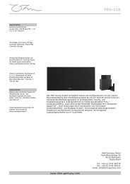
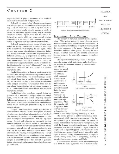
INPUT<br />
PRE-AMP PRE-EMPHASIS COMPRESSOR<br />
(AND LIMITER)<br />
TRANSMITTER: AUDIO CIRCUITRY<br />
The first part <strong>of</strong> the typical transmitter is the input circuitry.<br />
This section makes the proper electrical match<br />
between the input source <strong>and</strong> the rest <strong>of</strong> the transmitter. It<br />
must h<strong>and</strong>le the expected range <strong>of</strong> input levels <strong>and</strong> present<br />
the correct impedance to the source. Gain controls <strong>and</strong><br />
impedance switches allow greater flexibility in some<br />
designs. In certain cases, the input circuitry also provides<br />
electrical power to the source (for condenser microphone<br />
elements).<br />
The signal from the input stage passes to the signal<br />
processing section which optimizes the audio signal in several<br />
ways for the constraints imposed by radio transmission.<br />
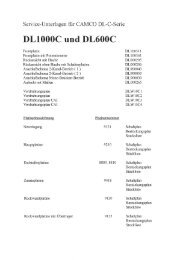
The first<br />
process is a special<br />
equalization called<br />
pre-emphasis,<br />
which is designed<br />
to minimize the<br />
apparent level <strong>of</strong><br />
high frequency<br />
noise (hiss) that is<br />
unavoidably added<br />
during the transmission.<br />
The<br />
“emphasis” is a<br />
specifically tailored<br />
boost <strong>of</strong> the high<br />
frequencies. When<br />
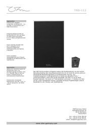
this is coupled with<br />
an equal (but opposite)<br />
“de-emphasis”<br />
in the receiver, the<br />
AF<br />
CRYSTAL<br />
VCO<br />
MULTIPLIERS<br />
effect is to reduce high frequency noise by up to 10 dB.<br />
The second process is called “comp<strong>and</strong>ing” (compress/exp<strong>and</strong>),<br />
which is designed to compensate for the limited<br />
dynamic range <strong>of</strong> radio transmission. The part <strong>of</strong> the<br />
process performed in the transmitter is “compression,” in<br />
which the dynamic range <strong>of</strong> the audio signal is reduced or<br />
compressed, typically by a factor <strong>of</strong> 2:1. Again, when this is<br />
coupled with an equal but opposite (1:2) “expansion” <strong>of</strong> the<br />
signal in the receiver, the original dynamic range <strong>of</strong> the audio<br />
signal is restored. Nearly all current wireless microphone<br />
systems employ some form <strong>of</strong> comp<strong>and</strong>ing, allowing a<br />
potential dynamic range greater than 100 dB.<br />
A refinement that is found in a few comp<strong>and</strong>er designs<br />
is to divide the audio signal into two or more frequency<br />
BASE<br />
RF<br />
Figure 9: crystal-controlled transmitter block diagram<br />
AF<br />
Input<br />
Level<br />
AF<br />
Output<br />
Level<br />
low<br />
frequencies<br />
unchanged<br />
Frequency<br />
high<br />
frequencies<br />
boosted<br />
RF AMP<br />
FINAL<br />
RF<br />
Figure 10a: pre-emphasis in transmitter<br />
low<br />
frequencies<br />
unchanged<br />
high<br />
frequencies (<strong>and</strong> noise)<br />
reduced<br />
Frequency<br />
Figure 10b: de-emphasis in transmitter<br />
SELECTION<br />
<strong>and</strong><br />
OPERATION OF<br />
WIRELESS<br />
MICROPHONE<br />
SYSTEMS