Installation Instructions zelsius C5 CMF - Zenner
Installation Instructions zelsius C5 CMF - Zenner
Installation Instructions zelsius C5 CMF - Zenner

Create successful ePaper yourself
Turn your PDF publications into a flip-book with our unique Google optimized e-Paper software.
EnergyMetering<br />
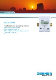
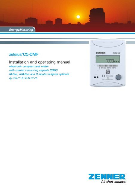
<strong>zelsius</strong> ® <strong>C5</strong>-<strong>CMF</strong><br />
<strong>Installation</strong> and operating manual<br />
electronic compact heat meter<br />
with coaxial measuring capsule (<strong>CMF</strong>)<br />
M-Bus, wM-Bus and 3 inputs/outputs optional<br />
qp 0,6/1,5/2,5 m 3 /h<br />
All that counts.
<strong>Installation</strong> manual<br />
General information<br />
With <strong>zelsius</strong> ® <strong>C5</strong>-<strong>CMF</strong> you have acquired one<br />
of the most up-to-date, modern heat meters currently<br />
available on the market.<br />
Expressive symbols in the display and easy<br />
menu navigation make readout simple. Can be<br />
operated with one single button. It is equipped<br />
with a long-life battery made for operation during<br />
the initial verification validity period (5 years) including<br />
a reserve of at least another year. The<br />
meter can be equipped optionally with a battery<br />
lifetime of 11 years.<br />
MID - Initial verification<br />
<strong>zelsius</strong> ® <strong>C5</strong>-<strong>CMF</strong> is produced and tested in<br />
compliance with the new European measuring<br />
instruments directive (MID). According to this<br />
directive, devices are no longer carrying an initial<br />
verification stamp, but rather the year of the<br />
device’s declaration of conformity (recognizable<br />
on the front of the device, for example: M12).<br />
The MID controls the use of heat meters up to<br />
the moment they are placed on the market resp.<br />
their first putting into use. After this, the national<br />
regulations for devices subject to compulsory verification<br />
apply within the EU.<br />
The duration of initial verification validity in Germany<br />
remains 5 years for heat meters. After this<br />
period has expired the measuring device may<br />
no longer be used for billing in commercial use.<br />
The regulations resp. validity period may vary in<br />
other countries of the EU. ZENNER International<br />
GmbH & Co. KG declares that this product<br />
with the number of the EC type-examination certificate<br />
DE-12-MI004-PTB010 complies with the<br />
requirements of the EC directives 2004/22/EC<br />
(Measuring instruments directive) and 89/336/<br />
EEC (electro-magnetic compatibility).<br />
Electro-magnetic interference<br />
<strong>zelsius</strong> ® <strong>C5</strong>-<strong>CMF</strong> fulfils the national and international<br />
requirements for interference resistance.<br />
To avoid malfunctions due to other interferences,<br />
do not install fluorescent lamps, switch<br />
cabinets or electric devices such as motors or<br />
pumps in the immediate vicinity of the meter (minimum<br />
distance 1 m). Cables leaving the meter<br />
should not be laid parallel to live cables (230V)<br />
(minimum distance 0.2 m).<br />
Care instructions<br />
Clean plastic surfaces with a damp cloth only.<br />
Do not use any scouring or aggressive cleaning<br />
agents! The device is maintenance-free during<br />
the service life. Repairs can only be made by the<br />
manufacturer.<br />
The most up-to-date information about this product<br />
and of our installation notice can be found at<br />
www.zenner.com<br />
2
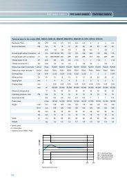
Technical data flow sensor <strong>CMF</strong> (Values for symmetrical temperature sensors installation)<br />
Nominal flow qp m³/h 0,6 1,5 2,5<br />
Maximum flow qs m³/h 1,2 3,0 5,0<br />
Minimum flow qi horizontally l / h 24 30 / 60 50 / 100<br />
Minimum flow qi vertically l / h 24 30 / 60 50 / 100<br />
Starting flow horizontally ca. l/h 5 5 7<br />
Pressure loss at qp bar
Technical data calculator<br />
Temperature range °C 0…105<br />
Temperature difference range K 3…80<br />
Display LCD 8-digit + additional character<br />
Ambient temperature °C 5...55<br />
Minimum temperature diffence K 3<br />
Resolution temperature °C 0,01<br />
Measurement frequency s adjustable ex works beginning with 2s, standard 30s<br />
Unit to read the heat consumption<br />
Data storage<br />
Due date values<br />
Maximum value storage<br />
Standard MWh; optionally kWh, GJ<br />
1 x daily<br />
Storage of all monthly values during the entire operating time<br />
extensive storage of flow rate, performance and other parameters<br />
Interface Standard optical interface (ZVEI, IrDA)<br />
optional<br />
M-Bus, wM-Bus, RS485, radio<br />
Supply<br />
3,6 V lithium battery (different capacities)<br />
Battery lifetime years > 6, opt. > 11 (changeable during the operating time)<br />
Protection class<br />
EMC<br />
Ambient conditions /<br />
climatic influencing<br />
(valid for complete compact meter)<br />
- climatic<br />
- mechanical<br />
class<br />
- electromagnetic<br />
class<br />
IP54<br />
C<br />
Highest permissible ambient temperature 55°C<br />
Lowest permissible ambient temperature 5°C<br />
Humidity class IP54<br />
M1<br />
E1<br />
4
Pulse inputs and outputs (optional)<br />
By meters with pulse inputs, the pulse value can be called up in the display (see the display overview,<br />
Level 4).<br />
The pulse value of the outputs is permanently set and corresponds with the last position of the associated<br />
display value.<br />
Example:<br />
Output 1 = energy output<br />
Energy display = XXXXX.XXX<br />
Last position = 0.001 MWh = 1 kWh<br />
Output pulse = 1 KWh<br />
In 1…3 Out 1…3<br />
Eingang<br />
In 1…3 Out 1…3<br />
GND<br />
Technical data I/O<br />
Load max<br />
max. 30V DC/20 mA<br />
I/O 1, 2, 3<br />
Open Drain, n-channel FET<br />
Cable<br />
D = 3.8 mm, 4-core<br />
Pulse-duty factor 1:1 (out); 1:5 (in)<br />
Cable length<br />
Input frequency<br />
Ausgang<br />
GND<br />
1,5 m<br />
max. 1 Hz<br />
A firmly attached cable is included: external<br />
wiring must be done by oneself.<br />
Eingang<br />
GND<br />
Ausgang<br />
GND<br />
Colour connection signification<br />
white I/O 1 In-/Output 1<br />
yellow I/O 2 In-/Output 2<br />
green I/O 3 In-/Output 3<br />
brown GND<br />
common ground for<br />
I/O 1-3<br />
M-Bus (optional)<br />
The optional M-Bus interface complies with the<br />
norm 1434-3 and operates with 2400 baud fixed.<br />
The two conductors can be connected in any<br />
order to the M-Bus network.<br />
Technical data M-Bus<br />
Cable length<br />
Cable<br />
1,5 m<br />
D=3.8m, 2-core<br />
colour connection signification<br />
brown M-Bus 1 M-Bus-Line 1<br />
white M-Bus 2 M-Bus-Line 2<br />
5
Dimensions<br />
Height compact version:<br />
Height combiversion (H1+H2):<br />
H = 50 mm<br />
H = 65 mm<br />
compact version<br />
Connecting sizes<br />
Nominal flow qp m³/h 0,6 1,5 2,5<br />
Nominal diameter DN mm 15 15 20<br />
Connecting length AS L mm 110 110 130<br />
Connecting pipe " ¾ ¾ 1<br />
(Measure X is depending from the used concentric flow meter (IST, M60, TE1)<br />
H1<br />
combiversion<br />
H2=25mm<br />
ZENNER International GmbH & Co. KG<br />
Römerstadt 6<br />
D-66121 Saarbrücken<br />
Telephone +49 681 99 676-30<br />
Telefax +49 681 99 676-3100<br />
E-Mail info@zenner.com<br />
Internet www.zenner.com<br />
Subject to modifications and errors excepted. Any liability for misprints excluded. SAP139725_130627_EN<br />
6
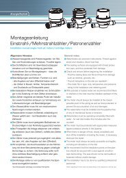
<strong>Installation</strong> instructions<br />
General information<br />
Read these instructions carefully right up to the<br />
end before starting to mount the device!<br />
The installation has to be done by qualified professional<br />
personnel. The current laws and regulations<br />
have to be observed, especially EN1434 part 1+6,<br />
(in Germany also AGFW directive FW202, FW510,<br />
FW218 and DIN4713 part 4 and the initial verification<br />
directive). At devices with M-Bus the general<br />
rules of technology and the respective regulations<br />
for electrical installations have to be followed.<br />
Make sure no heating water escapes during installation<br />
– this can cause burns!<br />
The maximum heating water temperature at the<br />
flow sensor may not exceed 90ºC.<br />
For heating systems with a lack of temperature<br />
mixing resp. with temperature stratification a<br />
straight pipeline of min. 10xDN has to be provided<br />
upstream of the meter.<br />
It is important to ensure adequate system pressure<br />
to avoid cavitation.<br />
To mount the heat computer of the <strong>C5</strong>-<strong>CMF</strong> in combi<br />
version on the wall, the supplied mounting adapter<br />
has to be used. The review of the approval can<br />
be identified definitely in the display menu (Level 3)<br />
ZENNER recommends to use direct temperature<br />
measurement and not to use immersion sleeves.<br />
The measuring capsule-flow meter (<strong>CMF</strong>) can be<br />
set in optionally only with the connecting interface<br />
versions according to DIN EN 14154-2 listed in the<br />
technical data. Using of connection interfaces or<br />
adapting inserts.<br />
Notes to installation of the flow sensor (VMT)<br />
■■<br />
Mount ball valves up- and downstream of the<br />
VMT.<br />
■■<br />
Consider the correct installation point (supply or<br />
return). Normally this is the return pipe (cooler<br />
pipe at heating systems). Please note the type<br />
plate information.<br />
■■<br />
Consider the correct flow direction. This is indicated<br />
by an arrow on the side of the VMT.<br />
■■<br />
Using of flow direction modifier is not allowed!<br />
■■Install horizontally or vertically only, not tilted,<br />
inclined or overhead. <strong>Installation</strong> into horizontal<br />
or upstreaming or downstreaming pipelines.<br />
■■<br />
Do not install at highest point of piping to avoid<br />
air inside the flow sensor.<br />
■■<br />
Consider the dimensions of the heat meter. Centre<br />
distance between 2 EAS at least 135 mm.<br />
■■<br />
Keep about 1 meter distance between <strong>zelsius</strong> ®<br />
<strong>C5</strong>-<strong>CMF</strong> and electromagnetic sources of interference<br />
like switch cabinets, motors or pumps.<br />
Keep about 0.2 m distance to power cables.<br />
Keep min. 3 cm free mounting space around the<br />
device.<br />
Notes ball valves<br />
■■<br />
Mount ball valves up- and downstream of the<br />
meter.<br />
■■<br />
Mount a ball valve with bore M10x1 for direct<br />
sensors in the supply. This is required for the<br />
installation of the supply sensor.<br />
■■<br />
For symmetrical temperature sensor installation,<br />
mount an identical ball valve in the return.<br />
7
Mounting heating / cooling energy meter<br />
■■<br />
Flush the system thoroughly before installing the<br />
heating energy meter.<br />
■■<br />
Close valves and release pressure.<br />
■■<br />
Screw out the overflow cap (2) or the existing<br />
measuring capsule.<br />
■■<br />
Check the seal face and thread on the measuring<br />
capsule and the EAS for damage.<br />
■■<br />
Remove the old profile seal, clean the seal face<br />
and insert the new one (3) into the EAS (4) with<br />
the flat side up.<br />
■■<br />
Attention: insert only one profile seal! The O-ring<br />
on the meter’s filter must be fitted into the groove.<br />
Use only new and flawless sealing material.<br />
■■<br />
Use only new and flawless sealing material.<br />
■■<br />
Remove the protective cap (1) from the new<br />
measuring capsule (5) and then screw into the<br />
EAS (4).<br />
■■<br />
Tighten measuring capsule up to the metallic stop<br />
with a hook wrench (for example: according to<br />
DIN 1810 A, 68-75 mm).<br />
■■<br />
Turn heat calculator to desired reading position.<br />
Information: The best measuring results can be<br />
achieved by mounting with horizontal diallevel.<br />
Combi-devices are, for example, used in tight installation<br />
points without room for the calculator on the<br />
flow sensor or when the calculator is difficult to read.<br />
Installing the temperature sensor<br />
■■<br />
The installation of the temperature sensors should<br />
be preferably symmetrical and direct installation.<br />
■■<br />
Do not remove the return sensor if already mounted<br />
in the VMU.This is also valid for all the safety<br />
seals which are mounted on the device as standard.<br />
■■<br />
Sensors are colour-coded (red = supply, blue =<br />
return).<br />
■■<br />
The connecting cables may not be buckled, extended<br />
or shortened.<br />
■■<br />
The seal at the sensor installation point on the<br />
measuring capsule may not be damaged.<br />
■■<br />
Remove locking screw and seal at the ball valve<br />
completely, if existing.<br />
■■<br />
Attach the O-ring to the installation aid (the 2nd<br />
O-ring is only a spare O-ring). Using the installation<br />
aid, insert the O-ring into the installation point<br />
according to DIN EN 1434 with a slight circular<br />
motion.<br />
■■<br />
Using the other end of the installation aid, bring<br />
the O-ring into the correct position.<br />
■■<br />
Insert the 2 halves of the plastic connector into the<br />
sensor’s three notches (crimps) and press them<br />
together.<br />
■■<br />
Use the installation aid as positioning aid.<br />
5)<br />
1)<br />
2)<br />
3)<br />
4)<br />
8
■■<br />
Insert the temperature sensor into the installation<br />
point and screw it in tightly until the dead stop of<br />
the seal on the 12-point is reached (mounting<br />
torque 3-5 Nm).<br />
■■<br />
The sensor optional integrated in the VMT has to<br />
be secured.<br />
■■<br />
Secure the sensor after installation against unauthorised<br />
removal with appropriate sealing (available<br />
as a sealing set)!<br />
Putting into use<br />
■■<br />
Open valves carefully and check installation for<br />
leakage.<br />
■■<br />
If the sleep mode of the counter is enabled (Display:<br />
SLEEP 1), then it must be deactivated by<br />
longer pressing the button (>5s).<br />
■■<br />
While the system is operating, check whether the<br />
volume display advances and the temperatures<br />
displayed correspond with the actual temperatures<br />
(see the display overview).<br />
■■<br />
Wait for the temperature display to be updated<br />
(1-2 sec).<br />
■■<br />
Secure the measuring capsule and the EAS with<br />
the enclosed sealing material against unauthorised<br />
removal.<br />
■■<br />
Fill in the putting into use report in accordance<br />
with PTB-Directive TR K9.<br />
Note relating to the mounting in existing<br />
immersion sleeves:<br />
The device <strong>C5</strong> can be put into use in connection<br />
with with existing immersion sleeves in accordance<br />
with the article “Putting in to use of MID homologated<br />
temperature sensors” released in the PTB<br />
notifications 119 (2009), vol.6. Based on current<br />
Montage DF- Adapter<br />
Supply<br />
Supply<br />
Return<br />
Load<br />
Return<br />
Asymmetric sensor installation for <strong>zelsius</strong> ® with the return sensor<br />
integrated in the flow sensor<br />
Supply<br />
Supply<br />
Return<br />
Return<br />
Asymmetric sensor installation for <strong>zelsius</strong> ® with the return sensor<br />
integrated in the flow sensor<br />
Symmetric sensor installation for <strong>zelsius</strong> ®<br />
Symmetric sensor installation for <strong>zelsius</strong> ®<br />
Load<br />
Load<br />
Load<br />
information, the regulation has a period of validity<br />
until 30.10.2016. For the identification and marking<br />
of the usable in existing immersion sleeves in<br />
connection with the <strong>C5</strong> device, an identification and<br />
marking set can be delivered from our company.<br />
9
Status display / Error codes<br />
The symbols in the table below show the meter’s operational status. The status messages only appear<br />
in the main display (energy)! The temporary display of the warning triangle can be caused by special<br />
operating states and does not always mean that the device is malfunctioning. However, should the<br />
symbol be displayed over a longer period of time you should contact the service company.<br />
Symbol Status Event<br />
External voltage -<br />
Flow existent -<br />
Attention!<br />
Check system / device for errors<br />
Symbol flashing: Data transmission -<br />
Symbol constantly displayed: optical interface active -<br />
Emergency operation<br />
Exchange device<br />
Error codes show faults detected by <strong>zelsius</strong> ® <strong>C5</strong>-ISF. If more than one error appears, the sum of the<br />
error codes is displayed: Error 1005 = error 1000 and error 5.<br />
Code Error Event<br />
1 Temperature out of measuring range Check sensors<br />
2 Temperature out of measuring range Check sensors<br />
3 Short-circuit return sensor Check sensors<br />
4 Interruption return sensor Check sensors<br />
5 Short-circuit supply sensor Check sensors<br />
6 Interruption supply sensor Check sensors<br />
7 Battery voltage Exchange device<br />
8 Hardware error Exchange device<br />
9 Hardware error Exchange device<br />
100 Hardware error Exchange device<br />
800 Wireless interface Exchange device<br />
1000 Status end of the battery Exchange device respectively battery*<br />
2000 Status Initial verification expired Exchange device<br />
* Due to certification reasons, change of the battery only possible abroad.<br />
10
1<br />
1<br />
1<br />
2<br />
3<br />
4<br />
1<br />
1<br />
1<br />
1<br />
1<br />
2<br />
3<br />
4<br />
1<br />
1<br />
2<br />
2<br />
2<br />
2<br />
2<br />
2<br />
2<br />
2<br />
2<br />
2<br />
2<br />
2<br />
2<br />
2<br />
2<br />
2<br />
2<br />
2<br />
2<br />
2<br />
3<br />
3<br />
2<br />
3<br />
3<br />
3<br />
3<br />
3<br />
3<br />
3<br />
3<br />
3<br />
3<br />
3<br />
3<br />
3<br />
3<br />
2<br />
3<br />
3<br />
3<br />
3<br />
3<br />
3<br />
3<br />
3<br />
3<br />
3<br />
3<br />
3<br />
4<br />
4<br />
4<br />
4<br />
4<br />
4<br />
Level 1 Level 2<br />
Important Note:<br />
Ebene Ebene 1 1 Ebene Ebene 2 2 Ebene Ebene 3 3 Ebene Ebene 4 4<br />
H H<br />
H H<br />
Heat energy Heat energy<br />
Heat energy Heat energy difference difference from from<br />
(Main (Main display) display)<br />
last due last date due to date nowto now<br />
The optical interface has to be activated by means<br />
of the OptoHead H H<br />
1through 1 keypress H H before<br />
Sensor type and<br />
reading out of the device.<br />
Sensor type and<br />
installation installation point VMT point VMT<br />
3<br />
3<br />
Pulse Pulse value value<br />
Input Input 1 1<br />
Ebenenwechse<br />
jedem jedem beliebig<br />
punkt punkt heraus hee<br />
Cooling Cooling energy energy<br />
Segment Segment test test<br />
Date last Date due last date due date<br />
Energy Energy<br />
Last due Last date due date<br />
Due date Due cooling date cooling energy energy<br />
Volume Volume<br />
Cooling Cooling energy energy difference difference<br />
from last from due last date due to date nowto now<br />
Heat energy Heat energy difference difference from from<br />
1. this 1. month this month to nowto now<br />
Cooling Cooling energy energy difference difference from from<br />
1. this 1. month this month to nowto now<br />
Volume Volume difference difference from from<br />
1. this 1. month this month to nowto now<br />
Maximal Maximal Flow Flow<br />
Date month Date month maximal maximal<br />
flow flow<br />
Devices,<br />
Serial number<br />
which are in Pulse sleep Pulse value valuemode (Display:<br />
Serial number<br />
SLEEP 1) have to be activated through keypress<br />
until Model number the energy display Pulse shows Pulse value value up.<br />
Model number<br />
Depending End of the battery on you meter’s model its displays<br />
End of the battery<br />
can differ in number and order from those shown<br />
here.<br />
Error Error status status<br />
S<br />
System System Date Date<br />
System System Time Time<br />
1<br />
3<br />
Input Input 2 2<br />
1<br />
3<br />
1<br />
3<br />
1<br />
3<br />
Input Input 3 3<br />
S<br />
S<br />
Legende Legende<br />
STaste Taste kurz kurz drücken drücken (S), zum (S), zum<br />
Blättern Blättern von oben von oben nach nach unten.<br />
Nach ten. Nach unterstem unterstem Menü-<br />
Menü-<br />
unpunkpunkt<br />
erfolgt erfolgt ein automatischescher<br />
Sprung Sprung zum zum obersten<br />
ein automati-<br />
obersten<br />
Menüpunkt Menüpunkt (Schleife). (Schleife).<br />
Flow rate Flow rate<br />
Supply Supply temperature temperature<br />
Return Return temperature temperature<br />
Maximum Maximum power, power, Average Average value value<br />
since since commissioning<br />
Maximum Maximum heat energy heat energy<br />
power power month month<br />
Maximum Maximum cooling cooling energy energy power, power,<br />
average average value value since since commissioning<br />
Operation Operation hours hours<br />
Primary Primary M-Bus M-Bus address address<br />
Certification Certification model model<br />
L<br />
Taste Taste etwa etwa 2 sec. 2 sec. drücken drücken<br />
L<br />
(L), (L), warten warten bis Türsymbol bis Türsymbol<br />
(oben (oben rechts rechts in der in Anzeige) der Anzeige)<br />
erscheint, erscheint, dann dann Taste Taste loslassensen.<br />
Erst Erst dann dann wird wird Menü<br />
loslas-<br />
Menü<br />
aktualisiert aktualisiert bzw. bzw. erfolgt erfolgt der der<br />
Sprung Sprung zum Untermenü.<br />
zum Untermenü.<br />
Temperature Temperature difference difference<br />
Maximum Maximum cooling cooling energy energy<br />
power power month month<br />
Firmware Firmware version version<br />
H<br />
Taste Taste halten halten (H) bis (H) Ebenenwechsewechsel<br />
oder oder Rück Rück sprung sprung<br />
bis Ebenen-<br />
H<br />
aus aus Untermenüs erfolgt. erfolgt.<br />
S<br />
S<br />
Current Current output output<br />
S S<br />
Function Function<br />
Output Output 1 1<br />
Function Function<br />
Output Output 2 2<br />
Hinweis Hinweis<br />
Je nach Je nach Ausführung Ausführung Ihres Ihres Zählers Zählers können können Anzeigen<br />
Reihenfolge Reihenfolge von den von den Abbildungen mehr mehr oder oder wenige w<br />
Function Function<br />
Output Output 3 3<br />
Opto readout Opto readout energy energy<br />
S<br />
S<br />
11
3<br />
3<br />
2<br />
3<br />
3<br />
3<br />
3<br />
3<br />
3<br />
3<br />
3<br />
3<br />
3<br />
3<br />
3<br />
3<br />
3<br />
2<br />
3<br />
3<br />
3<br />
3<br />
3<br />
3<br />
3<br />
3<br />
3<br />
3<br />
3<br />
3<br />
4<br />
4<br />
4<br />
4<br />
4<br />
4<br />
om<br />
om<br />
Level 3<br />
Level 4<br />
Ebene Ebene 3 3 Ebene Ebene 4 4<br />
H H<br />
Sensor Sensor type and type and<br />
Pulse Pulse value value<br />
installation installation point point VMT VMT<br />
Input Input 1 1<br />
Serial Serial number number<br />
Pulse Pulse value value<br />
Input Input 2 2<br />
Model Model number number<br />
Pulse Pulse value value<br />
Input Input 3 3<br />
1<br />
3<br />
1<br />
3<br />
1<br />
3<br />
1<br />
3<br />
1<br />
3<br />
1<br />
3<br />
H<br />
H<br />
Ebenenwechsel können können S<br />
jedem jedem beliebigen beliebigen Menüpunkpunkt<br />
heraus heraus erfolgen.<br />
Menü-<br />
erfolgen.<br />
Legend<br />
Press the button briefly (S)<br />
to switch through the display<br />
from top to bottom. When you<br />
have reached the last menu<br />
item the device automatically<br />
jumps back to the menu item<br />
at the top (loop).<br />
from<br />
e value<br />
power,<br />
missioning<br />
End of End the of battery the battery<br />
Error Error status status<br />
System System Date Date<br />
System System Time Time<br />
Operation Operation hours hours<br />
Primary Primary M-Bus M-Bus address address<br />
Certification Certification model model<br />
Firmware Firmware version version<br />
Function Function<br />
Output Output 1 1<br />
Function Function<br />
Output Output 2 2<br />
S S<br />
L<br />
Legende Legende<br />
S STaste Taste kurz kurz drücken drücken (S), zum (S), zum<br />
Blättern Blättern von oben von oben nach nach untenten.<br />
Nach Nach unterstem unterstem Menü-<br />
Menü-<br />
unpunkpunkt<br />
erfolgt erfolgt ein automatischescher<br />
Sprung Sprung zum zum obersten obersten<br />
ein automati-<br />
Menüpunkt Menüpunkt (Schleife). (Schleife).<br />
Taste Taste etwa etwa 2 sec. 2 sec. drücken drücken<br />
H<br />
L L<br />
(L), (L), warten warten bis Türsymbol bis Türsymbol<br />
(oben (oben rechts rechts in der in Anzeige) der Anzeige)<br />
erscheint, erscheint, dann dann Taste Taste loslassensen.<br />
Erst Erst dann dann wird wird Menü Menü<br />
loslas-<br />
aktualisiert aktualisiert bzw. bzw. erfolgt erfolgt der der<br />
Sprung Sprung zum zum Untermenü.<br />
Taste Taste halten halten (H) bis (H) Ebenenwechsewechsel<br />
oder oder Rück Rück sprung sprung<br />
bis Ebenen-<br />
H H<br />
aus aus Untermenüs erfolgt. erfolgt.<br />
Hinweis Hinweis<br />
Je nach Je nach Ausführung Ausführung Ihres Ihres Zählers Zählers können können Anzeigen Anzeigen in Anzahl in Anzahl und und<br />
Reihenfolge von den von den Abbildungen mehr mehr oder oder weniger weniger abweichen. abweichen.<br />
Press the button for about 2<br />
seconds (L), wait for the door<br />
symbol to appear (upper right<br />
corner of the display) and<br />
then release the button. The<br />
menu is then updated resp.<br />
switches to the sub-menu.<br />
Hold down the button (H)<br />
until the device switches to<br />
another level or switches<br />
back from the sub-menu.<br />
A detailed display overview<br />
including submenus is available<br />
upon request.<br />
Function Function<br />
Output Output 3 3<br />
Opto Opto readout readout energy energy<br />
S<br />
S<br />
12