Download in pdf format - Computer Vision Lab - ETH Zürich
Download in pdf format - Computer Vision Lab - ETH Zürich
Download in pdf format - Computer Vision Lab - ETH Zürich

You also want an ePaper? Increase the reach of your titles
YUMPU automatically turns print PDFs into web optimized ePapers that Google loves.
AWEAR 2.0 System: Omni-directional<br />
Audio-Visual Data Acquisition and Process<strong>in</strong>g<br />
Michal Havlena 1 Andreas Ess 2 Wim Moreau 3<br />
Akihiko Torii 1 Michal Jančošek 1 TomášPajdla 1 Luc Van Gool 2,3<br />
1 Center for Mach<strong>in</strong>e Perception, Department of Cybernetics<br />
Faculty of Elec. Eng., Czech Technical University <strong>in</strong> Prague<br />
{havlem1,torii,jancom1,pajdla}@cmp.felk.cvut.cz<br />
2 <strong>Computer</strong> <strong>Vision</strong> <strong>Lab</strong>oratory, D-ITET<br />
<strong>ETH</strong> <strong>Zürich</strong>, Switzerland<br />
{aess,vangool}@vision.ee.ethz.ch<br />
3 PSI-VISICS, ESAT<br />
KU Leuven, Belgium<br />
{Wim.Moreau,Luc.Vangool}@esat.kuleuven.be<br />
Abstract<br />
We present a wearable audio-visual captur<strong>in</strong>g system,<br />
termed AWEAR 2.0, along with its underly<strong>in</strong>g vision components<br />
that allow robust self-localization, multi-body pedestrian<br />
track<strong>in</strong>g, and dense scene reconstruction. Designed as<br />
a backpack, the system is aimed at support<strong>in</strong>g the cognitive<br />
abilities of the wearer. In this paper, we focus on the design<br />
issues for the hardware platform and on the performance of<br />
the current state-of-the-art computer vision methods on the<br />
acquired sequences. We describe the calibration procedure<br />
of the two omni-directional cameras present <strong>in</strong> the system<br />
as well as a Structure-from-Motion pipel<strong>in</strong>e that allows for<br />
stable multi-body track<strong>in</strong>g even from rather shaky video sequences<br />
thanks to ground plane stabilization. Furthermore,<br />
we show how a dense scene reconstruction can be obta<strong>in</strong>ed<br />
from data acquired with the platform.<br />
(a)<br />
(b)<br />
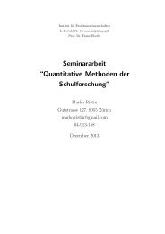
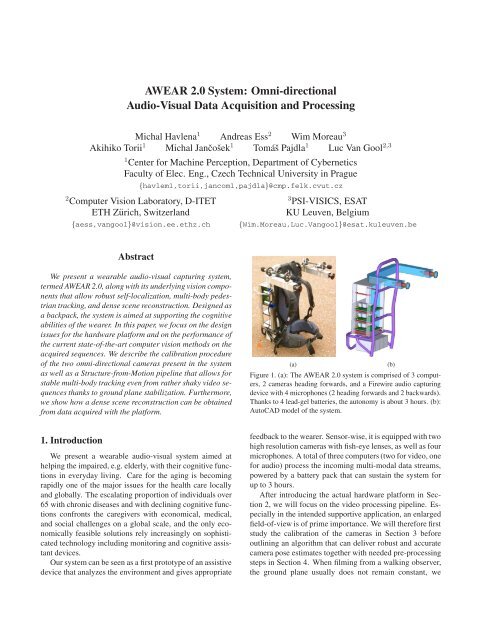
Figure 1. (a): The AWEAR 2.0 system is comprised of 3 computers,<br />
2 cameras head<strong>in</strong>g forwards, and a Firewire audio captur<strong>in</strong>g<br />
device with 4 microphones (2 head<strong>in</strong>g forwards and 2 backwards).<br />
Thanks to 4 lead-gel batteries, the autonomy is about 3 hours. (b):<br />
AutoCAD model of the system.<br />
1. Introduction<br />
We present a wearable audio-visual system aimed at<br />
help<strong>in</strong>g the impaired, e.g. elderly, with their cognitive functions<br />
<strong>in</strong> everyday liv<strong>in</strong>g. Care for the ag<strong>in</strong>g is becom<strong>in</strong>g<br />
rapidly one of the major issues for the health care locally<br />
and globally. The escalat<strong>in</strong>g proportion of <strong>in</strong>dividuals over<br />
65 with chronic diseases and with decl<strong>in</strong><strong>in</strong>g cognitive functions<br />
confronts the caregivers with economical, medical,<br />
and social challenges on a global scale, and the only economically<br />
feasible solutions rely <strong>in</strong>creas<strong>in</strong>gly on sophisticated<br />
technology <strong>in</strong>clud<strong>in</strong>g monitor<strong>in</strong>g and cognitive assistant<br />
devices.<br />
Our system can be seen as a first prototype of an assistive<br />
device that analyzes the environment and gives appropriate<br />
feedback to the wearer. Sensor-wise, it is equipped with two<br />
high resolution cameras with fish-eye lenses, as well as four<br />
microphones. A total of three computers (two for video, one<br />
for audio) process the <strong>in</strong>com<strong>in</strong>g multi-modal data streams,<br />
powered by a battery pack that can susta<strong>in</strong> the system for<br />
up to 3 hours.<br />
After <strong>in</strong>troduc<strong>in</strong>g the actual hardware platform <strong>in</strong> Section<br />
2, we will focus on the video process<strong>in</strong>g pipel<strong>in</strong>e. Especially<br />
<strong>in</strong> the <strong>in</strong>tended supportive application, an enlarged<br />
field-of-view is of prime importance. We will therefore first<br />
study the calibration of the cameras <strong>in</strong> Section 3 before<br />
outl<strong>in</strong><strong>in</strong>g an algorithm that can deliver robust and accurate<br />
camera pose estimates together with needed pre-process<strong>in</strong>g<br />
steps <strong>in</strong> Section 4. When film<strong>in</strong>g from a walk<strong>in</strong>g observer,<br />
the ground plane usually does not rema<strong>in</strong> constant, we
therefore propose a suitable stabilization approach. Based<br />
on this, we will show how to use the camera <strong>in</strong><strong>format</strong>ion<br />
together with a pedestrian detector to obta<strong>in</strong> multi-body<br />
track<strong>in</strong>g-by-detection and a dense 3D reconstruction of the<br />
scene <strong>in</strong> Section 5. The output of our system could then<br />
be used <strong>in</strong> further process<strong>in</strong>g stages to give cognitive feedback<br />
to the wearer. In its current embodiment, the wearable<br />
device is ma<strong>in</strong>ly used as a record<strong>in</strong>g platform. Our aim<br />
is to use the current state-of-the-art computer vision methods<br />
to process this type of image data <strong>in</strong> order to explore<br />
the potency and/or limits of egocentric vision, ma<strong>in</strong>ly <strong>in</strong> the<br />
means of construct<strong>in</strong>g an assistive device.<br />
The ma<strong>in</strong> benefits of the presented system are <strong>in</strong> particular<br />
(i) high resolution stereo, (ii) large field of view, and<br />
(iii) synchronization with multichannel high quality audio.<br />
When search<strong>in</strong>g for similar devices, one can f<strong>in</strong>d separate<br />
solutions, but not the comb<strong>in</strong>ation. Two experimental wearable<br />
devices closest to our platform are [13] and [14], both<br />
of them us<strong>in</strong>g just low resolution cameras and no audio.<br />
Exist<strong>in</strong>g commercial products offer<strong>in</strong>g broadcast<strong>in</strong>g quality<br />
are generally not wearable.<br />
The need for large field of view is demonstrated <strong>in</strong> [14],<br />
where two perspective cameras on each side of a walk<strong>in</strong>g<br />
person had to be used <strong>in</strong> order to cover the whole 360 ◦ horizontal<br />
field of view when solv<strong>in</strong>g a vision-based navigation<br />
task. Full resolution of the Po<strong>in</strong>tGrey Firefly MV cameras<br />
used was 752 × 480 pixels but as the system comprised of<br />
four Firewire-400 connected cameras, the frame rate could<br />
not go beyond 8fps due to bandwidth limitations.<br />
2. AWEAR 2.0 Acquisition Platform<br />
As AWEAR 2.0, shown <strong>in</strong> Figure 1, is constructed with<br />
the process<strong>in</strong>g of multi-modal data streams at high frame<br />
rates <strong>in</strong> m<strong>in</strong>d, the platform has to provide sufficient process<strong>in</strong>g<br />
power while keep<strong>in</strong>g both price and weight at acceptable<br />
levels. The constructed system comprises three computers,<br />
two for captur<strong>in</strong>g video and one for captur<strong>in</strong>g audio,<br />
the latter also act<strong>in</strong>g as the controller of the entire system.<br />
The system is powered by a battery pack that allows autonomous<br />
operation for up to 3 hours. On the sensor side,<br />
two cameras head<strong>in</strong>g forwards and a Firewire audio captur<strong>in</strong>g<br />
device with four microphones (two head<strong>in</strong>g forwards<br />
and two backwards) are used, triggered by a separate controller.<br />
All components, along with further support<strong>in</strong>g mechanic<br />
hardware, are mounted on a rigid frame. The weight<br />
of the presented system is around 25kg.<br />
2.1. Overview of the Major Components<br />
1. Video hardware<br />
• 2 video record<strong>in</strong>g computers, each with 2GB<br />
RAM, 570GB diskspace, and a Turion64 X2 TL-<br />
56 dual core processor<br />
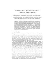
Figure 2. AWEAR 2.0 system consists of three computers, two<br />
Firewire-800 cameras connected via PCIe cards, four condenser<br />
microphones connected via a Firewire-400 audio captur<strong>in</strong>g device,<br />
and a power distribution logic with four batteries. A hardware<br />
trigger is used to synchronize cameras and the audio. Data l<strong>in</strong>ks<br />
are denoted by solid l<strong>in</strong>es, trigger l<strong>in</strong>ks by dashed l<strong>in</strong>es, and power<br />
l<strong>in</strong>ks by dotted l<strong>in</strong>es.<br />
• 2 AVT St<strong>in</strong>gray F-201C 2Mpixel 14fps color<br />
IEEE1394b video cameras produc<strong>in</strong>g 1624 ×<br />
1234 RAW images<br />
• 2 Fuj<strong>in</strong>on FE185CO86HA1 fish-eye lenses hav<strong>in</strong>g<br />
approximately 150 × 114 ◦ (H×V) FoV<br />
2. Audio hardware<br />
• 1 audio record<strong>in</strong>g computer with 1GB RAM,<br />
250GB diskspace, and a Mobile Sempron 2100+<br />
processor<br />
• 1 Focusrite Saffire Pro 10 I/O 10-channel 96kHz<br />
audio record<strong>in</strong>g device with microphone preamps<br />
and phantom power supplies<br />
• 4 T. Bone EM700 condenser microphones with<br />
freq. range 50–20,000Hz and sensitivity -42dB<br />
3. Trigger logic send<strong>in</strong>g a synchronization signal to both<br />
cameras and the soundcard<br />
4. Power dist. logic with 4 7.5Ah 12V lead-gel batteries<br />
5. Ethernet connection and wireless adapter<br />
6. Rigid frame backpack and other mechanic hardware<br />
S<strong>in</strong>ce not all the parameters were clearly known at design<br />
time, a modular design had been chosen. The platform<br />
can be extended to accommodate for four <strong>in</strong>stead of two<br />
cameras or have the cameras replaced with faster ones captur<strong>in</strong>g<br />
at double frame rate without hav<strong>in</strong>g to modify the<br />
comput<strong>in</strong>g platform itself. Furthermore, up to four additional<br />
microphones can be added by just plugg<strong>in</strong>g them <strong>in</strong>.<br />
The comput<strong>in</strong>g platform has marg<strong>in</strong> <strong>in</strong> both bandwidth and<br />
process<strong>in</strong>g power (see Figure 2).
(a)<br />
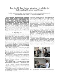
Figure 3. (a): AVT St<strong>in</strong>gray F-201C 2Mpixel 14fps color IEEE-<br />
1394b video camera produc<strong>in</strong>g 1624 × 1234 RAW images. Image<br />
courtesy of [1]. (b): Fuj<strong>in</strong>on FE185CO86HA1 fish-eye lens with<br />
approximately 150 × 114 ◦ (H×V) field of view. Image courtesy<br />
of [9].<br />
2.2. Video Hardware<br />
The video computers are two Siemens M<strong>in</strong>i-ITX <strong>in</strong>dustrial<br />
board computers D2703-S [25] with 2GB of RAM and<br />
2 SATA 2.5” harddisks of 250 and 320GB each. The processor<br />
is an AMD mobile Turion 64 X2 Dual Core TL-56<br />
which is equivalent to a dual core 1800MHz Intel processor.<br />
The ma<strong>in</strong> design difficulty <strong>in</strong> the record<strong>in</strong>g system is<br />
the bandwidth from the cameras to the disk on this mobile<br />
and hence relatively power-deprived system. As the bandwidth<br />
needed is 14fps × 1Byte/pixel × 1624 × 1234 pixels<br />
= 28MB/s for each camera, this has to be reflected <strong>in</strong><br />
most design choices. We chose 2 harddisks <strong>in</strong> order to double<br />
the bandwidth to them and to alleviate possible higher<br />
record<strong>in</strong>g rates (given appropriate cameras) or to <strong>in</strong>clude<br />
more cameras. SATA was chosen to <strong>in</strong>crease the <strong>in</strong>terface<br />
speed. Two 2.5” harddisks were preferred to one 3.5” harddisk<br />
(which typically has 1.5–2× higher bandwidth) for the<br />
weight and ma<strong>in</strong>ly for power consumption reasons.<br />
The cameras are Firewire-800 (IEEE-1394b), connected<br />
via a PCIe card to the ma<strong>in</strong>board. Firewire-400 would<br />
<strong>in</strong> pr<strong>in</strong>ciple suffice but would nearly entirely saturate both<br />
Firewire buses, as only 80% of 400Mbps is reserved for<br />
isochronous transport. Cameras used are AVT St<strong>in</strong>gray<br />
F-201C [1] cameras (see Figure 3(a)). Trigger<strong>in</strong>g is performed<br />
via hardware through a USB general purpose 32-bit<br />
IO device. The trigger command is issued by the control<br />
computer connected to this USB device.<br />
The employed lenses are Fuj<strong>in</strong>on FE185CO86HA1 [9]<br />
high-resolution fish-eye lenses (see Figure 3(b)) which yield<br />
a field of view of approximately 150 × 114 ◦ (H×V) on the<br />
2/3” CCD sensors of the cameras. The use of these highresolution<br />
lenses results <strong>in</strong> relatively m<strong>in</strong>or color aberration,<br />
so image data is free of artifacts across the entire field of<br />
view, and thus usable for process<strong>in</strong>g.<br />
2.3. Audio Hardware<br />
The audio and control computer is about the same as the<br />
video nodes except the—<strong>in</strong> comparison to video—limited<br />
process<strong>in</strong>g requirements which enable the use of a less pow-<br />
(b)<br />
(a)<br />
(b)<br />
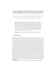
Figure 4. (a): Focusrite Saffire Pro 10 I/O 10-channel 96kHz audio<br />
record<strong>in</strong>g device with microphone pre-amps and phantom power<br />
supplies. Image courtesy of [8]. (b): T. Bone EM700 condenser<br />
microphones with range 50–20,000Hz and sensitivity -42dB. Image<br />
courtesy of [26].<br />
erful processor, an AMD mobile Sempron 2100+, us<strong>in</strong>g<br />
about 1/3 of the power of a video node under full load, thus<br />
<strong>in</strong>creas<strong>in</strong>g autonomy considerably. The audio record<strong>in</strong>g device,<br />
a Focusrite Saffire Pro 10 I/O [8] 10-channel 96kHz<br />
<strong>in</strong>terface with microphone pre-amps and phantom power<br />
supplies (see Figure 4(a)), is connected to this computer via<br />
the onboard Firewire-400 port.<br />
Microphones used are T. Bone EM700 [26] condenser<br />
microphones (see Figure 4(b)) with a frequency range of<br />
50–20,000Hz and a sensitivity of -42dB.<br />
2.4. Power Distribution Logic<br />
The computers’ onboard 24V DC power supply is connected<br />
to a power supply board which draws power from<br />
either the battery packs of 2×12V, 7.5Ah lead-gel batteries<br />
each, or an external power supply. Cameras are powered by<br />
the attached computer via the Firewire bus. The audio device<br />
is powered directly to the power board s<strong>in</strong>ce the ma<strong>in</strong>board<br />
could not supply enough power over Firewire. This is<br />
accomplished by connect<strong>in</strong>g the Firewire cable through the<br />
power board and us<strong>in</strong>g it as a power <strong>in</strong>serter.<br />
Under full load, the video computers draw 2.1A @ 24V<br />
each (with cameras operat<strong>in</strong>g), the audio computer 0.7A @<br />
24V (with USB trigger attached), and the audio <strong>in</strong>terface<br />
0.25–1A @ 24V, total<strong>in</strong>g at about 5.5A. The batteries supply<br />
15Ah @ 24+V, result<strong>in</strong>g <strong>in</strong> autonomy of slightly under<br />
3 hours under full load. In normal operation, the actual<br />
consumption of the computers is about 1.1A for video and<br />
0.35–0.5A for audio, result<strong>in</strong>g <strong>in</strong> a longer autonomy.<br />
2.5. Software & Control<br />
We use Ubuntu 8.10 as the operat<strong>in</strong>g system and several<br />
applications for video and audio capture. Video is captured<br />
<strong>in</strong> raw (bayered) <strong>format</strong> <strong>in</strong>to streams of 1000 files each, audio<br />
is saved as a 5-channel file, with the fifth channel conta<strong>in</strong><strong>in</strong>g<br />
the trigger pulse for video-audio synchronization.<br />
The control computer is connected to the other computers<br />
via gigabit-Ethernet, and wireless access allows the remote<br />
control of the entire system.
θ<br />
(a)<br />
r<br />
Figure 5. (a) Equi-angular projection model. (b) Calibration target<br />
used for fish-eye lens calibration.<br />
(b)<br />
(a)<br />
(b)<br />
Figure 6. (a) Sample RAW image from the camera. (b) Examples<br />
of debayered image data on two cutouts from the RAW image.<br />
3. AWEAR 2.0 Calibration<br />
In the follow<strong>in</strong>g sections, we will focus on the vision aspect<br />
and hence the video system of the AWEAR 2.0 platform.<br />
For a system aimed at cognitive support, fish-eye<br />
lenses are very helpful due to their extended field of view.<br />
As their handl<strong>in</strong>g requires some care, we will first describe<br />
the process of their calibration.<br />
Calibration of the lens reveals the trans<strong>format</strong>ion between<br />
the pixels <strong>in</strong> the omni-directional image and rays<br />
<strong>in</strong> 3D. As the lens model should be equi-angular (see Figure<br />
5(a)), we use a two-parameter model [19] which is an<br />
extension of the equi-angular model that allows to compensate<br />
for small defects of non-expensive lenses due to manufactur<strong>in</strong>g:<br />
θ =<br />
ar<br />
1+br 2 . (1)<br />
Due to aberrations dependent on manufactur<strong>in</strong>g and mount<strong>in</strong>g,<br />
it is necessary to calibrate both lenses. For calibration,<br />
the entire field of view should be covered by a calibration<br />
target, render<strong>in</strong>g standard planar calibration targets unusable.<br />
We thus chose a cube with a side length of 40cm as<br />
calibration target. It is covered by a checkerboard pattern,<br />
with some cells labeled with letters and symbols (see Figure<br />
5(b)). The top left corners of the labeled cells are selected<br />
manually, yield<strong>in</strong>g a total of up to 160 2D po<strong>in</strong>ts<br />
when the whole cube is visible. As the currently employed<br />
lens has a slightly smaller field of view, a part of the cube<br />
was not visible, but we could still measure more than 120<br />
po<strong>in</strong>ts.<br />
Based on the 2D po<strong>in</strong>ts’ correspond<strong>in</strong>g 3D po<strong>in</strong>ts, we<br />
optimize for the two parameters of the lens model along<br />
with the camera pr<strong>in</strong>cipal po<strong>in</strong>t and the unknown relative<br />
pose between the calibration object and the camera.<br />
In order to f<strong>in</strong>d the trans<strong>format</strong>ion between the left and<br />
the right camera, we recorded a short sequence of 808<br />
frames while walk<strong>in</strong>g <strong>in</strong> a room and then recovered the<br />
epipolar geometry as follows.<br />
In every 10th image pair a variety of features were detected,<br />
<strong>in</strong>clud<strong>in</strong>g MSER <strong>in</strong>tensity +/- [17] and Laplacian-<br />
Aff<strong>in</strong>e [20]. Tentative correspondences between the left and<br />
the right image were found <strong>in</strong>dependently for each stereo<br />
pair captured at the same time. F<strong>in</strong>ally, tentative correspondences<br />
from all pairs of images were concatenated and<br />
epipolar geometry was found us<strong>in</strong>g the previously obta<strong>in</strong>ed<br />
lens calibration us<strong>in</strong>g RANSAC with the 5-po<strong>in</strong>t relative<br />
pose algorithm [22] as hypothesis generator.<br />
To obta<strong>in</strong> a fully metric reconstruction, the real-world<br />
distance between the camera pair, <strong>in</strong> our case 45cm, needs<br />
to be applied to the found trans<strong>format</strong>ion.<br />
4. Low-level Visual Data Process<strong>in</strong>g<br />
In our vision system, we differ between two levels of<br />
visual data process<strong>in</strong>g. The lower level recovers camera positions<br />
for each stereo pair and provides the higher level, i.e.<br />
object detection and dense reconstruction, with appropriate<br />
images. Depend<strong>in</strong>g on the high level module, this can be<br />
stabilization of the image w.r.t. a ground plane, or perspective<br />
cutouts.<br />
4.1. De-Bayer<strong>in</strong>g<br />
As the cameras use only a s<strong>in</strong>gle CCD chip, the images<br />
first have to be debayered. For optimal results, we use an<br />
adaptive homogeneity-directed <strong>in</strong>terpolation method suggested<br />
by [12]. An additional gamma correction is used to<br />
make the images more amenable for feature detection (see<br />
Figure 6(b)).<br />
4.2. Cutout Generation<br />
Based on the lens calibration, we are able to generate<br />
perspective, cyl<strong>in</strong>drical, or any other projection model<br />
cutouts from the orig<strong>in</strong>al omni-directional images. A given<br />
omni-directional image can be mapped onto a surface of a<br />
unit sphere as the lens calibration transforms image pixel<br />
positions <strong>in</strong>to unit vectors (directions). This surface can be
(a)<br />
(b)<br />
(c)<br />
Figure 7. (a) Orig<strong>in</strong>al omni-directional image. (b) Non-central<br />
cyl<strong>in</strong>drical projection image. (c) 3 × 3 perspective cutouts. Notice<br />
the image overlap of the corner images with the other.<br />
then projected to any other surface us<strong>in</strong>g the desired projection<br />
model. Technically, we do <strong>in</strong>verse filter<strong>in</strong>g from the<br />
result<strong>in</strong>g image <strong>in</strong>to the source image, the f<strong>in</strong>al pixel value<br />
is obta<strong>in</strong>ed by bil<strong>in</strong>ear <strong>in</strong>terpolation.<br />
Non-central cyl<strong>in</strong>drical projection images. To generate<br />
images more suitable for object recognition while keep<strong>in</strong>g<br />
the full field of view, we use non-central cyl<strong>in</strong>drical projection<br />
[27], see Figure 7(b). Optionally, images can be<br />
stabilized dur<strong>in</strong>g the process us<strong>in</strong>g the estimated camera<br />
poses. This is especially helpful for fix<strong>in</strong>g the ground plane<br />
from shaky images, thus constra<strong>in</strong><strong>in</strong>g pedestrian detection<br />
to mean<strong>in</strong>gful locations. See Sections 4.3 and 4.4 for details.<br />
Perspective cutouts. Alternatively, we can also generate<br />
a group of n<strong>in</strong>e 600 × 600 perspective images with field of<br />
view 60 × 60 ◦ by project<strong>in</strong>g the surface of the sphere to<br />
its tangent planes <strong>in</strong> n<strong>in</strong>e different directions. First is the direction<br />
of the optical axis (z-axis), other directions are computed<br />
by rotat<strong>in</strong>g the optical axis around the x-axis (top and<br />
bottom images), the y-axis (left and right images), or both<br />
axes (corner images) by 60 degrees. Us<strong>in</strong>g these sett<strong>in</strong>gs,<br />
the result<strong>in</strong>g images cover the whole half sphere with image<br />
overlaps present <strong>in</strong> corner images only. If corner images are<br />
not used, there are no image overlaps present but some parts<br />
of the orig<strong>in</strong>al image are miss<strong>in</strong>g (see Figure 7(c)).<br />
4.3. Structure-from-Motion<br />
Structure-from-Motion (SfM) computation recovers the<br />
unknown camera poses needed for image stabilization,<br />
multi-body track<strong>in</strong>g, and dense 3D reconstruction. We will<br />
demonstrate the pose computation based on the <strong>in</strong>door sequence<br />
used above.<br />
Sequence OLDENBURG is 808 frames long and the distance<br />
between consecutive frames is 0–0.2 meters as it was<br />
Figure 8. Features detected on images from sequence OLDEN-<br />
BURG. MSER <strong>in</strong>t+ (red), MSER <strong>in</strong>t- (blue), MSER sat+ (magenta),<br />
MSER sat- (cyan), and SURF (yellow). Notice the lack<br />
of feature regions on the last image acquired <strong>in</strong> a difficult turn.<br />
captured at 10fps while stand<strong>in</strong>g still and walk<strong>in</strong>g <strong>in</strong>side a<br />
room. For comput<strong>in</strong>g the camera poses by SfM robustly,<br />
129 keyframes are selected us<strong>in</strong>g the algorithm described<br />
<strong>in</strong> [27]. This algorithm computes the dom<strong>in</strong>ant, i.e. the most<br />
frequent, apical angle, which is the angle under which the<br />
camera centers are seen from the perspective of the reconstructed<br />
scene po<strong>in</strong>ts [28]. A new keyframe is selected if<br />
the dom<strong>in</strong>ant apical angle between the current frame and<br />
the previously selected keyframe is greater than one degree.<br />
Otherwise, current frame is skipped and processed dur<strong>in</strong>g<br />
glu<strong>in</strong>g as described below.<br />
In brief, the computation proceeds <strong>in</strong> several steps:<br />
First, different aff<strong>in</strong>e covariant feature regions <strong>in</strong>clud<strong>in</strong>g<br />
MSER [17] and SURF [2] are detected <strong>in</strong> <strong>in</strong>put images (see<br />
Figure 8). The detected regions are assigned local aff<strong>in</strong>e<br />
frames (LAF) [23] and described by discrete cos<strong>in</strong>e descriptors<br />
[24]. Secondly, tentative feature region matches<br />
are constructed from mutually closest descriptors <strong>in</strong> the<br />
feature space us<strong>in</strong>g FLANN [21] which performs fast approximate<br />
nearest neighbour search based on a hierarchical<br />
k-means tree. The 5-po<strong>in</strong>t m<strong>in</strong>imal relative pose problem<br />
for calibrated cameras [22] is used for generat<strong>in</strong>g camera<br />
pose hypotheses and PROSAC [4], an ordered variant<br />
of RANSAC [7], together with vot<strong>in</strong>g similar to that used<br />
<strong>in</strong> [16] is used to f<strong>in</strong>d the largest subset of the set of tentative<br />
matches that is geometrically consistent. F<strong>in</strong>ally, <strong>in</strong>liers of<br />
the geometry test are triangulated <strong>in</strong>to 3D po<strong>in</strong>ts [11] and<br />
the dom<strong>in</strong>ant apical angle is measured. Obta<strong>in</strong>ed relative<br />
camera poses are cha<strong>in</strong>ed through the sequence result<strong>in</strong>g <strong>in</strong><br />
the absolute poses of all keyframe cameras.<br />
Us<strong>in</strong>g the recovered camera poses of the keyframe images,<br />
the camera poses of the rema<strong>in</strong><strong>in</strong>g images are computed<br />
by the technique of glu<strong>in</strong>g described also <strong>in</strong> [27]. If
Figure 9. Camera trajectory of sequence OLDENBURG. The<br />
bird’s eye view of the result<strong>in</strong>g 3D model. Small dots represent<br />
the reconstructed world 3D po<strong>in</strong>ts. Red cones represent the camera<br />
positions of the whole sequence <strong>in</strong>clud<strong>in</strong>g glued and <strong>in</strong>terpolated<br />
camera positions.<br />
the scene is difficult and glu<strong>in</strong>g fails for some cameras, their<br />
poses are obta<strong>in</strong>ed by <strong>in</strong>terpolation from neighbour<strong>in</strong>g cameras.<br />
Figure 9 shows the camera positions for the whole<br />
sequence and the recovered 3D po<strong>in</strong>ts.<br />
4.4. Image Stabilization<br />
The recovered camera poses and trajectory can be used<br />
to rectify the orig<strong>in</strong>al images to the stabilized ones. If there<br />
exists no assumption on the camera motion <strong>in</strong> a sequence,<br />
the simplest way of stabilization is to rectify images w.r.t.<br />
the gravity vector <strong>in</strong> the coord<strong>in</strong>ate system of the first camera<br />
and all other images will then be aligned with the first<br />
one. This can be achieved by tak<strong>in</strong>g the first image with<br />
care.<br />
For a gravity direction g and a motion direction t, we<br />
compute the normal vector of the ground plane:<br />
d =<br />
t × (g × t)<br />
|t × (g × t)| . (2)<br />
We construct the stabilization and rectification transform R s<br />
for the image po<strong>in</strong>t represented as a 3D unit vector such that<br />
R s =[a, d, b ] where<br />
a = (0, 0, 1)⊤ × d<br />
|(0, 0, 1) ⊤ (3)<br />
× d|<br />
and<br />
b = a × d<br />
|a × d| . (4)<br />
This formulation is sufficient because the pavements usually<br />
go up and down to the view direction.<br />
Figure 10 shows several frames of the orig<strong>in</strong>al images <strong>in</strong><br />
sequence OLDENBURG (a), the correspond<strong>in</strong>g panoramic<br />
images without camera stabilization (b), and the panoramic<br />
images stabilized w.r.t. the gravity vector <strong>in</strong> the coord<strong>in</strong>ate<br />
system of the first camera us<strong>in</strong>g the recovered camera poses<br />
and trajectory (c).<br />
(a) (b) (c)<br />
Figure 10. Result of our image stabilization and trans<strong>format</strong>ion <strong>in</strong><br />
sequence OLDENBURG. (a) Orig<strong>in</strong>al images. (b) Non-stabilized<br />
non-central cyl<strong>in</strong>drical projection images. (c) Stabilized images<br />
w.r.t. the gravity vector <strong>in</strong> the first camera coord<strong>in</strong>ates.<br />
5. Higher-level Visual Data Process<strong>in</strong>g<br />
Given the data preprocessed by the lower levels of the<br />
system, we can now apply higher-level visual data process<strong>in</strong>g.<br />
In this paper, we will give two examples of higher-level<br />
visual data process<strong>in</strong>g: multi-body track<strong>in</strong>g and dense 3D<br />
reconstruction.<br />
Both tasks are demonstrated on the sequence PED-<br />
CROSS. 228 frames long, it is taken while walk<strong>in</strong>g on a<br />
pavement and observ<strong>in</strong>g several pedestrians. The sequence<br />
is captured at 12fps, result<strong>in</strong>g <strong>in</strong> a distance of 0.05–0.15 meters<br />
between consecutive frames.<br />
10 keyframes were selected us<strong>in</strong>g the algorithm described<br />
<strong>in</strong> Section 4.3 <strong>in</strong> order to have a sufficient dom<strong>in</strong>ant<br />
apical angle. Us<strong>in</strong>g the recovered camera poses of<br />
the keyframe images, the rema<strong>in</strong><strong>in</strong>g camera poses are computed<br />
by glu<strong>in</strong>g. Figure 11 shows the camera positions for<br />
the whole sequence and the world 3D po<strong>in</strong>ts. Us<strong>in</strong>g the<br />
algorithms described above, we generate non-central cyl<strong>in</strong>drical<br />
projection images that are stabilized w.r.t. the gravity<br />
vector <strong>in</strong> the coord<strong>in</strong>ate system of the first camera.<br />
5.1. Multi-body Track<strong>in</strong>g-by-Detection<br />
The stabilized panoramic images form the basis for<br />
a track<strong>in</strong>g-by-detection approach that follows an earlier<br />
work [6]. In short, we detect pedestrian bound<strong>in</strong>g boxes us<strong>in</strong>g<br />
a state-of-the-art detector [5] and place these detections<br />
<strong>in</strong>to a common world coord<strong>in</strong>ate system us<strong>in</strong>g the known<br />
ground plane and the camera positions.<br />
The actual multi-body track<strong>in</strong>g system then follows a<br />
multi-hypotheses approach. For this, we accumulate the de-
Figure 11. Camera trajectory of sequence PEDCROSS and bird’s<br />
eye view of the result<strong>in</strong>g 3D model. Small dots represent the<br />
reconstructed world 3D po<strong>in</strong>ts. Red cones represent the camera<br />
positions of the whole sequence <strong>in</strong>clud<strong>in</strong>g glued and <strong>in</strong>terpolated<br />
camera positions.<br />
tections of the current and past frames <strong>in</strong> a space-time volume.<br />
This volume is analyzed by generat<strong>in</strong>g many trajectory<br />
hypotheses us<strong>in</strong>g <strong>in</strong>dependent bi-directional Extended<br />
Kalman filters (EKFs) with a constant-velocity model.<br />
To deal with data association uncerta<strong>in</strong>ties, we generate<br />
an overcomplete set of trajectories by start<strong>in</strong>g EKFs<br />
from detections at different time steps. The obta<strong>in</strong>ed set<br />
is then pruned to a m<strong>in</strong>imal consistent explanation us<strong>in</strong>g<br />
model selection. This step simultaneously resolves conflicts<br />
from overlapp<strong>in</strong>g trajectory hypotheses by lett<strong>in</strong>g trajectories<br />
compete for detections <strong>in</strong> the space-time volume. For<br />
the mathematical details, we refer to [15]. The most important<br />
features of this method are automatic track <strong>in</strong>itialization<br />
(usually, after about 5 detections) and the ability to recover<br />
from temporary track loss and occlusion.<br />
Figure 12 shows several frames of the sequence PED-<br />
CROSS before process<strong>in</strong>g (a), the panoramic images without<br />
camera stabilization (b), and the results of the multibody<br />
track<strong>in</strong>g [6] performed on the sequence of panoramic<br />
images stabilized us<strong>in</strong>g the recovered camera poses and trajectory<br />
(c).<br />
Obta<strong>in</strong>ed pedestrians and their tracks can be used as <strong>in</strong>put<br />
to even higher process<strong>in</strong>g levels, e.g. action recognition,<br />
which classifies pedestrians by their movement and detects<br />
pedestrians that behave unusually.<br />
5.2. Dense 3D Reconstruction<br />
Know<strong>in</strong>g the camera poses, one can reconstruct a dense<br />
3D model of the captured scene. We have used a Scalable<br />
Multi-View Stereo (SMVS) pipel<strong>in</strong>e which works with<br />
an unordered set of perspective images and correspond<strong>in</strong>g<br />
camera poses [27], therefore we had to convert the <strong>in</strong>put set<br />
of omni-directional images <strong>in</strong>to perspective cutouts us<strong>in</strong>g<br />
the method described <strong>in</strong> Section 4.2.<br />
Our work follows the reconstruction paradigm used <strong>in</strong><br />
previous works but modifies and improves <strong>in</strong>dividual components.<br />
We use approach similar [18], which can deal<br />
with large video sequences work<strong>in</strong>g with a few neighbour<strong>in</strong>g<br />
frames of each actual frame to compute and fuse the<br />
depth maps.<br />
(a) (b) (c)<br />
Figure 12. Results of our image stabilization and trans<strong>format</strong>ion<br />
<strong>in</strong> sequence PEDCROSS. (a) Orig<strong>in</strong>al images. (b) Non-stabilized<br />
non-central cyl<strong>in</strong>drical projection images. (c) Stabilized images<br />
w.r.t. the gravity vector <strong>in</strong> the first camera coord<strong>in</strong>ates together<br />
with pedestrian track<strong>in</strong>g.<br />
We build upon the work of [10]. In particular, we modify<br />
the reconstruction process to be scalable by accumulat<strong>in</strong>g<br />
reconstructed scene and avoid<strong>in</strong>g unnecessary computations<br />
and improve the filter<strong>in</strong>g step by us<strong>in</strong>g MRF filter<strong>in</strong>g<br />
formulation [3]. Four different views of the result<strong>in</strong>g<br />
VRML model are shown <strong>in</strong> Figure 13.<br />
The obta<strong>in</strong>ed result can be used for depth map generation,<br />
which can facilitate image segmentation and also allows<br />
for better understand<strong>in</strong>g of the scene geometry utilized<br />
by other higher process<strong>in</strong>g levels, e.g. obstacle detection<br />
warn<strong>in</strong>g the wearer from unwanted hits.<br />
6. Conclusions<br />
We have described a wearable audio-visual sensor platform<br />
that is aimed at cognitive supportive applications for<br />
the elderly. Both aspects of hardware and software were<br />
considered. For an enlarged field of view, cameras with fisheye<br />
lenses are used, putt<strong>in</strong>g special requirements on data<br />
process<strong>in</strong>g. To this end, we proposed low-level methods for<br />
calibration, projective mapp<strong>in</strong>g, SfM, and image stabilization<br />
from such data. Based on the robust output of these<br />
components, we demonstrated two high-level tasks, multibody<br />
pedestrian track<strong>in</strong>g and dense 3D reconstruction.<br />
In its current embodiment, we use the hardware platform<br />
as captur<strong>in</strong>g device only, with video stream process<strong>in</strong>g done<br />
off-l<strong>in</strong>e. While the low-level process<strong>in</strong>g steps are not far<br />
from real-time performance: debayer<strong>in</strong>g takes 1s per image,<br />
cutout generation 2s per image, and SfM with stabilization<br />
7s per image, higher-level process<strong>in</strong>g steps are slower:
Figure 13. Four different views of the f<strong>in</strong>al dense 3D reconstruction<br />
of sequence PEDCROSS with given camera positions and orientations<br />
(green).<br />
pedestrian detection takes 40s per image and dense 3D reconstruction<br />
60s per image.<br />
Future work will encompass br<strong>in</strong>g<strong>in</strong>g the algorithms up<br />
to speed to run on the platform. Then, additional higher<br />
level components can provide actual cognitive feedback to<br />
the wearer.<br />
Acknowledgements<br />
This work was supported by EC project FP6-IST-027787<br />
DIRAC and by Czech Science Foundation under Project<br />
201/07/1136. T. Pajdla was supported by Czech Government<br />
under the research program MSM6840770038. Any<br />
op<strong>in</strong>ions expressed <strong>in</strong> this paper do not necessarily reflect<br />
the views of the European Community. The Community is<br />
not liable for any use that may be made of the <strong>in</strong><strong>format</strong>ion<br />
conta<strong>in</strong>ed here<strong>in</strong>.<br />
References<br />
[1] AVT - St<strong>in</strong>gray. http: // www.alliedvisiontec.com / avtproducts<br />
/ cameras / st<strong>in</strong>gray / f-201-b-bs-c-fiber.html, 2008.<br />
[2] H. Bay, A. Ess, T. Tuytelaars, and L. Van Gool. Speeded-up<br />
robust features (SURF). CVIU, 110(3):346–359, June 2008.<br />
[3] N. Campbell, G. Vogiatzis, C. Hernandez, and R. Cipolla.<br />
Us<strong>in</strong>g multiple hypotheses to improve depth-maps for multiview<br />
stereo. In ECCV’08, 2008.<br />
[4] O. Chum and J. Matas. Match<strong>in</strong>g with PROSAC - progressive<br />
sample consensus. In CVPR’05, pages 220–226, 2005.<br />
[5] N. Dalal and B. Triggs. Histograms of oriented gradients for<br />
human detection. In CVPR’05, pages 886–893, 2005.<br />
[6] A. Ess, B. Leibe, K. Sch<strong>in</strong>dler, and L. Van Gool. A mobile<br />
vision system for robust multi-person track<strong>in</strong>g. In CVPR’08,<br />
2008.<br />
[7] M. Fischler and R. Bolles. Random sample consensus: A<br />
paradigm for model fitt<strong>in</strong>g with applications to image analysis<br />
and automated cartography. Comm. ACM, 24(6):381–<br />
395, June 1981.<br />
[8] Focusrite - Saffire. http: // www.focusrite.com / products /<br />
saffire / saffire pro 10 io /, 2008.<br />
[9] Fuj<strong>in</strong>on - FE185. http: // www.fuj<strong>in</strong>on.com / security / product.aspx<br />
cat=1019 & id=1072, 2008.<br />
[10] Y. Furukawa and J. Ponce. Accurate, dense, and robust multiview<br />
stereopsis. In CVPR’07, 2007.<br />
[11] R. Hartley and A. Zisserman. Multiple View Geometry <strong>in</strong><br />
<strong>Computer</strong> <strong>Vision</strong>. Cambridge University Press, second edition,<br />
2003.<br />
[12] K. Hirakawa and T. Parks. Adaptive homogeneity-directed<br />
demosaic<strong>in</strong>g algorithm. IP, 14(3):360–369, March 2005.<br />
[13] R. Kelly and R. Green. Camera egomotion track<strong>in</strong>g us<strong>in</strong>g<br />
markers. In IVCNZ’06, 2006.<br />
[14] O. Koch and S. Teller. A self-calibrat<strong>in</strong>g, vision-based navigation<br />
assistant. In CVAVI’08, 2008.<br />
[15] B. Leibe, K. Sch<strong>in</strong>dler, N. Cornelis, and L. Van Gool. Coupled<br />
object detection and track<strong>in</strong>g from static cameras and<br />
mov<strong>in</strong>g vehicles. PAMI, 30(10):1683–1698, October 2008.<br />
[16] H. Li and R. Hartley. A non-iterative method for correct<strong>in</strong>g<br />
lens distortion from n<strong>in</strong>e po<strong>in</strong>t correspondences. In OM-<br />
NIVIS’05, 2005.<br />
[17] J. Matas, O. Chum, M. Urban, and T. Pajdla. Robust wide<br />
basel<strong>in</strong>e stereo from maximally stable extremal regions. IVC,<br />
22(10):761–767, September 2004.<br />
[18] P. Merrell, A. Akbarzadeh, L. Wang, P. Mordohai, J. Frahm,<br />
R. Yang, D. Nister, and M. Pollefeys. Real-time visibilitybased<br />
fusion of depth maps. In ICCV’07, 2007.<br />
[19] B. Mičušík and T. Pajdla. Structure from motion with wide<br />
circular field of view cameras. PAMI, 28(7):1135–1149, July<br />
2006.<br />
[20] K. Mikolajczyk et al. A comparison of aff<strong>in</strong>e region detectors.<br />
IJCV, 65(1-2):43–72, 2005.<br />
[21] M. Muja and D. Lowe. Fast approximate nearest neighbors<br />
with automatic algorithm configuration. In VISAPP, 2009.<br />
[22] D. Nistér. An efficient solution to the five-po<strong>in</strong>t relative pose<br />
problem. PAMI, 26(6):756–770, June 2004.<br />
[23] Š. Obdržálek and J. Matas. Object recognition us<strong>in</strong>g local<br />
aff<strong>in</strong>e frames on dist<strong>in</strong>guished regions. In BMVC’02, pages<br />
113–122, 2002.<br />
[24] Š. Obdržálek and J. Matas. Image retrieval us<strong>in</strong>g local compact<br />
dct-based representation. In DAGM’03, 2003.<br />
[25] Siemens - D2703. http: // www.fujitsu-siemens.com / products<br />
/ prof accessories ma<strong>in</strong>boards / ma<strong>in</strong>boards / <strong>in</strong>dustrial<br />
/ d2703.html, 2008.<br />
[26] Thomann - T. Bone. http: // www.thomann.de / gb / the<br />
tbone em700 stereo-set.htm, 2008.<br />
[27] A. Torii, M. Havlena, M. Jančošek, Z. Kúkelová, and T. Pajdla.<br />
Dynamic 3d scene analysis from omni-directional video<br />
data. Research Report CTU–CMP–2008–25, CMP Prague,<br />
December 2008.<br />
[28] A. Torii, M. Havlena, T. Pajdla, and B. Leibe. Measur<strong>in</strong>g<br />
camera translation by the dom<strong>in</strong>ant apical angle. In<br />
CVPR’08, 2008.