TURNIGY AERODRIVE MULTI-FUNCTION DC WATT METER - RC Universe
TURNIGY AERODRIVE MULTI-FUNCTION DC WATT METER - RC Universe
TURNIGY AERODRIVE MULTI-FUNCTION DC WATT METER - RC Universe

You also want an ePaper? Increase the reach of your titles
YUMPU automatically turns print PDFs into web optimized ePapers that Google loves.
<strong>TURNIGY</strong> <strong>AERODRIVE</strong> <strong>MULTI</strong>-<strong>FUNCTION</strong> <strong>DC</strong> <strong>WATT</strong> <strong>METER</strong><br />
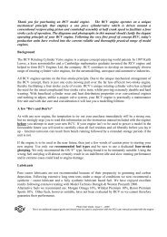
I found the instructions that came with the meter difficult to follow, therefore I put this together hoping it<br />
may help someone else.<br />
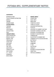
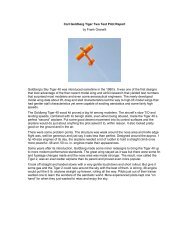
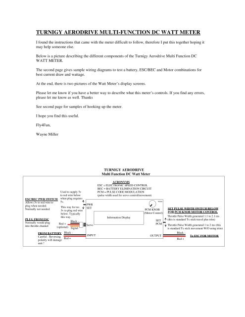
Below is a picture describing the different components of the Turnigy Aerodrive Multi Function <strong>DC</strong><br />
<strong>WATT</strong> <strong>METER</strong>.<br />
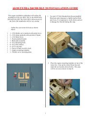
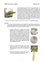
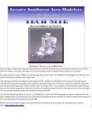
The second page gives sample wiring diagrams to test a battery, ESC/BEC and Motor combinations for<br />
best current draw and wattage.<br />
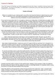
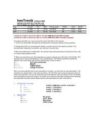
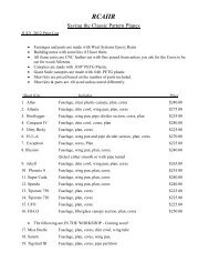
At the end, there is two pictures of the Watt Meter’s display screens.<br />
Please let me know if you have a better way to describe what this meter’s controls. If you find any errors,<br />
please let me know as well. Thanks<br />
See second page for samples of hooking up the meter.<br />
I hope you find this useful.<br />
Fly4Fun,<br />
Wayne Miller<br />
<strong>TURNIGY</strong> <strong>AERODRIVE</strong><br />
Multi Function <strong>DC</strong> Watt Meter<br />
ESC/BEC PWR SWITCH<br />
Allows 5v to red wire to<br />
plug when needed.<br />
Normally not needed.<br />
PLUG FROM ESC<br />
Normally would plug<br />
into throttle channel<br />
FROM BATTERY<br />
Careful - Reversing<br />
polarity will damage<br />
unit !<br />
Used to supply 5v<br />
to red wire below<br />
when plug requires<br />
5v.<br />
This way for no<br />
5v to plug red wire<br />
below. Typically<br />
this way.<br />
Red +<br />
(optional)<br />
Black -<br />
Red +<br />
Black -<br />
Signal<br />
PWR<br />
SET<br />
Servo<br />
INPUT<br />
ACRONYMS<br />
ESC = ELECTRONIC SPEED CONTROL<br />
BEC = BATTERY ELIMINATION CI<strong>RC</strong>UIT<br />
PCM = PULSE CODE MODULATION<br />
(pulse width used for servo control/movement)<br />
Information Display<br />
WRM<br />
PCM KNOB<br />
(Motor Control)<br />
SET<br />
PCM<br />
OUTPUT<br />
SET PULSE WIDTH SWITCH BELOW<br />
FOR PCM KNOB MOTOR CONTROL<br />
Throttle Pulse Width generated 1.1 to 2.1 ms<br />
(this is standard Tx stick travel plus trim)<br />
Throttle Pulse Width generated 1 to 2 ms (this<br />
is standard Tx stick movement W/O using trim)<br />
Black -<br />
Red +<br />
To ESC FOR MOTOR
SAMPLE SETUPS FOR <strong>TURNIGY</strong> <strong>MULTI</strong>_<strong>FUNCTION</strong> <strong>DC</strong> <strong>WATT</strong> <strong>METER</strong><br />
WIRING AND SWITCH SETTING FOR TESTING WHEN RECEIVER's POWER COMES FROM ESC/BEC<br />
PLUG FROM ESC<br />
Normally would plug<br />
into throttle channel<br />
Switch setting when<br />
testing a setup where<br />
ESC/BEC supplies<br />
power to Rx through<br />
plug below. For testing<br />
purposes 5v is turned<br />
off since this unit has<br />
its own internal 5v<br />
and does not need<br />
the ESC/BEC 5v.<br />
PWR<br />
SET<br />
Servo<br />
Signal<br />
Black -<br />
Information Display<br />
PCM KNOB<br />
Motor Control<br />
ESC/BEC<br />
SET<br />
PCM<br />
MOTOR<br />
WRM<br />
Standard Throttle Pulse<br />
Width 1-2 ms<br />
FROM LiPo BATTERY<br />
For Motor and Rx. Careful<br />
reversing polarity will damage<br />
unit !<br />
Black -<br />
Red +<br />
INPUT<br />
OUTPUT<br />
Black -<br />
Red +<br />
WIRING AND SWITCH SETTING FOR MOTOR TESTING - Rx AND MOTOR EACH HAVE THEIR OWN POWER SUPPLIES<br />
REASON RED WIRE IS CUT<br />
When using a separate<br />
battery for Rx, their will<br />
be two Rx power sources.<br />
One from the ESC/BEC<br />
and one from the Rx<br />
battery. To prevent<br />
problems between the<br />
two voltage sources, the<br />
red wire from the ESC/<br />
BEC that plugs into to the<br />
throttle channel is cut.<br />
PLUG FROM ESC<br />
Normally would plug<br />
into throttle channel<br />
Switch Setting when<br />
testing an ESC/BEC<br />
setup where the Rx<br />
in the plane has its<br />
own battery, and<br />
the motor has its own<br />
battery. Red wire to<br />
the ESC will be<br />
cut to eliminate 5v<br />
from ESC/BEC going<br />
to Rx.<br />
Red wire cut<br />
PWR<br />
SET<br />
Servo<br />
Signal<br />
Black -<br />
Information Display<br />
PCM KNOB<br />
Motor Control<br />
ESC/BEC<br />
SET<br />
PCM<br />
MOTOR<br />
WRM<br />
Standard Throttle Pulse<br />
Width 1-2 ms<br />
FROM LiPo BATTERY<br />
For Motor. Careful reversing<br />
polarity will damage<br />
unit !<br />
Black -<br />
Red +<br />
INPUT<br />
OUTPUT<br />
Black -<br />
Red +<br />
FOR TESTING WHEN NO BEC IN ESC. Rx POWERS ESC CONTROL. MOTOR HAS DEDICATED LiPo<br />
Signal<br />
Black -<br />
ESC<br />
MOTOR<br />
WRM<br />
PLUG FROM ESC<br />
Normally would plug<br />
into throttle channel<br />
Switch setting<br />
to supply 5v<br />
to ESC red<br />
wire. In plane Rx<br />
uses power from<br />
Rx to power ESC.<br />
PWR<br />
SET<br />
Servo<br />
Information Display<br />
PCM KNOB<br />
Motor Control<br />
SET<br />
PCM<br />
Standard Throttle Pulse<br />
Width 1-2 ms<br />
FROM LiPo BATTERY<br />
For Motor only. Careful<br />
reversing polarity will<br />
damage unit !<br />
Black -<br />
Red +<br />
INPUT<br />
OUTPUT<br />
Black -<br />
Red +
Pictures of Watt Meter Screen below with alternating screens, the first displays mah on<br />
the screen and the second displays watts on the screen. Also shown is the Hobby King K1<br />
RPM-KV meter attached, both are mounted on a piece of plywood and wired together<br />
since I always use them together.