HIGH SPEED, HIGH ACCURACY COMBINED ... - Davum TMC
HIGH SPEED, HIGH ACCURACY COMBINED ... - Davum TMC
HIGH SPEED, HIGH ACCURACY COMBINED ... - Davum TMC

You also want an ePaper? Increase the reach of your titles
YUMPU automatically turns print PDFs into web optimized ePapers that Google loves.
TECHNICAL BULLETIN TB-7538<br />
<strong>HIGH</strong> <strong>SPEED</strong>, <strong>HIGH</strong> <strong>ACCURACY</strong> <strong>COMBINED</strong><br />
FOOTWEAR / WRIST STRAP TESTER<br />
Installation, Operation and Maintenance<br />
Made in Britain<br />
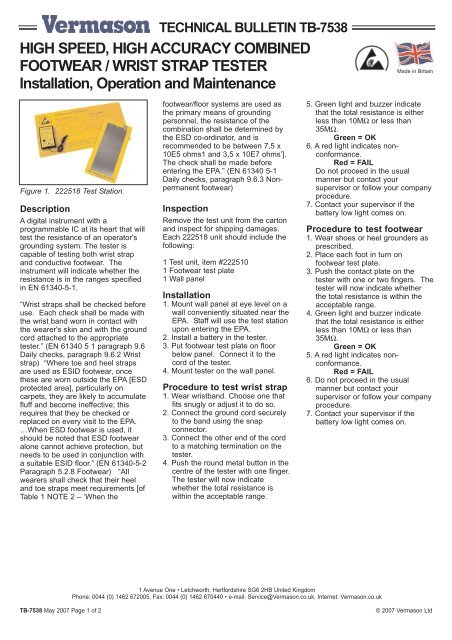
Figure 1. 222518 Test Station.<br />
Description<br />
A digital instrument with a<br />
programmable IC at its heart that will<br />
test the resistance of an operator's<br />
grounding system. The tester is<br />
capable of testing both wrist strap<br />
and conductive footwear. The<br />
instrument will indicate whether the<br />
resistance is in the ranges specified<br />
in EN 61340-5-1.<br />
“Wrist straps shall be checked before<br />
use. Each check shall be made with<br />
the wrist band worn in contact with<br />
the wearer's skin and with the ground<br />
cord attached to the appropriate<br />
tester.” (EN 61340 5 1 paragraph 9.6<br />
Daily checks, paragraph 9.6.2 Wrist<br />
strap) “Where toe and heel straps<br />
are used as ESID footwear, once<br />
these are worn outside the EPA [ESD<br />
protected area], particularly on<br />
carpets, they are likely to accumulate<br />
fluff and become ineffective; this<br />
requires that they be checked or<br />
replaced on every visit to the EPA.<br />
…When ESD footwear is used, it<br />
should be noted that ESD footwear<br />
alone cannot achieve protection, but<br />
needs to be used in conjunction with<br />
a suitable ESID floor.” (EN 61340-5-2<br />
Paragraph 5.2.8 Footwear) “All<br />
wearers shall check that their heel<br />
and toe straps meet requirements [of<br />
Table 1 NOTE 2 – ‘When the<br />
footwear/floor systems are used as<br />
the primary means of grounding<br />
personnel, the resistance of the<br />
combination shall be determined by<br />
the ESD co-ordinator, and is<br />
recommended to be between 7,5 x<br />
10E5 ohms1 and 3,5 x 10E7 ohms’].<br />
The check shall be made before<br />
entering the EPA.” (EN 61340 5-1<br />
Daily checks, paragraph 9.6.3 Nonpermanent<br />
footwear)<br />
Inspection<br />
Remove the test unit from the carton<br />
and inspect for shipping damages.<br />
Each 222518 unit should include the<br />
following:<br />
1 Test unit, item #222510<br />
1 Footwear test plate<br />
1 Wall panel<br />
Installation<br />
1. Mount wall panel at eye level on a<br />
wall conveniently situated near the<br />
EPA. Staff will use the test station<br />
upon entering the EPA.<br />
2. Install a battery in the tester.<br />
3. Put footwear test plate on floor<br />
below panel. Connect it to the<br />
cord of the tester.<br />
4. Mount tester on the wall panel.<br />
Procedure to test wrist strap<br />
1. Wear wristband. Choose one that<br />
fits snugly or adjust it to do so.<br />
2. Connect the ground cord securely<br />
to the band using the snap<br />
connector.<br />
3. Connect the other end of the cord<br />
to a matching termination on the<br />
tester.<br />
4. Push the round metal button in the<br />
centre of the tester with one finger.<br />
The tester will now indicate<br />
whether the total resistance is<br />
within the acceptable range.<br />
5. Green light and buzzer indicate<br />
that the total resistance is either<br />
less than 10MΩ or less than<br />
35MΩ.<br />
Green = OK<br />
6. A red light indicates nonconformance.<br />
Red = FAIL<br />
Do not proceed in the usual<br />
manner but contact your<br />
supervisor or follow your company<br />
procedure.<br />
7. Contact your supervisor if the<br />
battery low light comes on.<br />
Procedure to test footwear<br />
1. Wear shoes or heel grounders as<br />
prescribed.<br />
2. Place each foot in turn on<br />
footwear test plate.<br />
3. Push the contact plate on the<br />
tester with one or two fingers. The<br />
tester will now indicate whether<br />
the total resistance is within the<br />
acceptable range.<br />
4. Green light and buzzer indicate<br />
that the total resistance is either<br />
less than 10MΩ or less than<br />
35MΩ.<br />
Green = OK<br />
5. A red light indicates nonconformance.<br />
Red = FAIL<br />
6. Do not proceed in the usual<br />
manner but contact your<br />
supervisor or follow your company<br />
procedure.<br />
7. Contact your supervisor if the<br />
battery low light comes on.<br />
1 Avenue One • Letchworth, Hertfordshire SG6 2HB United Kingdom<br />
Phone: 0044 (0) 1462 672005, Fax: 0044 (0) 1462 670440 • e-mail: Service@Vermason.co.uk, Internet: Vermason.co.uk<br />
TB-7538 May 2007 Page 1 of 2<br />
© 2007 Vermason Ltd
In case of non-conformance<br />
The instrument measures the<br />
resistance of the external circuit<br />
between the metal contact button and<br />
the cord connectors or the foot test<br />
plates. The wristband and cord, the<br />
plates and the footwear, the<br />
connection to the operator, the<br />
operator's body resistance and the<br />
fingertip button contact are all part of<br />
the circuit. In case of a failure being<br />
indicated, determine whether the<br />
wrist strap or the footwear alone is<br />
failing by ensuring that the other<br />
elements of the circuit are sound.<br />
Note:<br />
If 'battery low' light comes on, insert a<br />
new 9volt alkaline PP3 battery. The<br />
'battery low' threshold is factory set at<br />
6.5 volt.<br />
Calibration<br />
All resistances are in-built using<br />
matched fixed resistors. They are<br />
measured using an ohmmeter, which<br />
is of known accuracy and standards<br />
used are traceable to UKAS. No<br />
variable resistors e.g. potentiometers<br />
are used. The resistances should<br />
nonetheless be re-checked once a<br />
year.<br />
Use a calibration unit such as our<br />
product code 223002.<br />
The potentiometers are accessible<br />
through the two holes on the lefthand<br />
side of the case. The upper<br />
hole allows the upper limit to be<br />
adjusted, the lower hole the lower<br />
limit. Follow the procedure described<br />
on TB-7543. Alternatively, we offer a<br />
calibration service.<br />
Specifications<br />
Resistance Limits<br />
Wrist straps: Low - 0.75MΩ<br />
High - 10 and 35MΩ<br />
Foot wear: Low - 0.1MΩ<br />
High - 10 and 35MΩ<br />
Accuracy ±5%<br />
Weight<br />
Dimensions<br />
0.1kg excluding<br />
battery<br />
145 x 90 x 32mm<br />
Power supply 1 x 9 volt PP3 cell,<br />
preferably alkaline<br />
Battery life typical 3000 tests (3s<br />
per test)<br />
Test voltage<br />
Short circuit<br />
current<br />
maximum 24V<br />
12µA max<br />
Limited Warranty<br />
Vermason expressly warrants that for a period<br />
of one (1) year from the date of purchase,<br />
Vermason High Speed, High Accuracy<br />
Combined Footwear / Wrist Strap Testers will be<br />
free of defects in material (parts) and<br />
workmanship (labour). Within the warranty<br />
period, a unit will be tested, repaired or<br />
replaced at Vermason’s option, free of charge.<br />
Call Customer Service at 0044 (0) 1462<br />
672005 for a Return Material Authorisation<br />
(RMA) and for proper shipping instructions and<br />
address. Any unit under warranty should be<br />
shipped prepaid to the Vermason factory. You<br />
should include a copy of your original packing<br />
slip, invoice, or other proof of purchase date.<br />
Warranty repairs will take approximately two<br />
weeks.<br />
If your unit is out of warranty, Vermason will<br />
quote repair charges necessary to bring your<br />
unit to factory standards. Call Customer<br />
Service at 0044 (0) 1462 672005 for a Return<br />
Material Authorisation (RMA) and proper<br />
shipping instructions and address.<br />
Warranty Exclusions<br />
THE FOREGOING EXPRESS WARRANTY IS<br />
MADE IN LIEU OF ALL OTHER PRODUCT<br />
WARRANTIES, EXPRESSED AND IMPLIED,<br />
INCLUDING MERCHANTABILITY AND<br />
FITNESS FOR A PARTICULAR PURPOSE<br />
WHICH ARE SPECIFICALLY DISCLAIMED.<br />
The express warranty will not apply to defects<br />
or damage due to accidents, neglect, misuse,<br />
alterations, operator error, or failure to properly<br />
maintain, clean or repair products.<br />
Limit of liability<br />
In no event will Vermason or any seller be<br />
responsible or liable for any injury, loss or<br />
damage, direct or consequential, arising out of<br />
the use of or the inability to use the product.<br />
Before using, users shall determine the<br />
suitability of the product for their intended use,<br />
and users assume all risk and liability<br />
whatsoever in connection therewith.<br />
TB-7538 Page 2 of 2<br />
1 Avenue One • Letchworth, Hertfordshire SG6 2HB United Kingdom<br />
Phone: 0044 (0) 1462 672005, Fax: 0044 (0) 1462 670440 • e-mail: Service@Vermason.co.uk, Internet: Vermason.co.uk