SRT-27 Post - Trinity Highway Products, LLC
SRT-27 Post - Trinity Highway Products, LLC
SRT-27 Post - Trinity Highway Products, LLC

You also want an ePaper? Increase the reach of your titles
YUMPU automatically turns print PDFs into web optimized ePapers that Google loves.
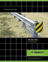
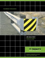
INSTALLATION<br />
The post installation of the <strong>SRT</strong> -<strong>27</strong> AND <strong>SRT</strong> -31 systems should be<br />
per the following <strong>Post</strong> Installation Sections. If there are special field<br />
conditions encountered when installing the <strong>SRT</strong> -<strong>27</strong> and <strong>SRT</strong> -31<br />
systems, contact the state/specifying agency. <strong>Trinity</strong> <strong>Highway</strong> <strong>Products</strong>,<br />
<strong>LLC</strong>. at 1-800-644-7976, is available to assist the state/specifying agency,<br />
if needed.<br />
POST INSTALLATION<br />
Complete the following instructions for the installation of the SYT posts<br />
and the CR posts. When installing posts in rigid pavement, see the <strong>Post</strong><br />
Installed in Rigid Material section, below.<br />
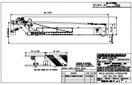
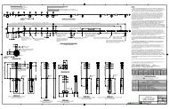
POST LAYOUT<br />
The <strong>SRT</strong> -<strong>27</strong> and <strong>SRT</strong> -31 <strong>Post</strong> System is a 37’6” (11.43m) that utilizes<br />
a straight flare. Complete the following steps to layout the posts. See<br />
Figure 1.<br />
Step<br />
Actions<br />
1 Start at line <strong>Post</strong> 9 of the guardrail run and etc.<br />
2 Extend the guardrail tangent line from <strong>Post</strong> 9 to establish Point<br />
7T. (See Figure 1)<br />
Figure 1<br />
3 Extend the guardrail tangent line from Point 7T to establish Point<br />
1T. See Figure 1.<br />
4 Measure from Point 1T an offset of 4’0” (1.21 m) perpendicular<br />
to the road to establish the back side of the guardrail for Point 1.<br />
5 Measure the offsets of <strong>Post</strong>s 8 and 7.<br />
6 Establish a straight line between Point 1 and Point 7. This line<br />
represents to back side of the guardrail for both of the systems.<br />
7 Between Points 1 and 7 on the back side of the guardrail line,<br />
establish Points 2 thorough 6 at 6’3” (1905 mm) intervals.<br />
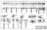
INSTALLING THE SYT POSTS<br />
Complete the following steps to install the SYT posts:<br />
Step<br />
Actions<br />
1. Install the SYT <strong>Post</strong> PN-14578G (<strong>SRT</strong>-<strong>27</strong>) or SYT <strong>Post</strong> PN-<br />
15000G (<strong>SRT</strong> -31) at location 6 through 2, spaced at 6’3”<br />
(1905 mm). Select Option A or Option B for the post installation.<br />
Option<br />
A<br />
Option<br />
B<br />
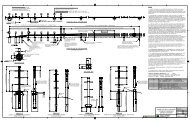
<strong>SRT</strong> LAYOUT<br />
Drive posts into the ground.<br />
1. Drill 12” (300 mm) maximum diameter holes<br />
approximately 44" (1120 mm) deep for the <strong>SRT</strong> -<br />
<strong>27</strong> system or 40” (1020 mm) deep for the <strong>SRT</strong> -<br />
31.<br />
2. Insert the 6' 0" (1830 mm) SYT post into these<br />
holes.<br />
3. Backfill the hole with compactable materials in 6"<br />
(150 mm) lifts and compact with pneumatic<br />
equipment to optimum compaction.<br />
Note: If compactable, the material removed from<br />
the hole may be used for the backfill.<br />
www.highwayguardrail.com 10 Revised: August 24, 2009