Part Two - Geosynthetic Soil Reinforcement - Keystone
Part Two - Geosynthetic Soil Reinforcement - Keystone
Part Two - Geosynthetic Soil Reinforcement - Keystone

Create successful ePaper yourself
Turn your PDF publications into a flip-book with our unique Google optimized e-Paper software.
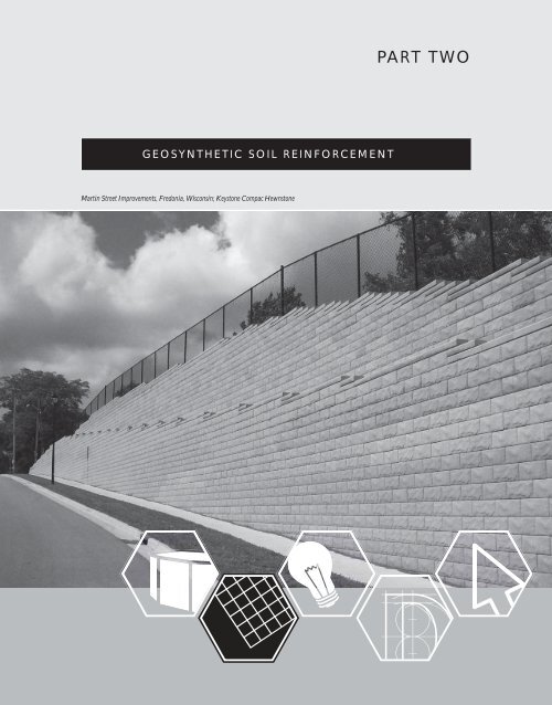
PART TWO<br />
GEOSYNTHETIC SOIL REINFORCEMENT<br />
Martin Street Improvements, Fredonia, Wisconsin; <strong>Keystone</strong> Compac Hewnstone
DESIGN MANUAL<br />
& KEYWALL OPERATING GUIDE<br />
GEOSYNTHETIC SOIL REINFORCEMENT<br />
<strong>Keystone</strong> retaining walls may perform as gravity retaining walls for heights up to 6 ft (1.8m) for Standard units<br />
and 3.3ft (1m) for Compac units, depending on geometry, soil type, and specific loading. When a wall exceeds<br />
safe gravity heights, soil reinforcement is required to provide stability against overturning and sliding. The<br />
majority of <strong>Keystone</strong> retaining walls are constructed using geosynthetic reinforcement, which is the focus of this<br />
manual and the KeyWall program. Design for inextensible steel reinforcement is discussed in the <strong>Keystone</strong> KeySystem<br />
design manual and HITEC Evaluation, August 2000.<br />
<strong>Soil</strong>-reinforced walls typically consist of geosynthetic materials, primarily geogrids, which are connected to the<br />
<strong>Keystone</strong> units and placed in horizontal layers in the compacted backfill. A limit equilibrium design procedure is used<br />
to determine the number, strength, length, and distribution of geosynthetic reinforcement layers required to form a<br />
stable soil-reinforced mass.<br />
<strong>Geosynthetic</strong> material design parameters in the limit equilibrium analysis are:<br />
• Long-Term Design Strength (LTDS) and allowable strength, T al<br />
• <strong>Geosynthetic</strong>-<strong>Keystone</strong> unit connection strength, T cl , T sc<br />
• <strong>Geosynthetic</strong>-soil pullout interaction coefficient, C i<br />
• <strong>Geosynthetic</strong>-soil direct shear coefficient, C ds<br />
Terminology used to define geosynthetic soil reinforcement tensile strength varies somewhat between authors,<br />
specifiers, and suppliers. The terminology used within this section is consistent with that of NCMA and AASHTO/<br />
FHWA, unless otherwise noted.<br />
Wall construction with Geogrid <strong>Reinforcement</strong>.<br />
2.1
PART TWO<br />
<strong>Geosynthetic</strong> <strong>Soil</strong> <strong>Reinforcement</strong><br />
DESIGN STRENGTH<br />
The practice for determining the allowable tensile strength of geosynthetic reinforcement, (Tal), is based<br />
upon the U.S. Federal Highway Administration guidelines. This method establishes the Long Term<br />
Design Strength (LTDS), be based on sustained load testing, extrapolated to a design life for the structure.<br />
The Long-Term Design Strength (LTDS), for geogrid reinforcement utilized in the <strong>Keystone</strong> Retaining<br />
Wall design is:<br />
Equation (2a) LTDS =<br />
T ult<br />
RF cr x RF id x RF d<br />
There are two design philosophies currently employed in retaining wall design and analysis. Allowable Stress<br />
Design (ASD) is the conventional working stress and factor of safety method of analysis that has been used<br />
for years. Limit State Design (LSD) or Load and Resistance Factor Design (LRFD) is the newer method that<br />
compares factored loads to factored resistances.<br />
Allowable Stress Design<br />
The long-term design strength (LTDS), is reduced by an overall safety factor (FS), in Allowable Stress<br />
design to account for all factors on loads, uncertainties, etc.<br />
Equation (2b) T al =<br />
LTDS<br />
FS<br />
Limit State Design (LRFD)<br />
The Long Term Design Strength (LTDS) is reduced by a resistance factor (φ) in Limit State Design/<br />
(LRFD) to account for material uncertainty.<br />
Equation (2c) T al = φ GEO LTDS<br />
The NCMA, Rankine, AASHTO 96, and AASHTO Simplified design methods in KeyWall employ<br />
Allowable Stress design procedures. The AASHTO LRFD, Canadian LRFD and Australian design methods<br />
in KeyWall employ Limit State design procedures.<br />
Tensile Strength (T ult )<br />
T ult is the ultimate strength of geosynthetic reinforcing when tested in a wide width test per ASTM D4595<br />
(geotextile) or D6637 (geogrid). This value is reported as the Mean Average Roll Value (MARV),<br />
as determined by the manufacturer’s quality control process and accounting for statistical variation.<br />
2.2
DESIGN MANUAL<br />
& KEYWALL OPERATING GUIDE<br />
REDUCTION FACTORS<br />
RF cr<br />
RFcr is the reduction factor to account for the long-term creep characteristic of polymetric materials. The<br />
long-term tension-strain-time behavior of polymeric reinforcement is determined from results of controlled<br />
laboratory creep tests conducted on finished-product specimens for periods up to 10,000 hours per ASTM<br />
D5262 and D6992. The data is then extrapolated to the project design life of the structure, 75 years or 100<br />
years. Creep rupture testing is similar to the procedure described above, however, the load at which rupture<br />
may occur at the end of the design life is predicted. A combination of 10,000 hour testing and creep rupture<br />
testing appears to be the current standard for evaluating geosynthetic material creep. Typical range of RF cr<br />
is 1.4 to 5.0.<br />
RF id<br />
RFid is the reduction factor for installation damage (i.e., cuts, nicks, tears, etc.) created by fill placement and<br />
construction equipment operations with various backfill material that can potentially reduce reinforcing<br />
strength and performance. The recommended reduction factor for reinforcement installation damage is<br />
based on results of full-scale construction damage tests. Site specific values may be determined by<br />
performing construction damage tests for the selected geosynthetic material with project specific<br />
backfill and equipment. Typical range of RFid is 1.05 to 2.00.<br />
Note:<br />
KeyWall permits the<br />
choice of three different<br />
backfill materials<br />
(fine-grained soils,<br />
3⁄4- inch (20 mm) minus,<br />
and 2 inch (50 mm)<br />
minus), which establish<br />
a default value for the<br />
installation damage<br />
factors used in the<br />
LTDS determination,<br />
based on the<br />
manufacturer’s<br />
recommendations<br />
and testing.<br />
RF d<br />
RFd is the reduction factor to account for the effects of chemical and biological exposure to the<br />
reinforcement that are dependent on material composition, including resin type, resin grade, additives,<br />
manufacturing process, and final product physical structure. For most soils used with the <strong>Keystone</strong> System,<br />
the manufacturers have included recommended factors to account for possible chemical and biological<br />
degradation. In soils where high alkalinity or other aggressive factors (ph < 3 or > 9) may be present, the<br />
manufacturer should be contacted for specific recommendations. Typical range of RFd is 1.0 to 2.0.<br />
For further information on the chemical and biological durability of a reinforcement, a review of durability<br />
is presented in FHWA-NHI-09-087 “Corrosion/Degradation of <strong>Soil</strong> Reiforcement for MSE Walls and<br />
Reinforced <strong>Soil</strong> Slopes.”<br />
FS<br />
FS is the overall tension safety factor for material, geometric, and loading uncertainties that cannot be<br />
specifically accounted for. FS is similar to other overall safety factors in Allowable Stress design. A<br />
minimum factor of safety of 1.5 is required for most permanent applications. For unusual loading<br />
conditions, variable or poorly defined soil conditions, this factor may be increased at the discretion of<br />
the designer.<br />
φ GEO<br />
φ GEO is the geosynthetic resistance factor for material uncertainty used in Limit State Design. The US<br />
AASHTO LRFD Code uses 0.90 for the tensile resistance factor. Resistance factors will vary in Limit<br />
State Design based on the load/resistance factor system adopted by specific design codes.<br />
2.3
PART TWO<br />
<strong>Geosynthetic</strong> <strong>Soil</strong> <strong>Reinforcement</strong><br />
CONNECTION STRENGTH<br />
Note:<br />
Reinforced soil wall<br />
designs are unique to<br />
the specific <strong>Keystone</strong><br />
units and geosynthetic<br />
reinforcement used.<br />
Connection data is<br />
specific to each<br />
combination and<br />
reinforcement level.<br />
Substitution of any<br />
materials invalidates a<br />
given wall design.<br />
The connection strength is the strength state reinforcement-facing connection strength. The capacity is<br />
dependent upon the vertical depth to the reinforcement, wall geometry, type of <strong>Keystone</strong> unit utilized, and<br />
the specific geosynthetic utilized.<br />
Laboratory testing is required to define the connection strength for specific units and geosynthetic materials<br />
at varying normal pressures. Typical graphs for an individual stress-strain test and complete series plot is<br />
shown in Figure 2:1 and Figure 2:2 per NCMA Test Method SRWU-1/ASTM D6638.<br />
Connection Load<br />
Load at 3/4"<br />
3/4" Deformation<br />
Peak Load<br />
Failure<br />
Stress/strain plot<br />
Displacement<br />
Figure 2:1 Load Test at one Normal Force<br />
Connection Load<br />
y<br />
θ<br />
θ<br />
Peak Load Plot<br />
Max<br />
3/4" Load Plot<br />
Max<br />
Tconn = y + N tan θ Max<br />
Normal Force<br />
Figure 2:2 Connection Load Plots at Different Normal Forces<br />
2.4
DESIGN MANUAL<br />
& KEYWALL OPERATING GUIDE<br />
CONNECTION STRENGTH<br />
In Allowable Stress design, the calculated tensile load at each reinforcement level in the geosynthetic must<br />
be less than 1) the allowable geosynthetic design strength, T al , and 2) an ultimate connection strength limit,<br />
T cl , divided by a safety factor (T cl / FS). The recommended minimum factor of safety on the ultimate<br />
connection strength is 1.5.<br />
In Limit State/LRFD design, the factored tensile load at each reinforcement level in the geosynthetic must<br />
be less than 1) the allowable geosynthetic design stsrength, T al , and 2) the ultimate connection strength limit,<br />
T cl , times the appropriate resistance factor (φ).<br />
Serviceability strength, T sc , is defined as the connection strength at a maximum 0.75-inch (20mm)<br />
movement, as determined with the NCMA Test Method SRWU-1/ASTM D6638. Serviceability criteria is<br />
only considered when a service state analysis is being performed. This is rarely considered in current MSE<br />
wall design as service state deformation is not well undersood. NCMA and AASHTO design codes<br />
generally ignore the service state condition and require a strength analysis only.<br />
GEOSYNTHETIC-SOIL INTERACTION COEFFICIENT<br />
<strong>Two</strong> types of soil-reinforcement interaction coefficients or interface shear strength parameters are used for<br />
design of soil reinforced structures: pullout interaction coefficient, C i , and direct shear coefficient, C ds .<br />
The pullout interaction coefficient is used in stability analysis to compute the frictional resistance along<br />
the reinforcement/soil interface in the zone beyond a defined plane of failure. The calculation yields the<br />
capacity to resist pullout of the reinforcement from the soil.<br />
The direct shear coefficient is used to determine the factor of safety against outward sliding of the wall mass<br />
along the layers of reinforcement. The coefficients are determined in the laboratory and are a function of<br />
soil and geosynthetic material types.<br />
Design pullout resistance of the geosynthetic reinforcement is defined as the ultimate tensile load<br />
required to generate movement of the reinforcement through the soil mass measured at a maximum ¾<br />
inch (19 mm) displacement. The recommended minimum factor of safety against geosynthetic pullout is<br />
1.5. Equivalent resistance factors are used in limit state design. ASTM D6706 may be used to determine<br />
pullout coefficients for geogrids.<br />
Note: AASHTO requires that 1000 hour sustained load testing be performed on all geosynthetic connection<br />
schemes for MSE walls per FHWA guidelines. This testing can result in an additional reduction factor that<br />
reduces connection capacity over the life of the structure. There is no evidence that connection creep is a long term<br />
performance consideration based on the thousands of walls constructed since the 1980’s. NCMA does not recognize<br />
the concept in their “Design Manual for Segmental Retaining Walls” and <strong>Keystone</strong> has not observed this in<br />
practice. The most probable explanation is that the “Design” loads never materialize at the connection as extensible<br />
reinforcement can “yield” to release any stress build up while the surrounding soil and reinforcement picks up the<br />
load (ie, arching). Current US practice is to analyze the connection at 100% of the theoretical design load in the<br />
reinforcement which overstates the load and probably explains the lack of creep related connection isuses.<br />
2.5
PART TWO<br />
<strong>Geosynthetic</strong> <strong>Soil</strong> <strong>Reinforcement</strong><br />
GEOSYNTHETIC-SOIL INTERACTION COEFFICIENT<br />
Note:<br />
These coefficients do not<br />
apply to Geotextiles or<br />
“fat” soils.<br />
KeyWall 2010 uses the following default values for C i and C ds based upon the phi angle inputted for the<br />
reinforced fill material.<br />
<strong>Soil</strong> Type (USC*) φ ANGLE C i C d<br />
Crushed Stone, Gravel (GW, GM) φ > 32° 0.9 0.9<br />
Sand, Gravel, Silty Sands (SW, SM, SP) φ > 28° 0.8 0.8<br />
Sandy Silt, Lean Clay (SC, ML, CL) φ > 25° 0.7 0.7<br />
Other clay (CL/CH) φ < 25° 0.6** 0.6**<br />
* (USC is the Unified <strong>Soil</strong> Classification System per ASTM D-2487)<br />
** (Consult geogrid manufacturer)<br />
Note:<br />
As new materials are<br />
developed or new data is<br />
provided, KeyWall’s data<br />
files will be updated.<br />
<strong>Keystone</strong> provides the<br />
data as a service to its<br />
customers and to ensure<br />
data uniformity for<br />
<strong>Keystone</strong> design. This<br />
information is provided<br />
with no written or<br />
implied warranty as to<br />
the accuracy of the data<br />
supplied. Data values<br />
should be verified with<br />
the manufacturers.<br />
GEOGRID MANUFACTURERS’ DATA<br />
Geogrid manufacturers were contacted during the development of this <strong>Keystone</strong> Design Manual and asked<br />
to provide the required information to evaluate their design parameters. The material provided and testing<br />
performed by <strong>Keystone</strong> is the basis for the values programmed into KeyWall. Information provided to<br />
<strong>Keystone</strong> by the geogrid manufacturers/suppliers is available directly from the geogrid manufacturers.<br />
2.6