E N D U R A N C E - Yuasa Batteries, UPS Batteries, Industrial ...
E N D U R A N C E - Yuasa Batteries, UPS Batteries, Industrial ...
E N D U R A N C E - Yuasa Batteries, UPS Batteries, Industrial ...

Create successful ePaper yourself
Turn your PDF publications into a flip-book with our unique Google optimized e-Paper software.
ENDURANCE<br />
B A T T E R I E S<br />
VALVE REGULATED<br />
R E C H A R G E A B L E<br />
B A T T E R I E S<br />
M A N U A L
ontents...<br />
C O N T E N T S<br />
Introduction 4<br />
Typical Applications 4<br />
Construction 4<br />
Features 5<br />
Sizing Combinations 6<br />
Gas Recombination Mechanism 7<br />
General Specifications 10<br />
Performance Data ‘Amps’ 11<br />
Performance Data ‘Watts’ 12<br />
Discharge 13<br />
Charging 14<br />
Test 19<br />
Design Life 19<br />
Inspection and Handling 21<br />
Cautions 22<br />
Installation Services 23<br />
Battery Racks 24<br />
Glossary 25<br />
t h r e e<br />
Y U A S A B A T T E R I E S
INTRODUCTION<br />
The YUASA ‘Endurance’ range of sealed lead acid batteries has been designed<br />
to meet the expanding requirements of supplying power for communications,<br />
emergency power supplies and many other applications.<br />
YUASA Endurance range fully compliant with IEC 896-2.<br />
YUASA Endurance <strong>Batteries</strong> have been designed and tested to ensure full compliance<br />
with BS 6290 Part 4 (1997) and require virtually no maintenance<br />
throughout the designed service life of 10 years plus.<br />
TYPICAL APPLICATIONS<br />
.<br />
❖<br />
❖<br />
❖<br />
❖<br />
❖<br />
❖<br />
❖<br />
Telephone Exchanges<br />
Telecommunications<br />
Uninterruptible Power Supplies (<strong>UPS</strong>)<br />
Emergency Lighting<br />
Alarm Systems<br />
Security Systems<br />
Computers<br />
CONSTRUCTION<br />
YUASA Endurance <strong>Batteries</strong> are designed so that the necessary quantity of<br />
electrolyte is absorbed within the plates and separators making it possible through<br />
gas recombination technology to provide a valve regulated lead acid battery,<br />
commonly referred to as sealed or maintenance free.<br />
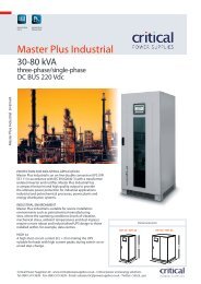
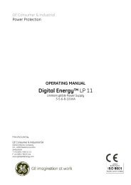
The construction and features of YUASA Endurance <strong>Batteries</strong> are shown in<br />
Fig. 1 and Table 1 respectively.<br />
fig. 1...<br />
TERMINAL POST<br />
SEALING COMPOUND<br />
O'RING<br />
STRAP COVER<br />
VENT VALVE<br />
COVER<br />
LID<br />
INTER-CELL<br />
CONNECTOR<br />
NEGATIVE PLATE<br />
ELEMENT PROTECTOR<br />
SEPERATOR<br />
POSITIVE PLATE<br />
CONTAINER<br />
YUASA<br />
ENDURANCE<br />
6V,100Ah EN100-6<br />
valve regulated<br />
sealed lead-acid type<br />
rechargeable battery<br />
YUASA BATTERY (UK) LTD.<br />
f o u r<br />
Y U A S A B A T T E R I E S
PARTS<br />
Postitive and<br />
negative plates<br />
Separator<br />
Electrolyte<br />
Case components:<br />
container, lid,<br />
vent cover and<br />
battery cover<br />
Intercell connectors<br />
Safety vent valve<br />
Strap cover<br />
Terminal<br />
MATERIAL<br />
Heavy duty anti-corrosive lead<br />
calcium alloy grids pasted with<br />
active material<br />
Microfine fibre mat with<br />
excellent heat oxidation<br />
properties<br />
Dilute sulphuric acid fully<br />
absorbed by plates and<br />
separators<br />
Injection moulded flame retardant<br />
ABS polymer<br />
Heavy duty anti-corrosive lead<br />
alloy, squeeze welded together<br />
through the container wall<br />
Synthetic rubber moulded cap<br />
Moulded polypropylene<br />
THREADED<br />
BRASS INSERT<br />
LEAD ALLOY POST<br />
SEALING COMPOUND<br />
'O' RING COMPRESSOR<br />
'O' RING<br />
table 1...<br />
FUNCTION<br />
❖ Retain sufficient capacity<br />
❖ Maintain capacity performance throughout design life<br />
❖ Minimize self-discharge<br />
❖ Prevents short circuit between (+) & (-) plates<br />
❖ Retains electrolyte<br />
❖ Prevents active material shedding<br />
❖ Causes electro chemical reaction in (+) and (-) plates<br />
❖ Provides heat sealed compartment for 2V cell groups<br />
❖ Withstands thermal and mechanical shock<br />
❖ Integral lifting handle incorporated into lid design for ease<br />
of handling<br />
❖ Interconnect positive plates of 1 cell with negative plates of<br />
adjoining cell<br />
❖ Transmits battery power from plates to battery terminals<br />
❖ Capable of carrying ultra high current even total short<br />
circuit load<br />
❖ Releases gas if internal pressure rises abnormally high<br />
❖ Normalises internal pressure<br />
❖ Prevents air ingress<br />
❖ Prevents short circuit due to positive plate growth<br />
❖ Provides maximum conductivity enhancing high rate<br />
discharge characteristics<br />
❖ Provides dual-seal construction of ‘O’-ring and sealing<br />
compound to ensure a perfect seal<br />
❖ 8 mm thread insert allows easy installation<br />
FEATURES<br />
FLAME RETARDANT<br />
WELDED LID/CONTAINER<br />
SEALED CONSTRUCTION<br />
LOW MAINTENANCE<br />
The container, lid, valve cover and final battery cover are moulded in high<br />
flame retardant ABS.<br />
The lid and container are joined together by means of a heat seal producing a<br />
high integrity weld between container and lid.<br />
No electrolyte leakage will occur from battery terminals or case, ensuring safe<br />
and efficient operation.<br />
Endurance <strong>Batteries</strong> utilise the gas recombination system which transforms the<br />
generated gas into water, thus no topping up is required throughout the life of<br />
the battery.<br />
f i v e<br />
Y U A S A B A T T E R I E S
FEATURES (Cont.)<br />
ELECTROLYTE SUSPENSION<br />
VENTING SYSTEM<br />
LONG LIFE<br />
NO EQUALISING CHARGE<br />
Endurance batteries can be mounted in any orientation since all electrolyte is retained<br />
within the battery plates and separators. (Excluding continuous use inverted.)<br />
In the event of overcharge the Endurance batteries are fitted with a safe low pressure<br />
venting system which automatically reseals after releasing any excess pressure.<br />
Heavy duty lead calcium alloy grids and intercell connectors with anticorrosive<br />
construction enable the Endurance <strong>Batteries</strong> to remain in service for a<br />
design life of 10 years.<br />
No equalising charge is required during normal float charge operation.<br />
SIZING COMBINATIONS<br />
PARALLEL CONNECTION<br />
Endurance batteries have been specifically designed so as to allow parallel<br />
networks of different capacity to be used within a common system. This greatly<br />
extends the selection of capacities that can be achieved.<br />
Each Endurance battery has been designed using a common plate size with a<br />
nominal capacity of 20Ah per plate. For example, the EN100 (100Ah) is<br />
constructed using five of the 20Ah plates per cell, whereas the EN480 (480Ah)<br />
utilises twenty-four 20Ah plates per cell. This simplistic design strategy, therefore,<br />
allows any multiple parallel combination of the basic model range.<br />
The following list, details some of the possible capacity variations that can be<br />
achieved utilising the base Endurance models:<br />
chart 1...<br />
AH CAPACITY<br />
REQUIRED<br />
ENDURANCE PARALLEL<br />
STRING COMBINATIONS<br />
80 EN80<br />
100 EN100<br />
160 EN160<br />
180 EN80 + EN100<br />
200 EN100 x 2<br />
240 EN80 x 3<br />
260 EN100 + EN160<br />
300 EN100 x 3<br />
320 EN320<br />
400 EN100 x 4<br />
420 EN100 + EN320<br />
480 EN480<br />
500 EN100 x 5<br />
580 EN100 + EN480<br />
640 EN320 x 2<br />
ETC/ETC<br />
2020 EN480 x 4 + EN100<br />
2080 EN480 x 4 + EN160<br />
2240 EN480 x 4 + EN320<br />
2400 EN480 x 5<br />
Notes<br />
1. This design feature is only particular to the Endurance range.<br />
2. Endurance batteries should not be connected in parallel to any other makes or<br />
ranges of batteries.<br />
3. Only parallel mixing is allowed, no battery types including the Endurance<br />
range should be mixed in SERIES strings.<br />
s i x<br />
Y U A S A B A T T E R I E S
GAS RECOMBINATION MECHANISM<br />
The chemical reaction taking place in a lead-acid storage battery is as shown in<br />
the formula:<br />
PbO 2 + 2H 2 SO 4 + Pb<br />
Discharge<br />
PbSO 4<br />
+<br />
2H 2 O + PbSO 4<br />
Charge<br />
(Lead dioxide) (Sulphuric acid) (Spongy lead) (Lead sulphate) (Water) (Lead sulphate)<br />
Positive Electrolyte Negative Positive Electrolyte Negative<br />
Active Active Active Active<br />
Material Material Material Material<br />
➞➞<br />
At discharge lead dioxide in positive plates and spongy lead in negative plates<br />
react with sulphuric acid in the electrolyte and gradually transform into lead<br />
sulphate, during which the sulphuric acid concentration decreases.<br />
Conversely, when the battery is charged, the positive and negative active materials<br />
which had been turned into lead sulphate gradually revert to lead dioxide and<br />
spongy lead respectively, releasing the sulphuric acid absorbed in the active materials,<br />
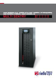
during which the sulphuric acid concentration increases, as shown in Fig. 2.<br />
When battery charging approaches its final stage, the charging current is<br />
consumed solely for electrolytic decomposition of water in the electrolyte, resulting<br />
in generation of oxygen gas from positive plates and hydrogen gas from negative<br />
plates. The generated gas will escape from the battery causing a decrease of<br />
the electrolyte, thereby requiring occasional water replenishment.<br />
However, YUASA Endurance <strong>Batteries</strong> utilise the characteristics of spongy lead,<br />
or negative active material, which is very active in moist conditions and reacts<br />
very quickly with oxygen, thereby suppressing the decrease of water eliminating<br />
the need of water replenishment.<br />
fig. 2...<br />
REACTION FROM BEGINNING OF CHARGE TO BEFORE THE FINAL STAGE<br />
i<br />
-<br />
Charger<br />
e<br />
+<br />
-<br />
+<br />
Negative<br />
Positive<br />
Pb+SO 4<br />
- 4H + +SO 4<br />
- +PbO 2 +2e -<br />
⎧<br />
⎨⎩<br />
2H 2 SO 4<br />
Pb+SO 4<br />
- +2e - 2H 2<br />
O+PbSO 4<br />
-<br />
The process of charging from its beginning to the final stage is identical with that<br />
of conventional batteries as shown in Fig. 2.<br />
s e v e n<br />
Y U A S A B A T T E R I E S
On the one hand, after the final stage of charging or under overcharge condition,<br />
the charging energy is consumed for electrolytic decomposition of water, and the<br />
positive plates generate oxygen gas which reacts with the spongy lead in negative<br />
plates and the sulphuric acid in electrolyte, turning a part of negative plates into a<br />
discharged condition, thus suppressing the hydrogen gas generation from negative<br />
plates.<br />
The part of negative plates which had turned to discharged condition through<br />
reaction with oxygen gas is then reverted to original spongy lead by subsequent<br />
charge. Thus, a negative plate keeps equilibrium between the amount which turns<br />
into spongy lead by charging and the amount of spongy lead which turns into lead<br />
sulphate through absorbing the gas generated from positive plate, which makes it<br />
possible for the battery to be of a sealed type.<br />
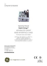
The chemical reaction which takes place after the final stage of charging or under<br />
overcharge condition is as shown in Fig. 3 and the reaction formula is described<br />
below<br />
1<br />
Reaction at positive plate (oxygen generation)<br />
1<br />
2H 2 O ➛ O 2 + 4H + + 4emigrates<br />
to negative plate ➛<br />
surface<br />
2<br />
Reaction at negative plate<br />
2<br />
(chemical reaction of spongy lead with oxygen)<br />
2Pb + O 2<br />
➛ 2PbO<br />
3<br />
(chemical reaction of PbO with electrolyte)<br />
2PbO + 2H 2 SO 4<br />
➛<br />
2PbSO 4 + 2H 2 O<br />
➛ (To reaction 1 )<br />
4<br />
(Reduction of PbSO 4 )<br />
2PbSO 4 + 4H + + 4e- ➛ 2Pb + 2H 2 SO 4<br />
➛ (To reaction 3 )<br />
➛ (To reaction 2 )<br />
Total reaction at negative plate<br />
O 2 + 4H + 4e-<br />
➛<br />
2H 2 O<br />
e i g h t<br />
Y U A S A B A T T E R I E S
REACTION AFTER FINAL STAGE OF CHARGE<br />
fig. 3...<br />
i<br />
-<br />
Charger<br />
+<br />
Negative<br />
e<br />
Positive<br />
2<br />
1<br />
2H 2 O<br />
2Pb+ O 2<br />
2PbO<br />
O 2<br />
4H + +<br />
4e<br />
4<br />
2Pb- 2H 2 SO 4<br />
4e-<br />
2P 2 SO 4<br />
- 4H - PbO 2<br />
3<br />
2PbO +<br />
2H 2 SO 4<br />
2Pb 2<br />
SO 4<br />
2H 2 O<br />
As described above, the oxygen gas generated from the positive plates reacts<br />
quickly with the active material in charged condition in the negative plates<br />
and returns to water causing very little loss thereof, thus making it possible<br />
to build the battery in a sealed construction.<br />
n i n e<br />
Y U A S A B A T T E R I E S
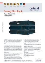
GENERAL SPECIFICATIONS<br />
chart 2...<br />
BATTERY<br />
MODEL<br />
NOMINAL<br />
VOLTAGE<br />
(V)<br />
NOMINAL CAPACITY<br />
TO 1.80V/CELL<br />
(AH/10HR)<br />
TO 1.70V/CELL<br />
(AH/3HR)<br />
LENGTH<br />
DIMENSIONS (mm) ± 2mm<br />
WIDTH<br />
HEIGHT<br />
OVERALL<br />
HEIGHT<br />
(Inc. Cover)<br />
BATTERY<br />
WEIGHTS<br />
(Kg)<br />
TERMINAL<br />
EN80-4 4 80 68.7 200 208 234 238 17 8mm<br />
STUD<br />
EN80-6 6 80 68.7 200 208 234 238 22 8mm<br />
STUD<br />
EN100-4 4 100 85.8 200 208 234 238 17.5 8mm<br />
STUD<br />
EN100-6 6 100 85.8 200 208 234 238 23 8mm<br />
STUD<br />
EN160-4 4 160 139 206 210 236 240 24 8mm<br />
STUD<br />
EN160-6 6 160 139 305 210 236 240 35 8mm<br />
STUD<br />
EN320-2 2 320 278 206 210 236 240 24 8mm<br />
STUD<br />
EN480-2 2 480 417 305 210 236 240 35 8mm<br />
STUD<br />
200 ± 2mm<br />
EN80/<br />
EN100<br />
305 ± 2mm<br />
EN160-6<br />
SHOWING 2 x ICB168<br />
M8<br />
ICB 168<br />
ICB 168<br />
208 ± 2mm<br />
210 ± 2mm<br />
234 ± 2mm<br />
236 ± 2mm<br />
206 ± 2mm<br />
EN160-4/<br />
EN320-2<br />
305 ± 2mm<br />
EN480-2<br />
210 ± 2mm<br />
210 ± 2mm<br />
236 ± 2mm<br />
236 ± 2mm<br />
t e n<br />
Y U A S A B A T T E R I E S
PERFORMANCE DATA<br />
table 2...<br />
END<br />
VOLTS<br />
per cell<br />
MINUTES<br />
AMPS / AH 20°C<br />
AUTONOMY<br />
HOURS<br />
5 10 15 20 25 30 45 1 1.5 2 3 4 5 6 7 8 9 10 24<br />
1.60 3.4 2.4 1.9 1.5 1.3 1.2 .89 .72 .52 .41 .29 .23 .19 .16 .14 .13 .11 .1 .04<br />
1.63 3.3 2.4 1.8 1.5 1.3 1.1 .88 .72 .52 .41 .29 .23 .19 .16 .14 .13 .11 .1 .04<br />
1.65 3.2 2.3 1.8 1.5 1.3 1.1 .88 .71 .51 .41 .29 .23 .19 .16 .14 .13 .11 .1 .04<br />
1.67 3.1 2.3 1.8 1.5 1.3 1.1 .87 .71 .51 .41 .29 .23 .19 .16 .14 .13 .11 .1 .04<br />
1.70 3.1 2.2 1.8 1.5 1.3 1.1 .87 .70 .51 .41 .29 .22 .18 .16 .14 .13 .11 .1 .04<br />
1.75 2.7 2.1 1.7 1.4 1.2 1.1 .85 .68 .5 .39 .28 .22 .18 .16 .14 .12 .11 .1 .04<br />
1.80 2.4 1.9 1.5 1.3 1.1 1 .81 .66 .48 .38 .27 .21 .18 .15 .13 .12 .11 .1 .04<br />
1.85 2 1.6 1.3 1.2 1 .97 .76 .62 .46 .37 .27 .21 .17 .15 .13 .12 .11 .1 .04<br />
Constant current discharge performance data.<br />
Table 2 titled ‘AMPS/AH 20°C’ will allow battery selection to be made for<br />
Constant Current load conditions, the table is generic to Endurance batteries and<br />
should be used by mapping the requiried load time to the allowed end of<br />
discharge voltage ‘End Volts’. The figure obtained is the Constant Current<br />
available for each 1Ah Endurance battery unit, divide this number into the<br />
required load and the answer is the battery capacity required to supply the<br />
required load.<br />
Example:<br />
Load condition 22A constant current.<br />
Load time 4 hrs.<br />
Load voltage, nominal 48V to end voltage 40.8V.<br />
1. As lead acid batteries have a nominal single cell voltage of 2V each, divide<br />
nominal load voltage by 2 to determine the number of cells required. 48V/2V<br />
= 24.<br />
2. Divide End voltage by the answer to 1 above, to determine End Volts per<br />
cell. 40.8V/24 = 1.7.<br />
3. Map End Volts per cell ‘1.7’ against Load time ‘4 hrs’ answer 0.22.<br />
4. Divide answer 0.22 into Load 22A equals battery capacity required 100(Ah).<br />
5. From Chart 2 select battery model and quantity EN100-6 times 8pcs.<br />
e l e v e n<br />
Y U A S A B A T T E R I E S
ENDURANCE<br />
table<br />
3...<br />
END<br />
VOLTS<br />
per cell<br />
WATTS / CELL / AH 20°C<br />
AUTONOMY<br />
MINUTES<br />
HOURS<br />
5 10 15 20 25 30 35 40 45 50 55 1 1.5 2 2.5 3<br />
1.60 6.5 4.8 3.8 3.1 2.6 2.3 2 1.8 1.7 1.6 1.5 1.3 0.99 0.79 0.66 0.56<br />
1.63 6.5 4.8 3.8 3.1 2.6 2.3 2 1.8 1.7 1.6 1.5 1.3 0.99 0.78 0.66 0.56<br />
1.65 6.3 4.7 3.8 3.1 2.6 2.3 2 1.8 1.7 1.6 1.4 1.3 0.99 0.78 0.66 0.56<br />
1.67 6.1 4.6 3.7 3 2.6 2.3 2 1.8 1.6 1.6 1.4 1.3 0.98 0.77 0.64 0.55<br />
1.70 5.8 4.4 3.5 3 2.6 2.3 2 1.8 1.6 1.5 1.4 1.3 0.98 0.77 0.64 0.55<br />
1.75 5.4 4.2 3.4 2.9 2.5 2.2 1.9 1.7 1.6 1.5 1.4 1.3 0.96 0.75 0.64 0.54<br />
1.80 4.7 3.7 3.1 2.6 2.3 2 1.9 1.7 1.6 1.5 1.4 1.2 0.93 0.74 0.62 0.53<br />
1.85 4 3.4 2.9 2.5 2.2 1.9 1.8 1.6 1.5 1.4 1.3 1.2 0.89 0.72 0.6 0.52<br />
Constant power discharge performance data.<br />
Table 3 titled ‘Watts/Cell/AH 20°C’ will allow battery selection to be made for<br />
Constant Power load conditions, the table is generic to Endurance batteries and<br />
should be used by mapping the requiried load time to the allowed end of<br />
discharge voltage ‘End Volts’. The figure obtained is the Constant Power<br />
available for each 1Ah Endurance Cell, divide this number into the required load<br />
per cell and the answer is the battery capacity required to supply the required<br />
load.<br />
Example:<br />
Load condition 24Kw dc constant power, 20°C.<br />
Load time 30min.<br />
Load voltage, maximum 272V to end voltage 204V.<br />
1. The recommended float voltage for Endurance battery cells (20°C) is 2.26V<br />
each, therefore divide maximum load voltage by 2.26 to determine the<br />
number of cells required. 272V/2.26V = 120 cells.<br />
2. Divide End voltage by the answer to 1 above, to determine End Volts per<br />
cell. 204/120 = 1.7<br />
3. Map End Volts per cell ‘1.7’ against Load time ‘30min’ answer 2.1 watts per<br />
1Ah cell.<br />
4. Divide Load condition by cells required to give ‘Required Watts per cell’.<br />
24,000/120 = 202.26.<br />
5. Divide answer 2.1 into Required Watts per cell to find minimum battery<br />
capacity required in AmpereHours. 202.26/2.1 = 96.3(Ah).<br />
6. From Charts 1 and 2 select battery model/model combination equal or<br />
greater than 96.3Ah. Note. As many batteries are supplied in monoblock<br />
design, the cell count may need to be divided by the number of cells per<br />
monoblock to determine the required quantity of monoblocks.<br />
7. Solution EN100-6 times 40pcs in series.<br />
t w e l v e<br />
Y U A S A B A T T E R I E S
DISCHARGE<br />
DISCHARGE<br />
CHARACTERISTICS<br />
Discharge capacity varies depending on the discharge current (hour rate).<br />
The smaller the discharge current, the more the capacity increases, and the larger<br />
the discharge current, the less the capacity.<br />
Discharge capacity also varies according to battery temperature.<br />
The lower the temperature, the less the capacity.<br />
Fig. 4 shows the constant current discharge characteristics of batteries when they<br />
are discharged to the final discharge voltage at various discharge currents at 20°C.<br />
fig. 4...<br />
DISCHARGE CHARACTERISTIC CURVE AT 20°C<br />
V<br />
V<br />
TERMINAL VOLTAGE (Volt)<br />
6.5<br />
6.0<br />
5.5<br />
5.0<br />
4.5<br />
4CA<br />
3CA<br />
2CA<br />
1CA<br />
0.65CA<br />
0.27CA<br />
0.1CA<br />
2.16<br />
2<br />
1.83<br />
1.66<br />
1.5<br />
1 2 4 6 8 10 20 40 60 80 100 200 400 600<br />
DENOTES FINAL VOLTAGE<br />
DISCHARGE TIME (Min.)<br />
Fig. 5 shows the relationship of temperature with capacity.<br />
For example at 0.1C discharge: a battery capable of discharging for 10 hours at<br />
20°C will decrease the discharge duration to about 8 hours (84%) at -5°C.<br />
t h i r t e e n<br />
Y U A S A B A T T E R I E S
TEMPERATURE AND DISCHARGE CAPACITY<br />
fig. 5...<br />
PERCENTAGE OF CAPACITY AVAILABLE (%)<br />
120<br />
100<br />
80<br />
60<br />
40<br />
20<br />
0<br />
-20<br />
-10 0 10 20 30 40<br />
TEMPERATURE (o C)<br />
0.1CA<br />
0.65CA<br />
1.0CA<br />
3.0CA<br />
CHARGING<br />
CHARGING<br />
CHARACTERISTICS<br />
Float charge voltage must be kept at a value high enough to compensate for the<br />
battery’s self-discharge to keep the battery in a fully charged condition at all times<br />
but low enough to minimise life deterioration due to possible overcharge.<br />
The optimum charge voltage for YUASA Endurance Battery is 2.26V per cell*<br />
under normal temperature condition (20°C (68°F)).<br />
The YUASA Endurance Battery requires no equalizing charge.<br />
This is because of its low self-discharge rate resulting in a minimal variation<br />
among the cells in the battery bank and float charge at sufficient voltage to maintain<br />
it in a fully charged condition.<br />
Recovery charge after the battery has been discharged can be carried out at the<br />
float charge voltage of 2.26V/cell.*<br />
Fig. 6 shows the charge characteristics at a constant current (0.1C(A)) and constant<br />
voltage (2.26V) 10HR rated capacity.<br />
The time required to complete the charging varies by the amount of the previous<br />
discharge, initial charge current and temperature.<br />
As shown in Fig. 6 charging a fully discharged battery by constant current and<br />
constant voltage of 0.1C(A) and 2.26V* respectively at 20°C will put back more<br />
than 100% of the previous discharge in 24 hours.<br />
Since the battery does not restrict the size of initial charge current, making it<br />
larger will shorten the time for a charge of more than 100%.<br />
Fig. 7 shows the relationship of charge voltage and current at float charge with gas<br />
recombination efficiency.<br />
If the battery is charged at a voltage of 2.26V per cell,* a trickle current just<br />
necessary to maintain the battery in fully charged condition will flow at the final<br />
stage of charging, and the gas recombination efficiency is maintained at nearly<br />
100%. The final stage current will increase when the temperature is high, and<br />
decrease when low.<br />
* Tolerance Range: 2.26V ± 0.005V.<br />
f o u r t e e n<br />
Y U A S A B A T T E R I E S
CHARGING CHARACTERISTICS<br />
fig. 6...<br />
CHARGE<br />
VOLUME<br />
%<br />
CHARGING<br />
CURRENT<br />
(A)<br />
CHARGED<br />
VOLTAGE<br />
(V)<br />
0.1C Amp (max.) 2.26V/Cell Constant Voltage at 20oC<br />
100<br />
0.1C<br />
2.4<br />
CHARGED VOLUME<br />
80<br />
0.08C<br />
2.3<br />
CHARGE VOLTAGE<br />
60<br />
0.06C<br />
2.2<br />
40<br />
0.04C<br />
2.1<br />
AFTER 50% DISCHARGE<br />
AFTER 100% DISCHARGE<br />
20<br />
0.02C<br />
2.0<br />
CHARGING CURRENT<br />
0 4 8 12 16 20 24 28<br />
CHARGING TIME (HOURS)<br />
GAS RECOMBINATION EFFICIENCY<br />
fig. 7...<br />
GAS RECOMBINATION EFFICIENCY (%)<br />
100<br />
80<br />
60<br />
40<br />
20<br />
0<br />
0.0005 0.001 0.005 0.05 0.1 0.5<br />
CHARGING CURRENT (CA)<br />
3.0<br />
2.8<br />
2.6<br />
2.4<br />
2.2<br />
2.0<br />
CELL VOLTAGE (V/Cell)<br />
f i f t e e n<br />
Y U A S A B A T T E R I E S
TEMPERATURE COMPENSATION<br />
As temperature rises, electrochemical activity in a battery increases and conversely<br />
decreases as temperature falls. Therefore, as the temperature rises, the charging voltage<br />
should be reduced to prevent overcharge and increased, as the temperature falls,<br />
to avoid undercharge. In general, in order to attain optimum service life, the use of<br />
a temperature compensated charger is recomended. The recommended compensation<br />
factor for EN batteries is -3mV/°C/Cell (for float/standby). The standard<br />
centre point for temperature compensation is 20°C. Fig. 8 shows the relationship<br />
between temperatures and charging voltages.<br />
In practice where there are short term temperature fluctuations between 5°C and<br />
40°C, temperature compensation is not absolutely essential. However, it is desirable<br />
to set the voltage at a value shown in Fig. 8 which, as closely as possible, corresponds<br />
to the average ambient temperature of the battery during its service life.<br />
When designing a charger equipped with temperature compensation, the<br />
temperature sensor should sense only the temperature of the battery. Therefore,<br />
consideration should be given to thermally isolating the battery and temperature<br />
sensor from other heat generating components in the system.<br />
fig. 8...<br />
RELATIONSHIP BETWEEN TEMPERATURE AND CHARGING VOLTAGE<br />
CHARGING VOLTAGE (V/CELL)<br />
2.5<br />
2.4<br />
2.3<br />
2.2<br />
2.1<br />
2.0<br />
-10 0 10 20 30 40 50<br />
TEMPERATURE (° C)<br />
s i x t e e n<br />
Y U A S A B A T T E R I E S
fig. 9...<br />
CHARGING CHARACTERISTICS OF ENDURANCE BATTERIES<br />
DEPTH OF<br />
DISCHARGE (%C10)<br />
0<br />
CHARGED<br />
VOLUME (%C10)<br />
110<br />
100<br />
Charging at 2.26vpc/0.1C-Amps<br />
current limit/Ambient temp. 20˚C<br />
10<br />
90<br />
20<br />
80<br />
30<br />
40<br />
70<br />
60<br />
50<br />
50<br />
60<br />
70<br />
80<br />
40<br />
30<br />
20<br />
90<br />
10<br />
100<br />
0<br />
0 2 4 6 8 10 12 14 16 18 20 22 24<br />
DURATION (HOURS)<br />
RECHARGE<br />
CHARACTERISTICS<br />
When a battery has been subjected to a discharge (i.e. required to support a load),<br />
it may be useful to know how long it will take to reach a specified state of charge.<br />
This will depend on the following factors: Battery Capacity; Depth of Discharge;<br />
Charger voltage and current limits.<br />
An example is given below using figure 9. Charger limits given as 2.26Vpc and<br />
0.1C Amps.<br />
Method<br />
(1) Calculate Discharged Capacity (C)<br />
(a) Constant Current Load<br />
Discharged Capacity (Ah) = Current (A) x Time (hrs)<br />
(b) Constant Power Load<br />
Discharged Capacity (Ah) = Power (Watts/cell) x Time (hrs)<br />
End Voltage (Vpc)<br />
Example<br />
C = 60A x 1hr<br />
= 60Ah<br />
C = 160Wpc x 1hr<br />
1.65Vpc<br />
= 97Ah<br />
(2) Calculate Depth of Discharge (DoD) For EN160Ah<br />
DoD = Discharge Capacity x 100% DoD = 97Ah x 100%<br />
Nominal Capacity<br />
160Ah<br />
= 60%<br />
s e v e n t e e n<br />
Y U A S A B A T T E R I E S
From figure 9 read down the left hand axis ‘Depth of Discharge’ to the calculated<br />
value (e.g. 60% DoD in examples (a) and (b) above). Reading across onto the<br />
‘Charged Volume Axis’ note that when the battery is 60% DoD it is still 40%<br />
charged. Trace along the ‘Charged Volume’ curve until the required state of<br />
charge (Charged Volume), is reached.<br />
e.g. Battery will be 80% charged after approx. 4 hours.<br />
Battery will be 95% charged after approx. 7 hours.<br />
This calculation is an approximation only. To be safe it is advisable to add 10% to<br />
the calculated time. Therefore in the examples shown the recharge times will be<br />
4 hours 30mins to 80% charged and 7 hours 45mins to 95% charged.<br />
SELF-DISCHARGE CHARACTERISTICS OF ENDURANCE BATTERIES<br />
STORAGE<br />
CHARACTERISTICS<br />
The rate of self-discharge is less than 0.08% per day when the battery is left standing<br />
at 20°C. As shown in Fig. 10 in storage for one year at 20°C, the capacity<br />
decrease is about 29%.<br />
This low rate of self-discharge is because of the use of lead-calcium alloy which is<br />
one-fourth to one-fifth that of a battery using lead-antimony alloy.<br />
The higher the temperature, the more the self-discharge, and therefore storage for a<br />
long period at elevated temperature should always be avoided.<br />
fig. 10...<br />
REMAINING CAPACITY (%)<br />
100<br />
80<br />
10°C<br />
20°C<br />
60<br />
30°C<br />
40<br />
40°C<br />
20<br />
0<br />
0 2 4 6 8 10 12<br />
STORAGE PERIOD (MONTH)<br />
e i g h t e e n<br />
Y U A S A B A T T E R I E S
INTERNAL RESISTANCE<br />
The internal resistance (Impedance) of a battery is the lowest when the battery is<br />
in a fully charged state. Fig. 11 shows the change in internal resistance of<br />
Endurance <strong>Batteries</strong> during<br />
fig.<br />
discharge.<br />
11...<br />
INTERNAL RESISTANCE OF ENDURANCE BATTERIES<br />
IR(mΩ )<br />
25.0<br />
20.0<br />
15.0<br />
10.0<br />
5.0<br />
0<br />
TERMINAL VOL.<br />
6.0<br />
5.5<br />
5.0<br />
1 2 3 4 5 6 7 8 9 10<br />
DISCHARGE TIME (HOUR)<br />
EN 100-6 (AT 20°C)<br />
Fig. 11 shows the internal resistance of a battery measured through a 1000Hz AC<br />
bridge.<br />
TEST<br />
Impedance testing can be performed using the <strong>Yuasa</strong> YPI-2 Impedance/comparator<br />
test meter, this form of testing is non-intrusive and can be performed online<br />
with the battery still connected within its system. (Note: The YPI-2 meter cannot<br />
be used where a high AC ripple content exists.) By using this test method deterioration<br />
can be detected without removing the battery from its standby mode.<br />
Dedicated literature is available on request.<br />
DESIGN LIFE<br />
LIFE CHARACTERISTICS<br />
Within the recommended operating temperature of 15°C-25°C and under<br />
optimum float conditions, the service life is expected to exceed 10 years.<br />
The length of float charge life is influenced by discharge frequency, discharge<br />
depth, float charge voltage and service environment.<br />
At normal float charge voltage (2.26V per cell), the gas absorption mechanism<br />
described previously will have the negative plates absorb the gas generated in the<br />
battery returning it into water and, therefore, capacity decrease due to electrolyte<br />
depletion will not occur.<br />
Corrosion speed will be accelerated as the temperature rises, making the life shortened.<br />
Also the higher the charge current, the faster the corrosion, therefore it is<br />
necessary to float-charge the battery at the proper voltage.<br />
The float charge voltage should always be set at 2.26V ± 0.005V.<br />
n i n e t e e n<br />
Y U A S A B A T T E R I E S
fig. 12...<br />
ACCELERATED LIFE CHARACTERISTICS OF ENDURANCE BATTERIES<br />
As the result of an accelerated life test by overcharge (at 20°C) in which an overcharge<br />
amount corresponding to over 10 year floating charge was given, the<br />
capacity decrease was found by about 10%.<br />
Although the battery life in actual service will vary depending on temperatures<br />
and other operating conditions, the designed Life of a YUASA Endurance Battery<br />
under normal operating conditions (e.g. total discharge amount per month is less<br />
than the rated capacity and used under temperatures of 20-30°C) can be estimated<br />
as shown in Fig. 12 when the above test data and the life characteristics of conventional<br />
stationary lead-acid batteries are taken into account.<br />
t w e n t y<br />
Y U A S A B A T T E R I E S
INSPECTION AND HANDLING<br />
RECEIVING<br />
The battery is delivered in a charged condition. Please note the following points<br />
before installation.<br />
Ignitable gases may be generated from the storage battery. Provide sufficient<br />
ventilation and keep the battery away from sparks and naked flame.<br />
Upon arrival, inspect for any damage to the packages, and then unpack them<br />
carefully being careful not to damage the battery.<br />
Perform the unpacking at a place adjacent to the battery installation location.<br />
Take out the battery by supporting it at the bottom, not by lifting the terminals.<br />
Be careful that the seal may be disrupted if the battery is moved with force<br />
imposed on the terminals.<br />
After unpacking, check the quantity of accessories and the appearance.<br />
INSTALLATION<br />
(1) After verifying no abnormalities in the battery, install it on the prescribed<br />
location (e.g. cubicle or battery stand).<br />
(2) If the battery is to be accommodated in a cubicle, place it at the lowest part<br />
of the cubicle whenever it is practicable.<br />
(3) When connecting the batteries, free air space must be provided between<br />
each battery. The recommended minimum space between batteries is 0.02 inches<br />
(5 mm) to 0.04 inches (10 mm).<br />
(4) Always avoid installing the battery close to a heat source (such as a transformer).<br />
(5) Since a storage battery may generate ignitable gases, avoid installing close to<br />
any item that produces sparks (such as switch fuses).<br />
(6) Before making connections, polish the joint surfaces of the battery terminals<br />
to bright metal by a wire brush.<br />
(7) Apply lightly a rust preventive agent for lead acid storage batteries on connections<br />
of the storage battery.<br />
(8) When a multiple number of batteries are used, first make the inter-battery<br />
connections in a correct manner, and then connect the battery to the charger or<br />
the load.<br />
In these cases, the positive (+) pole of the storage battery should be securely connected<br />
to the positive (+) terminal of the charger or the load, and negative (-) to<br />
negative (-).<br />
If the storage battery and the charger are connected erroneously, the charger will<br />
be damaged. Be sure not to make an erroneous connection.<br />
The tightening torque for each connecting bolt and nut shall be<br />
6.1 Nm (54 lbf. in).<br />
t w e n t y - o n e<br />
Y U A S A B A T T E R I E S
STORAGE<br />
(1) When you wish to store the battery, disconnect it from the charger and<br />
load, and store it. If possible, at a dry location with low temperature.<br />
(2) If batteries are stored for a long period, give a supplementary charge<br />
before service.<br />
SUPPLEMENTARY CHARGE<br />
(1) Part of the battery capacity will have been lost due to self-discharge during<br />
transportation or storage. Give supplementary charge before putting into service.<br />
(2) The supplementary charge should be given by the following conditions<br />
before putting into service.<br />
STORAGE CHARGE VOLTAGE CHARGE TIME<br />
PERIOD PER CELL MIN MAX<br />
Not more than<br />
1 Year<br />
1~2 Years<br />
2.26V/cell<br />
2.31V/cell<br />
2.31V/cell<br />
More than 3 days<br />
2~6 days<br />
3~6 days<br />
MAINTENANCE<br />
A dedicated maintenance guide is available on request.<br />
The guide includes a ‘sample’ site log sheet for record purposes.<br />
CAUTIONS<br />
(1) Only clean batteries using a damp cloth. Never allow the battery to be<br />
splashed or deposited with oils or organic solvents such as gasoline and paint<br />
thinner, nor have it cleaned with cloths impregnated with these materials.<br />
Avoid dusting by ‘cloth duster’ or cleaning by dry cloth (particularly chemical<br />
textile) as they will generate static electricity which is dangerous.<br />
(2) A storage battery may generate ignitable gases. Never place near a naked<br />
flame or short circuit the battery.<br />
(3) If sulphuric acid is deposited due to mechanical damage on to skin or<br />
clothes, wash immediately with water.<br />
If splashed into the eyes, wash with a large amount of fresh water and get<br />
immediate medical attention.<br />
(4) DO NOT INCINERATE batteries as they are likely to rupture. <strong>Batteries</strong><br />
that have reached the end of their service life can be returned to us for safe<br />
disposal.<br />
(5) To obtain optimum service life, the ripple current at R.M.S. should be<br />
regulated below 0.1C(A).<br />
(6) When the storage battery is to be mounted in a container, a ventilation<br />
opening should be provided.<br />
Any cubicle or storage room containing batteries should be provided with<br />
sufficient ventilation.<br />
t w e n t y - t w o<br />
Y U A S A B A T T E R I E S
(7) Touching electrically conductive parts may result in a electric shock. Be sure<br />
to wear rubber gloves before inspection or maintenance work.<br />
(8) Heat kills batteries. Avoid placing batteries in close proximity to heat sources<br />
of any kind. The longest service life will be attained when the battery is operated<br />
around an ambient temperature of 20°C (77°F).<br />
(9) If 4 or more battery groups are to be used in parallel connection, consult with<br />
us prior to use.<br />
(10) Mixed use of batteries with different histories and of different manufacturer<br />
is liable to cause damage to the battery or to the associated equipment. Consult<br />
with us if such necessity is present.<br />
(11) The battery is manufactured from high impact ABS plastic resin, placing it<br />
in an atmosphere of, or in contact with organic solvents or adhesive materials<br />
should be avoided.<br />
(12) Do not lift or carry a battery by its terminals.<br />
(13) Ripple current (the AC component on the DC charge current). Ideally this<br />
should be zero, as it will reduce the service life of a cell/battery, the larger the<br />
component the greater the reduction it will cause. For example 0.1C Amps<br />
R.M.S. will reduce the optimum service life by a minimum 3%.<br />
Note<br />
I) Ripple current can be source or load generated.<br />
II) Ripple current can vary with load change and is often its greatest at part load.<br />
INSTALLATION SERVICES<br />
A full range of associated site services is available to support <strong>Yuasa</strong> customers<br />
throughout the UK, these services include:<br />
❖<br />
❖<br />
❖<br />
❖<br />
❖<br />
❖<br />
Site surveys.<br />
CAD Designed layouts.<br />
Installation.<br />
Commissioning.<br />
Maintenance testing.<br />
Battery recovery and safe disposal.<br />
For further details, please contact the <strong>Yuasa</strong> Technical Services department.<br />
t w e n t y - t h r e e<br />
Y U A S A B A T T E R I E S
BATTERY RACKS<br />
A wide variety of easy to assemble, sturdy steel battery racks are available to suit<br />
your installation requirements, should you require any information about these,<br />
or require further assistance regarding battery selection or installation, please contact<br />
your nearest YUASA Sales Company.<br />
t w e n t y - f o u r<br />
Y U A S A B A T T E R I E S
GLOSSARY<br />
1. Ampere (A)............. The unit for measuring the flow of electric current.<br />
2. Ampere hour (Ah)... The current in (A amperes) multiplied by time in (h hours). Used to<br />
indicate the capacity of a battery.<br />
3. Capacity (C)............ Ampere hours that can be discharged from a battery. This unit is relative<br />
to time.<br />
4. Cell......................... The minimum unit of which a battery is composed, consisting of positive<br />
and negative plates, separators, electrolyte, etc. In valve regulated lead acid<br />
batteries, the nominal voltage is 2 volts per cell.<br />
5. Charging................. The process of storing electrical energy in a battery in a chemical form.<br />
6. Cyclic Service.......... The use of a battery with alternate repetition of charging and discharging.<br />
7. Cycle Service Life.... The total number of cycles expected at a given depth of discharge.<br />
8. Deep Discharge....... (a) Discharge of a battery until 100% of the capacity is exhausted.<br />
(b) Discharge of a battery until the voltage under load drops below the<br />
specified final discharge voltage (Over discharge).<br />
9. Depth of Discharge<br />
(DoD).....................<br />
The ratio of discharge capacity vs. the rated capacity of a battery.<br />
10. Discharge................. The process of drawing stored energy out of a battery in the form of<br />
electrical power.<br />
11. End Voltage......... This is the lowest voltage (measured at the leading battery terminals) that<br />
the battery can discharge down to while still supporting the Load.<br />
12. Energy Density......... The ratio of energy that can be discharged from a battery to the volume of<br />
that battery measured in Watt Hours (WH) per cubic inch or litre.<br />
13. Float Service............ Method of use in which the battery and the load are connected in parallel<br />
to a float charger (or rectifier) so the constant voltage is applied to the<br />
battery continuously, maintaining the battery in a fully charged state and to<br />
supply power to the load from the battery without interruption or load<br />
variation.<br />
14. Gas Recombination.. The process by which oxygen gas generated from the positive plates<br />
during the final stage of charging is absorbed into the negative plates,<br />
reducing the potential at the negative plates, so suppressing the generation<br />
of hydrogen.<br />
15. Impedance............... The ratio of voltage variation vs. current variation in alternating (a.c.) supply.<br />
16. Internal Resistance... The term given to the resistance inside a battery, consisting of the sum of<br />
resistance of the electrolyte, the positive and negative plates and separators,<br />
etc.<br />
17. Life Expectancy........ Expected service life of a battery expressed in total cycles or time in float.<br />
t w e n t y - f i v e<br />
Y U A S A B A T T E R I E S
GLOSSARY Cont.<br />
18. Load........................ The amount of dc electrical power to be supported by the battery, may be<br />
expressed as constant current ‘Amps’ or constant power ‘Watts’.<br />
19. Nominal Capacity...... The nominal value of rated capacity. In ‘Endurance’ range value regulated<br />
lead acid batteries nominal capacity is usually measured at the 10 hour rate.<br />
20. Nominal Voltage...... The nominal value of rated voltage. In lead acid batteries, nominal voltage<br />
is 2 volts per cell.<br />
21. Open Circuit Volts... The voltage of a battery which is isolated electrically from any external<br />
circuit, i.e. the voltage is measured in a no load condition.<br />
22. Parallel Connection... Connection of a group of batteries by interconnecting all terminals of the<br />
same polarity, thereby increasing the capacity of the battery group but not<br />
increasing voltage.<br />
23. Recovery Charge..... The process of charging a discharged battery to restore its capacity in<br />
preparation for subsequent discharge.<br />
24. Sealed...................... The word ‘Sealed’ is used as a relative term when referring to cells in<br />
EN batteries compared with open vented free eletrolyte types.<br />
25. Self Discharge.......... Loss of capacity without external current drain.<br />
26. Series Connection.... Connection of a group of batteries by sequentially interconnecting the<br />
terminals of opposite polarity thereby increasing the voltage of the battery<br />
group but not increasing capacity.<br />
27. Shallow Discharge.... Discharge of a battery in which discharge is less than 50% depth of<br />
discharge (DoD).<br />
28. Shelf Life................. The maximum period of time a battery can be stored, under specified<br />
conditions, without needing supplementary charging.<br />
29. Standby Service........ General term for an application in which the battery is maintained in a<br />
fully charged condition by trickle or float charging. Synonymous with<br />
Float Service.<br />
30. Trickle Charge......... Continuous charging by means of a small current designed to compensate<br />
for self discharge in a battery which is isolated from any load. For valve<br />
regulated lead acid batteries, constant voltage charging is common.<br />
31. Charged Volume..... The power returned to the battery by charging as a percentage of the<br />
power taken out during discharge.<br />
32. VCP (vcp)..... Term for volts per cell.<br />
33. Watt..... The SI unit for power, equivalent to 1 joule per second.<br />
E. & O. E.<br />
t w e n t y - s i x<br />
Y U A S A B A T T E R I E S
UNIT 22 RASSAU INDUSTRIAL ESTATE<br />
EBBW VALE, GWENT, NP23 5SD<br />
TEL: 08708 500312 FAX: 08708 500317<br />
WEBSITE: WWW.YUASA-BATTERY.CO.UK<br />
YUASA BATTERY (EUROPE) GMBH,<br />
TIEFENBROICHER WEG 28, 4000 DÜSSELDORF 30,<br />
TELEFON: (0211) 41790-0, FAX: (0211) 41790-11<br />
Issue date July 98