Operation Manual - Critical Power Supplies
Operation Manual - Critical Power Supplies
Operation Manual - Critical Power Supplies

You also want an ePaper? Increase the reach of your titles
YUMPU automatically turns print PDFs into web optimized ePapers that Google loves.
INTRODUCTIONThank you for choosing our product.Our company is specialised in designing, developing and manufacturing uninterruptible power supplies (UPS).The UPS described in this manual is a high quality product which has been carefully designed and built in order to guaranteethe highest levels of performance.This manual contains detailed instructions for using and installing the product.For information about using and getting the most out of your appliance, this manual must be stored with care in thevicinity of the UPS and CONSULTED BEFORE OPERATING ON IT.NOTE: Some images contained within this document are for indication purposes only and therefore may not identically matchthe products in use.ENVIRONMENTAL PROTECTIONDuring the development of its products, the company uses extensive resources with regards to all environmental aspects.All our products pursue the objective defined in the environmental management system developed by the company incompliance with standards in force.No hazardous materials such as CFC, HCFC or asbestos are used in this product.When evaluating packaging, the choice of material has been made favouring recyclable materials.For correct disposal, please separate and identify the type of material of which the packaging is made in the table below.Dispose of all material in compliance with standards in force in the country in which the product is used.DESCRIPTIONPalletPackaging cornerBoxAdhesive padProtective bagMATERIALHeat-treated pineStratocell/cardboardCardboardStratocellHD PolyethyleneDISPOSING OF THE PRODUCTThe UPS contains internal material that (in case of dismiss / disposal) are considered TOXIC and HAZARDOUS WASTE, suchas electronic circuit boards and batteries. Treat these materials according to the laws applicable referring to qualified servicepersonnel. Their proper disposal contributes to respect the environment and human health.© The reproduction of any part of this manual, in whole or in part, is forbidden without the prior consent of the manufacturer.In order to make improvements, the manufacturer reserves the right to modify the product described at any moment and without notice.
CONTENTSOVERVIEW 5MULTI SENTRY 5MCT VIEWS 6MST VIEWS 7VIEW OF THE UPS CONNECTIONS 8VIEW OF THE CONTROL PANEL 9BATTERY BOX (OPTIONAL) 10SEPARATE BYPASS INPUT (OPTIONAL) 11INTERNAL TRANSFORMER 11ADDITIONAL INTERNAL BATTERY CHARGERS 11INSTALLATION 12STORING THE UPS AND THE BATTERY BOX 12PREPARING FOR INSTALLATION 12PRELIMINARY INFORMATION 12ELECTROMAGNETIC COMPATIBILITY 13INSTALLATION ENVIRONMENT 13REMOVING THE UPS AND THE BATTERY BOX FROM THE PALLET 14PRELIMINARY CHECK OF CONTENTS 16INSTALLING THE UPS AND THE BATTERY BOX 16STEPS TO BE TAKEN TO GAIN ACCESS TO THE TERMINALS OF THE UPS / BATTERY BOX 16ELECTRICAL CONNECTIONS 17WIRING DIAGRAMS FOR CONNECTING TO THE ELECTRICAL SYSTEM 17INTERNAL PROTECTIVE DEVICES OF THE UPS 20EXTERNAL PROTECTIVE DEVICES 21CROSS SECTION OF THE CABLES 22CONNECTIONS 22CONNECTIONS OF THE MODEL WITH SEPARATE BYPASS 23R.E.P.O. 23EXTERNAL SYNC 23CONNECTING THE REMOTE MAINTENANCE BYPASS 24CONNECTING THE BATTERY BOX TO THE UPS 26MULTIPLE EXPANSIONS 27SETTING THE RATED BATTERY CAPACITY – SOFTWARE CONFIGURATION 27
EXTERNAL TEMPERATURE PROBE 28REMOTE PANEL (OPTIONAL) 28USE 29DESCRIPTION 29PRELIMINARY OPERATIONS 30POWERING ON FOR THE FIRST TIME 31POWERING ON FROM THE MAINS 32POWERING ON FROM THE BATTERY 32POWERING OFF THE UPS 32GRAPHIC DISPLAY 33DISPLAY MENUS 34OPERATING MODES 35MAINTENANCE BYPASS (SWMB) 35REDUNDANT AUXILIARY POWER SUPPLY FOR AUTOMATIC BYPASS 36PROGRAMMABLE AUXILIARY SOCKET (POWER SHARE) 36POWER WALK-IN 36REDUCING THE LOAD (TO 200V AND 208V) 36CONFIGURING THE UPS 37COMMUNICATION PORTS 39RS232 AND USB CONNECTORS 39COMMUNICATION SLOTS 39AS400 PORT 40BUZZER 41SOFTWARE 42MONITORING AND CONTROL SOFTWARE 42CONFIGURATION SOFTWARE 42TROUBLESHOOTING GUIDE 43STATUS / ALARM CODES 47TECHNICAL DATA 51
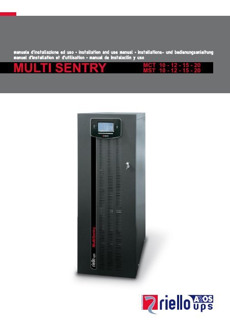
OVERVIEWMULTI SENTRYThe UPS units of the Multi Sentry 10 – 12 – 15 – 20 kVA range (VFI-SS-111 type) have been designed using the latesttechnology available today so as to guarantee users maximum performance. The use of the new control PCBs based onmultiprocessor architecture (DSP + µP inside) together with high frequency IGBT technology offers excellent performance bothin the input stage (absorbed current harmonic distortion ≤ 3%) and in output (output voltage distortion ≤ 1%).Thanks to these and many other features plus the easy-to-use design, the Multi Sentry represents a new reference standard inthe three-phase UPS sector.Depending on user requirements, there are two different versions available:MCTThe Multi Sentry MCT version stands out by itscompact size and new, modern design. Thesefeatures make it suitable for any environment.MSTThe Multi Sentry MST version, offers longerautonomy than the MCT version, thanks to thepossibility to double the number of batteries inside thecabinet.Nominal power10 kVA 12 kVA 15 kVA 20 kVA10000 VA9000 W12000 VA10800 W15000 VA13500 W20000 VA18000 WOutput power factor 0.9 0.9 0.9 0.9Weight (withbatteries)MCT 180 Kg 182 Kg 190 Kg 195 KgMST 305 Kg 310 Kg 315 Kg 320 KgW x D x HMCTMST320 x 840 x 930 mm440 x 850 x 1320 mmAccessoriesBattery cabinets – Communication boards – Remote mimic panel
MCT VIEWSBattery start button (COLD START)<strong>Manual</strong> bypass switchBattery fuse holder isolatorOutput switchSeparate bypass switch (optional)Input switchTerminal cover panelBrake rodSlots for accessory communication cardsCommunication ports (AS400, USB, RS232)<strong>Power</strong>share sockets (10A max. total on the twosockets) and relative protectionVentilation fansParallel PCB (optional)1/0 main power switch
MST VIEWSBattery start button (COLD START)<strong>Manual</strong> bypass switchBattery fuse holder isolatorOutput switchSeparate bypass switch (optional)Input switchTerminal cover panelBrake rodSlots for accessory communication cardsCommunication ports (AS400, USB, RS232)<strong>Power</strong>share sockets (10A max. total on the twosockets) and relative protectionVentilation fansParallel PCB (optional)Remote Emergency <strong>Power</strong> Off (R.E.P.O.)
VIEW OF THE UPS CONNECTIONSConnection for the R.E.P.O command (Remote Emergency <strong>Power</strong> Off)(see previous page for the MST version)<strong>Power</strong> connections: BATTERY, INPUT, SEPARATE BYPASS (optional), OUTPUTConnection for remote maintenance bypass commandConnection for external Battery Box temperature probeConnection for external synchronization signalSlot for power relay board
VIEW OF THE CONTROL PANELGraphic display Function keys *Left-hand LEDs area:Mains power LEDBattery power LEDLoad on bypass LEDRight-hand LEDs area:Stand-by / alarm LEDBattery low LEDECO mode LED* The function of each key is indicated at the bottom of the display and varies according to the menu used.
BATTERY BOX (OPTIONAL)THE BATTERY BOX IS AN OPTIONAL ACCESSORY.The Battery Box contains batteries that increase the operating time of the UPS during prolonged black-outs. The number ofbatteries contained in it will vary according to the type of UPS to which the Battery Box is to be installed. The utmost attentionmust be paid to ensure that the battery voltage of the Battery Box corresponds to that supported by the UPS.Additional Battery Boxes may be connected in a chain to obtain the desired autonomy time during a power failure.This series of Battery Box contains two separate strings of batteries, one with a positive voltage and the other with a negativevoltage with respect to the neutral terminal (N).The basic diagram for the Battery Box is shown here below.BBX 1320 480VBB NP T4 3FBBX 1320 480VBB NP T2 3FBBX 1320 480VBB NP T8 3FBBX 1320 480VBB NP T5 3FRated voltage 240 + 240 Vdc 240 + 240 Vdc 240 + 240 Vdc 240 + 240 VdcWeight 300 Kg 390 Kg 395 Kg 400 KgW x D x H400 x 815 x 1320 mm
SEPARATE BYPASS INPUT (OPTIONAL)THE DI (OPTIONAL) VERSION OF THE UPS SERIES HAS SEPARATE BYPASS AND INPUT LINES.The UPS series with separate Bypass ensures a separate connection between the input and bypass lines.The UPS output is synchronised with the bypass line so as to safeguard against incorrect voltage changeovers in the alternatephases, in the event of automatic bypass or closing of the maintenance switch (SWMB).INTERNAL TRANSFORMERTHE OT (OPTIONAL) VERSION OF THE UPS SERIES DIFFERS FROM THE STANDARD VERSION IN THAT IT USES ANISOLATION TRANSFORMER INSTEAD OF THE BATTERIES.This series of UPS uses an isolation transformer connected to the UPS output terminals.NOTE: A separate bypass line is supplied on this UPS version.The transformer is connected to the UPS output terminals, so the values displayed are those of the quantitiesmeasured upstream of the transformer.The presence of the transformer inside the UPS modifies the system neutral arrangements.The installation of a remote maintenance bypass parallel to the UPS is incompatible with inclusion of the transformer.In any event, if the remote maintenance bypass is inserted, make sure, at the time the remote bypass switch isclosed, that the UPS is isolated from the system by opening the input and/or output switches.ADDITIONAL INTERNAL BATTERY CHARGERSTHE AC (OPTIONAL) VERSION OF THE UPS SERIES DIFFERS FROM THE STANDARD VERSION IN THAT SOMEADDITIONAL BATTERY CHARGERS ARE USED INSTEAD OF THE BATTERIES.This series of UPS must be used together with an external Battery Box and is suitable for applications requiring long back-uptimes.NOTE: A separate bypass line is supplied on this UPS version.The additional internal battery charger cards are powered directly on mains power and have pseudo-sinusoidal wave formabsorption.If the input switch is closed but the I/O switch is open (UPS switched off) the battery chargers operate independently.Open the input switch (SWIN) to totally shutdown the UPS and the additional battery chargers.AC Version 10 kVA 12 kVA 15 kVA 20 kVANominal voltageCurrent in addition to that suppliedby the internal battery charger240 + 240 Vdc6A@240Vdc
INSTALLATIONALL THE OPERATIONS DESCRIBED IN THIS SECTION ARE TO BE PERFORMED EXCLUSIVELY BYQUALIFIED STAFF.The company declines all liability for damage caused by incorrect connections or operations not describedin this manual.STORING THE UPS AND THE BATTERY BOXThe storage room must respect the following conditions:Temperature:0°÷40°C (32°÷104°F)Relative humidity: max. 95%PREPARING FOR INSTALLATIONPRELIMINARY INFORMATIONUPS models 10 kVA 12 kVA 15 kVA 20 kVARated power 10000 VA 12000 VA 15000 VA 20000 VAWorking temperature 0 ÷ 40 °CMax. relative humidity during operationMax. height of installation90 % (non-condensing)1000 m at rated power(-1% <strong>Power</strong> for every 100 m above 1000 m)max 4000 mW x D x HWeight (w/ batteries)MCT320 x 840 x 930 mmMST440 x 850 x 1320 mmMCT 180 Kg 182 Kg 190 Kg 195 KgMST 305 Kg 310 Kg 315 Kg 320 Kg<strong>Power</strong> dissipated at rated resistive load(pf=0.9) and with battery as buffer *0.63 kW540 kcal/h2150 B.T.U./h0.75 kW645 kcal/h2560 B.T.U./h0.86 kW740 kcal/h2940 B.T.U./h1.15 kW990 kcal/h3930 B.T.U./h<strong>Power</strong> dissipated at rated distortion load(pf=0.7) and with battery charged *0.49 kW420 kcal/h1670 B.T.U./h0.58 kW500 kcal/h1980 B.T.U./h0.67 kW580 kcal/h2290 B.T.U./h0.90 kW775 kcal/h3070 B.T.U./hFlow rate of fans for removing heat frominstallation room **Current leak to earth ***Isolation protectionCable input340 mc/h 400 mc/h 460 mc/h 615 mc/h< 5 mAIP20From bottom / on rear* 3.97 B.T.U./h = 1 kcal/h** To calculate the air flow rate, the following formula may be used: Q [m3/h] = 3.1 x P diss [Kcal/h] / (t a - t e ) [°C]P diss is the power expressed in Kcal/h dissipated by all the devices installed in the installation environment.ta= ambient temperature, te=outside temperature. To take leaks into account, the value obtained should be increased by10%.The table shows an example of a flow rate with (t a - t e )=5°C and a rated resistive load (pf=0.9).(Note: This formula is applicable if ta>te, only; if not the UPS installation requires an air-conditioning system).*** The leakage current of the load is to be added to that of the UPS on the earth wire.
ELECTROMAGNETIC COMPATIBILITYThis UPS product conforms to the current electromagnetic compatibility (EMC) regulations (C2 class). It may cause radiointerference in the home environment. The user may have to adopt supplementary measures.This product is for professional use in industrial and commercial environments. Connections to USB and RS232 connectorsmust be made with the cables provided, or at least with shielded cables less than 3 metres long.INSTALLATION ENVIRONMENTWhen choosing the site in which to install the UPS and the Battery Box, the following points should be taken into consideration:Avoid dusty environmentsCheck that the floor is level and capable of withstanding the weight of the UPS and the Battery BoxAvoid cramped environments that could impede the normal maintenance activitiesThe relative humidity should not exceed 90%, non-condensing Check that the ambient temperature, with the UPS running, remains between 0 and 40°CThe UPS may be operated with an ambient temperature of between 0 and 40°C. The recommendedworking temperature for the UPS and the batteries is between 20 and 25°C. In fact, if the battery has anaverage life of 5 years with a working temperature of 20°C, the life is halved if the working temperature isincreased to 30°C.Avoid installing the equipment in places exposed to the direct sunlight or hot airTo keep the temperature of the installation room within the range indicated above, there must be a system for eliminating thedissipated heat (the UPS kW / kcal/h / B.T.U./h dissipation values are shown in the table on the previous page). The methodsthat may be used are:Natural ventilationForced ventilation, recommended if the outside temperature is less (e.g. 20°C) than the temperature at which the UPSor Battery Box is to be operated (e.g. 25°C)Air-conditioning system, recommended if the outside temperature is higher (e.g. 30°C) than the temperature at whichthe UPS or Battery Box is to be operated (e.g. 25°C)
REMOVING THE UPS AND THE BATTERY BOX FROM THE PALLETMCT VERSIONCut the straps and remove thecardboard box by sliding itupwardsRemove the accessory box andside blocks.NOTE 1: You will find theaccessory box either inside thedoor of the UPS or on top of theUPS.FRONT VIEWREAR VIEWOpen the door and remove theslides.NOTE 2: The slides are fixed tothe pallet by a screw (marked Cin the figure).Remove the 4 brackets securingthe UPS to the pallet (thescrews are marked A and B inthe figures).AABCBAABBA AA A Using 4 of the previouslyremoved screws (type A) securethe slides to the pallet (asshown). Push the UPS from therear off the pallet with greatcare. Make sure that the dooris closed before doing thisNOTE: All parts of the packaging should be kept for future use.
MST VERSIONWARNING: IN ORDER TO AVOID DAMAGE TO PERSONS AND/OR TO THE MACHINES, PLEASEFOLLOW SCRUPULOUSLY THE INDICATIONS GIVEN BELOW.SOME OF THE FOLLOWING OPERATIONS REQUIRE TWO PEOPLE.Cut the straps and slide the cardboard box offthe unit pulling upwards. Remove the packaging.Remove the box containing the accessories.NOTE: The box of accessories may be inside thepackaging or behind the UPS door.Remove the two brackets securing the UPS to the pallet byloosening screws A and B. Once removed, the two brackets can be used as ramps. Fasten the ramps to the pallet using the screws A and making sureto align them with the wheels of the unit.Turn the feet as far as they will go in order to increase the distance between the unit and the pallet.Make sure that the door is properly closed.WARNING: to unload the UPS from the pallet, we recommend that you push it down the ramps from behind, takingevery precaution and accompanying the unit along the ramps to the floor. In view of the weight of the machine, thisoperation should be carried out by two people.NOTE: We advise you to keep all the parts of the packaging for future use.
PRELIMINARY CHECK OF CONTENTSHaving opened the package, start by checking the contents.UPSMetal slides, Guarantee document, User manual,Serial connecting cable, 4 battery fuses (to beinserted in the "SWBATT" fuse holders), Front doorkey (MST version only)BATTERY BOX (optional)Metal slides, Guarantee document, 4 battery fuses (to beinserted in the "SWBATT" fuse holders), Front door key(MST version only)INSTALLING THE UPS AND THE BATTERY BOXWhen installing the equipment, the following points should be considered:The wheels are to be used exclusively for fine positioning, and thus for small distances only.The plastic parts and the door are not to be used for gripping or pushing the UPS.Sufficient space should be left in front of the equipment for it to be turned on/off and maintenance operations to beperformed on it ( ≥ 1.5 mt )The rear part of the UPS should be set at least 30 cm from the wall, to enable the air blown by the ventilation fans toflow away correctlyNo objects should be left on its top surfaceHaving set the equipment in position, secure it by engaging the brake rod (see "Front Views of the UPS" point 8) situated belowthe connecting terminals.(MST version only): In seismic areas or for mobile systems, the brackets used to fasten the unit to the pallet (ramps) can bereused to anchor the UPS to the floor (see the figure below). In normal conditions, the brackets are not necessary.STEPS TO BE TAKEN TO GAIN ACCESS TO THE TERMINALS OF THE UPS / BATTERY BOXThe operations indicated below are to be performed with the UPS disconnected from the mains powers,turned off and with all the switches and fuse holders of the equipment open.Follow the instructions provided below to open the UPS:Open the door Remove the terminal and switches cover (see "Views of the UPS" ref. 7)Having completed the installation operations inside the equipment, replace the terminal cover and close the door.
ELECTRICAL CONNECTIONSWARNING: a 4-wire three-phase distribution system is required.The UPS must be connected to a power supply line made up of 3 phases + neutral + PE (protective earth) of TT, TNor IT type. Therefore, the phase rotation must be respected.Optional TRANSFORMER BOXES to convert the distribution systems from 3 wires to 4 wires are available.WIRING DIAGRAMS FOR CONNECTING TO THE ELECTRICAL SYSTEMUPS without any variation in neutral conditionUPS with galvanic isolation at inputUPS with galvanic isolation at output
UPS without any variation in neutral condition and with separate bypass inputUPS with galvanic isolation and with separate bypass inputUPS with galvanic isolation at output and separate bypass input
Separate bypass:if the separate bypass option is present, protective devices must be present on both the main power supply line and the bypassline.Note: the neutral of the input line and that of the bypass are commoned inside the equipment, so they must refer to the samepotential. If the two power supplies were different, an isolation transformer would have to be used on one of the inputs.UPS without any variation in neutral condition and with separate bypass inputconnected to independent power supply lineUPS with separate bypass input on independent power supply lineand with galvanic isolation at inputUPS with separate bypass input connected to independent power supply lineand with galvanic isolation at output
INTERNAL PROTECTIVE DEVICES OF THE UPSThe table below shows the sizes of the isolators of the UPS and the sizes of the battery fuses (SWBATT): these devices areaccessible from the front of the UPS.There are also indications about the internal fuses (not accessible) protecting the input and output lines and the maximum inputand rated output currents. To install the UPS, see the block diagram in the “USE” section of the “Description” paragraph.Fuses are to be replaced with ones of the same size and the characteristics indicated in the table below.Isolators and internal protective devicesUPSmod.Non-automatic switchesFuses[kVA]UPS input /Separate bypassUPS output /MaintenanceRectifier inputfuseBattery fuseOutput fuseInputcurrent[A] **Outputcurrent[A]SWIN / SWBYP(optional)SWOUT / SWMB SWBATT Max * Rated10 40A(4P) 40A(4P)25A FF 500V(6.3x32)32A gG 400V(10x38)25A FF 500V(6.3x32)20A15A12 40A(4P) 40A(4P)25A FF 500V(6.3x32)32A gG 400V(10x38)25A FF 500V(6.3x32)24A17A15 63A(4P) 63A(4P)2 x 20A FF500V (6.3x32)50A gG 400V(14x51)2 x 20A FF500V (6.3x32)29A22A20 63A(4P) 63A(4P)2 x 20A FF500V (6.3x32)50A gG 400V(14x51)2 x 20A FF500V (6.3x32)38A29A* The max. input current refers to a rated load (PF = 0.9) and an input voltage of 346V,and a battery charger charged with 4A.** In versions with additional internal battery chargers (optional), the maximum input current on lines L2 and L3 must beincreased by 7A.SHORT CIRCUITIf a failure occurs on the load, the UPS protects itself by limiting the value and duration of the current output (short-circuitcurrent). These values also depend on the operating status of the UPS at the time of the failure; there are two different cases:UPS in NORMAL OPERATION: the load is switched instantaneously to the bypass line (I 2 t=11250A 2 s): the input line isconnected to the output without any internal protection (blocked after t>0.5s)UPS in BATTERY OPERATION: the UPS protects itself by providing a current equivalent to about 1.5 times the ratedcurrent for 0.5s and turns itself off after this time has elapsedBACKFEEDThe UPS has internal protection against backfeed through metal separating devices.There is an output on the relay board (optional) for activating a releasing device to be installed upstream from the UPS.The UPS has an internal device (redundant bypass power supply) which, when a failure occurs on the machine,activates the bypass automatically, thus keeping the load powered without any internal protection and without anylimitation to the power supplied to the load.Under these emergency conditions, any disturbance present on the input line will affect the load.See also the “USE” section of the “Redundant Auxiliary <strong>Power</strong> Supply for Automatic Bypass” paragraph.
EXTERNAL PROTECTIVE DEVICESMAGNETOTHERMALAs explained previously, the UPS has protection devices for output faults as well as for internal faults.In order to set up the power line, install a magnetothermal switch upstream from the UPS with intervention curve B or C. Pleasefollow the indications in the table below:Automatic external protective devicesUPS mod. Mains input Separate bypass input (optional)10 kVA 40A 40A12 kVA 40A 40A15 kVA 63A 63A20 kVA 63A 63AIf the protective device upstream from the UPS interrupts the neutral wire, it must also interrupt all the phase wires atthe same time (four-pole switch).Output protections (recommended values for discrimination)Normal fuses (GI) In (Nominal current)/7 In (Nominal current)/7Normal switches (C curve) In (Nominal current)/7 In (Nominal current)/7Ultra-fast fuses (GF) In (Nominal current)/2 In (Nominal current)/2DIFFERENTIALIn versions with no input separation transformer, the neutral from the mains power supply is connected to the UPS outputneutral; as a result, there will be no change to the neutral arrangements of the installation:THE UPS INPUT NEUTRAL IS CONNECTED TO THE UPS OUTPUT NEUTRALTHE DISTRIBUTION SYSTEM THAT POWERS THE UPS IS NOT MODIFIED BY THE UPSThe neutral condition is only modified if an isolation transformer is present or when the UPS works with a neutralisolated upstream.Make sure that the equipment is connected correctly to the input neutral because as damage may be causedto the UPS.During operation with the mains supply present, a differential switch (RCD) at the input to the UPS will activate should a faultoccur on the output side as the output circuit is not isolated from the input circuit.In any case, other differential switches may still be installed on the output, preferably in coordination with those present at theinput.The differential switch located upstream must have the following characteristics:Differential current adjusted to the sum of UPS + Load; we recommend a suitable margin be kept to prevent unwantedactivation (100mA min. - 300mA recommended)Type B or type A Delay of at least 0.1s
CROSS SECTION OF THE CABLESWe recommend the INPUT/OUTPUT and BATTERY cables be passed under the UPS.To determine the minimum cross section of the input and output cables, see the table below:Cross section of cables (mm2) *INPUTmains /separate bypass (optional)OUTPUTBATTERY ** (optional)kVA PE L1/L2/L3 N PE L1/L2/L3 N PE +/- N10 4 2.5 4 4 2.5 4 4 4 412 6 4 6 6 4 6 6 6 615 6 4 6 6 4 6 6 6 620 10 6 10 10 6 10 10 10 10***The cross sections indicated in the table refer to a maximum length of 10 metresThe maximum length of the cables for connecting the Battery Box (optional) is 3 metresNote: the maximum cross section of the cables that may be inserted in the terminal board is: 10mm2 for cables with lugs 16mm2 for bare cablesCONNECTIONSThe first wire to be connected is the protective earth wire, which is to be inserted in the terminal markedPE. During operation the UPS must be connected to the earthing systemConnect the input and output cables to the terminal board as indicated in the figure below:THE INPUT NEUTRAL MUST ALWAYS BE CONNECTEDDO NOT CONNECT THE OUTPUT NEUTRAL TO THE INPUT NEUTRALNote: the connections to the BATTERY module must only be made if the Battery Box (optional) is present.
CONNECTIONS OF THE MODEL WITH SEPARATE BYPASSThe first wire to be connected is the protective earth wire, which is to be inserted in the terminal markedPE. During operation the UPS must be connected to the earthing systemConnect the input and output cables to the terminal board as indicated in the figure below:THE INPUT AND BYPASS NEUTRALS MUST ALWAYS BE CONNECTED.THE INPUT AND BYPASS LINES MUST REFER TO THE SAME NEUTRAL POTENTIAL.DO NOT CONNECT THE OUTPUT NEUTRAL TO THE INPUT OR BYPASS NEUTRAL.Note: the connections to the BATTERY module are only to be made if the (optional) Battery Box is present.R.E.P.O.This isolated input is used to turn off the UPS remotely in case of emergency.The UPS is supplied from the factory with the “Remote Emergency <strong>Power</strong> Off” (R.E.P.O.) terminals short-circuited (see "View ofUPS connections” ref.15). If it is to be installed, remove the short-circuit and connect to the normally closed contact of the stopdevice using a cable that provides a double isolation connection.In case of emergency, by activating the stop device, the R.E.P.O. control is opened and the UPS enters stand-by mode (see“USE” section), and powers off the load completely.The R.E.P.O. circuit is self-powered with SELV type circuits. No external power supply voltage is therefore required. When it isclosed (normal condition), a maximum current of 15mA is present.EXTERNAL SYNCThis non-isolated input is used to synchronise the inverter output with an appropriate signal coming from an external source.For the installation:use an isolation transformer with an isolated single-phase output (SELV) comprised in the range 12-24Vac with ≥0.5VA powerconnect the transformer secondary to the "EXTERNAL SYNC" terminal (see "View of UPS connections” ref.19) using adouble isolation cable with a 1mm 2 cross-section. Make sure to respect the polarisation as in the figure below.After installation, enable the control using the configuration software.
CONNECTING THE REMOTE MAINTENANCE BYPASSAn additional maintenance bypass may be installed on a peripheral switchboard, for example, to enable the UPS to be replacedwithout interrupting the power supply to the load.It is absolutely essential to connect the "SERVICE BYPASS" terminal (see "View of UPS connections" ref.17) to the auxiliary contact of the SERVICE BYPASS switch. Closing the SERVICE BYPASS switch (4) opensthis auxiliary contact which informs the UPS that the maintenance bypass has been activated. If thisconnection is not present, the power supply to the load may be shut off and the UPS damaged.NOTES: Use cables with a cross section that conforms to the indications given in "Cross Section of the Cables ".Use a double insulated cable with a cross section of 1mm2 to connect the "SERVICE BYPASS" terminal to theauxiliary contact of the remote maintenance bypass isolator.Whenever the UPS is equipped with internal isolation transformer, check the compatibility between the“remote maintenance bypass” and the neutral arrangement in the electrical plant.REMOTE MAINTENANCE BYPASS INSTALLATION DIAGRAM ON THE THREE-PHASE-THREE-PHASE MODELPeripheral switchboardInternal connections of the UPSLINE switch: automatic circuit breaker, must conform to the indications given in "External Protective Devices "INPUT switch: isolator conforming to the indications given in "Internal Protective Devices of the UPS"OUTPUT switch: isolator conforming to the indications given in "Internal Protective Devices of the UPS"SERVICE BYPASS switch: isolator conforming to the indications given in "Internal Protective Devices of the UPS"equipped with a normally closed auxiliary contact
REMOTE MAINTENANCE BYPASS INSTALLATION DIAGRAM ON THE THREE-PHASE-THREE-PHASE WITH SEPARATEBYPASS MODELPeripheral switchboardInternal connections of the UPSMAIN LINE switch: automatic circuit breaker, must conform to the indications given in "External Protective Devices "INPUT switch: isolator conforming to the indications given in "Internal Protective Devices of the UPS"OUTPUT switch: isolator conforming to the indications given in "Internal Protective Devices of the UPS"SERVICE BYPASS switch: isolator conforming to the indications given in "Internal Protective Devices of the UPS"equipped with a normally closed auxiliary contactBYPASS LINE switch: automatic circuit breaker, must conform to the indications given in "External Protective Devices "BYPASS INPUT switch: isolator conforming to the indications given in "Internal Protective Devices of the UPS"
CONNECTING THE BATTERY BOX TO THE UPSTHE CONNECTION BETWEEN THE UPS AND THE BATTERY BOX MUST BE MADE WITH THE DEVICESPOWERED OFF AND UNPLUGGED FROM THE MAINSUPS POWER-OFF PROCEDURE:Turn off all devices connected to the UPS or use the remote bypass option (if installed).Turn off the UPS following the relevant power-off procedure (see the “USE” section of the “<strong>Power</strong>ing off the UPS”paragraph).Open all the isolators and fuse holders present in the UPS.Isolate the UPS completely from the electricity network by opening all the external protective devices situated on theinput and output linesWait a few minutes before proceeding to work on the UPS.Remove the terminal cover of the UPS (see "<strong>Operation</strong>s to access the UPS/Battery Box terminals).CONNECTING THE BATTERY BOX:Check that the battery voltage of the Battery Box corresponds to that allowed by the UPS (check the data plate on theBattery Box and the manual of the UPS)IMPORTANT: make sure that the fuse holders of the UPS and the Battery Box are open.Remove the terminal cover of the Battery Box (see "<strong>Operation</strong>s to access the UPS/Battery Box terminals).Connect the earth terminals of the UPS and the Battery Box using the yellow/green wire of the cable provided.Connect the terminals to the UPS and the Battery Box:- terminals marked with the + symbol with the red cable- terminals marked with the N symbol with the blue cable- terminals marked with the – symbol with the black cablerespecting the correspondence indicated by the symbols print on the terminal cover of the Battery Box and the UPS.Reposition the terminal covers removed previously.CHECKING INSTALLATION:Insert the fuses in the SWBATT fuse holders of the Battery Box.Close the SWBATT fuse holders of the Battery Box and the UPS.Carry out the UPS power-on procedure described in this manual.After about 30 sec., check that the UPS is working properly: simulate a black-out by opening the SWIN input isolator ofthe UPS. The load must continue to be powered, the “battery power” LED must light up on the control panel of theUPS, and the latter will emit a beep at regular intervals. When the SWIN input isolator is closed again, the UPS mustresume operation on mains power.
MULTIPLE EXPANSIONSSeveral Battery Boxes can be connected in a cascade to ensure prolonged autonomy. The connections should be made asshown here below:WARNING (only for single UPS): No more than one UPS may be connected to each Battery Box or to more than oneBattery Box connected in a cascade.SETTING THE RATED BATTERY CAPACITY – SOFTWARE CONFIGURATIONHaving installed one or more BATTERY BOXES, the UPS must be set up to update the rated capacity value (total Ah ofbatteries inside the UPS + external batteries).To perform this operation, use the dedicated configuration software.
EXTERNAL TEMPERATURE PROBEThis NON ISOLATED input may be used to measure the temperature inside a remote Battery Box.The special kit provided by the manufacturers must be used: any methods not conforming to specifications maycause faults or breakdowns in the equipment.To install, connect the cable included in the special kit to the "EXT BATTERY TEMP PROBE" connector (see "View of the UPSConnections" ref. 3).After installation, enable the outdoor temperature measuring function using the configuration software.REMOTE PANEL (OPTIONAL)The remote panel enables the remote monitoring of the UPS and gives a real time detailed summary of the machine status. Thedevice ensures that the operator can control the electrical values of the mains power, outputs, batteries, etc. and locate anyalarm conditions.For further information regarding the connection and use of this device, please refer to its apposite manual.
USEDESCRIPTIONThe purpose of a UPS is to ensure a perfect power supply voltage for the devices connected to it irrespective of whether mainspower is present or not. Once connected and powered, the UPS generates a sinusoidal alternating voltage with a stableamplitude and frequency, irrespective of the changes and/or variations occurring on the electricity network. For as long as theUPS receives energy from the mains, the batteries are kept charged under the control of the multiprocessor board. This boardalso controls continuously the amplitude and frequency of the mains voltage, the amplitude and frequency of the voltagegenerated by the inverter, the load applied, the internal temperature and the state of efficiency of the batteries.The block diagram below shows each of the parts that make up the UPS.Block diagram of the UPSIMPORTANT: Our UPS are designed and produced for long life even under the severest conditions. Remember however thatthey are electrical power equipment items and as such are in need of periodic checks. Besides, some components have a lifecycle of their own and must therefore be checked at regular intervals and may need to be replaced, where due to the conditions:in particular, the batteries, fans and in some cases the electrolytic capacitors.It is recommended to implement a preventive maintenance program, using manufacturer authorised and trained servicepersonnel.Our Technical Servicing department is at your disposal to discuss the different personalized preventive maintenance optionswith you.
PRELIMINARY OPERATIONSVisual check of the connectionCheck that all the connections have been made strictly following the indications given in the "Connections" paragraph.Check that the "1/0" button is in its "0" position (see "Front Views of the UPS" point 5).Check that all the isolators are open.Close the battery fuse holdersClose the 4 battery fuse holders (SWBATT) present in the position indicated in the figure below.WARNING: if a battery expansion (Battery Box) has been installed incorrectly (by not following theinformation as provided in the "Connecting the Battery Box to the UPS" paragraph) this can lead to thebattery fuses becoming damaged. If this happens, contact the customer services department immediately toavoid further damage to the UPS. Note: - When the fuses are closed, small arc flashes may occur due to thecharge of the capacitors present inside the UPS. This is normal and does not cause faults and/or damage.<strong>Power</strong> on the UPSClose the protective devices upstream from the UPS.Close the input and output isolatorsClose all the input (SWIN) and output (SWOUT) isolators except for the maintenance isolator (SWMB), which is toremain open.Note: if the separate bypass option is present, close also the bypass isolator (SWBYP).
POWERING ON FOR THE FIRST TIME If present, set the “1/0” switch to “1” and wait for a few seconds. Check thatthe display is turned on and the UPS enters "STAND-BY" mode.Check that no error messages appear indicating that the input cables do not respect the correct phase direction. In this case,the following operations should be performed:Switch off the UPS by moving the “I/0” switch to “0” (if present), and open all the input and output disconnecting switches.Wait for the display to go off.Open the battery fuse holders.Open all the protective devices upstream from the UPSRemove the panel covering the input terminal boardCorrect the position of the input wires so that the phase direction is respected.only if the separate bypass option is present: check which terminal board (input and/or bypass) the error code shownon the display corresponds to (see the “Alarm Codes” paragraph); correct the position of the wires of the terminal boardindicated so that the phase direction is respectedClose the panel againRepeat the power-on operations including the "preliminary operations" Press to enter the start menu. Choose Yes when prompted to confirm.Press to confirm and wait for a few seconds. Check that the UPS is setwith the load powered by the inverter. Open the input switch (SWIN) and wait for a few seconds. Check that theUPS goes into battery-powered mode and that the load is still poweredcorrectly. A beep should be heard approximately every 7 seconds. Close the input switch (SWIN) and wait for a few seconds. Check that theUPS is not in battery-powered mode and that the load is powered correctlyby the inverter. To set the Date and Time, access menu 8.6.7 (see “Display menus”). Usethe up/down arrows (↑↓) to set the desired value and then confirm with the key to move to the next field. To save the new settings, go back to theprevious menu by pressing the key.
POWERING ON FROM THE MAINS <strong>Power</strong> the UPS by closing the SWIN input switch and leaving the SWMB maintenance switch open; if present, set the “1/0”switch to “1”.After a few moments, the UPS is turned on, the capacitors are precharged and the "Lock / stand-by" LED blinks: The UPS isin stand-by mode. Press the button to access the power-on menu. When prompted to confirm, select “YES” and press the button again.All the LEDs around the display light up for about 1 sec. and a beep is emitted. The message “START UP” appears on thedisplay to inform the user of the beginning of the start up sequence which ends with transition of the UPS to load powered bythe inverter.POWERING ON FROM THE BATTERY If present, set the “1/0” switch to “1”. Hold the “Cold Start” key down for about 5 seconds. The UPS will start and the display will light up. Press the button to gain access to the power-on menu. When prompted to confirm, select “YES” and press the again.All the LEDs around the display light up for about 1 sec. and the buzzer starts to beep once about every 7 seconds.Note: if the sequence described above is not executed within 1 min., the UPS turns itself off to avoid discharging the batteriesunnecessarily.POWERING OFF THE UPSFrom the main menu, select “OFF” and press to enter the submenu. Then select the option “YES – CONFIRM” and press . To shut down the UPS completely, set the “1/0” switch (if present) to “0” and open the SWIN input switch.Note: during prolonged periods of inactivity, it is good practice to shut down the UPS using the “1/0” switch (ifpresent); open the input and output switches and lastly, with the UPS off, open the battery fuse holders.
GRAPHIC DISPLAYAt the centre of the control panel there is a large graphic display, which provides, in the foreground and in real time, a detailedoverview of the current status of the UPS. Directly from the control panel you can turn the UPS on/off, view the electrical valuesof the mains, output, battery, etc., (1) and make the main machine settings.The display is divided into four main areas, each with its own specific function.Sample screens of the graphic display(screens are only indicative, the data shown may not reflect the actual situation)GENERAL INFORMATIONArea of the display that shows the date and time permanently, and, depending on thescreen, the page number or the title of the menu currently active.VIEW DATA / BROWSEMENUSMain area of the display used to view the UPS measurements (updated constantly inreal time), and to access the various menus that may be selected by pressing therelevant function keys. Once the desired menu has been selected, this part of thedisplay will show one or more pages containing all the data related to the menuchosen.UPS STATUS/ERRORS – FAULTSArea indicating the operating status of the UPS.The first line is always active and constantly shows the current status of the UPS; Thesecond is only active when an error and/or fault occurs on the UPS and indicates thetype of error/fault that has occurred.On the right, each line indicates the code corresponding to the event in progress.KEY FUNCTIONSArea divided into four boxes, each one corresponding to the function key below it.According to the menu active at that moment, the display shows the function for thecorresponding key in the relevant box.Key SymbolsTo gain access to the main menuTo return to the previous menu or screenTo scroll through the various items on a menu or move from one page to another while viewing dataTo confirm a selectionTo temporarily silence the buzzer (hold down for more than 0.5 sec.).To cancel a programmed switching-on/off (hold down for more than 2 sec.)(1)The precision of the measurements is: 1% for voltage measurements, 3% for current measurements, 0.1% for frequencymeasurements.The indication of the autonomy time left is an ESTIMATE; so it should not be considered to be a perfectly accurate tool.
DISPLAY MENUS
OPERATING MODESThe mode that guarantees maximum protection for the load is ON LINE mode, in which the energy for the load is convertedtwice and is generated perfectly sinusoidal at the output with the frequency and voltage set by the fine digital control of the DSPirrespective of the input (V.F.I.). *In addition to the traditional, double-conversion ON LINE operating mode, the following modes may be selected:ECO (LINE INTERACTIVE)SMART (SMART ACTIVE)STBYOFF (STAND-BY OFF)In order to optimize efficiency, in ECO mode, the load is normally powered from the bypass. If the mains voltage exceeds theallowed tolerance limits, the UPS switches to normal, double-conversion ON LINE mode. About five minutes after it hasreturned within the tolerance limits, the load is switched back to bypass.If you are not sure which operating mode (ON LINE or ECO) to choose, the UPS may be set in SMART ACTIVE mode in which,according to statistical data on the quality of the power supply mains, the UPS autonomously decides the mode it is to enter.Finally, in STAND-BY OFF mode, the UPS is set to operate only in an emergency:when the mains power is present, the load is powered off while, in the event of a black-out, the load is powered by the invertervia the batteries, and is then powered off again when mains power is restored. The activation time is less than 0.5 sec.MAINTENANCE BYPASS (SWMB)WARNING: Maintenance work inside the UPS is to be performed exclusively by qualified staff. Inside theUPS there may be a voltage present even when the input, output and battery switches are open. Removal ofthe UPS panels by non-qualified staff may result in injury to the operator and damage the equipment.Below is a list of the operations to be performed in order to carry out maintenance work on the equipment without shutting offthe power supply to the load:The UPS must power the load via the automatic bypass or the inverter, with the mains voltage present.N.B.: If the UPS is in battery power mode, activating the maintenance bypass entails shutting off the power supply tothe load.Close the maintenance bypass isolator (SWMB) situated behind the door: in this way, the input is short-circuited withthe output.Open the input switches (SWIN), output switches (SWOUT) and battery fuse holders (SWBATT) situated behind thedoor: The signal panel is turned off. Wait for the electrolytic capacitors on the power board to discharge (about 15minutes) and then proceed to perform the maintenance operations.N.B.: During this phase, with a load powered via the maintenance bypass, any disturbance on the power supply line ofthe UPS will affect the devices powered (The load is connected directly to the mains. The UPS is no longer active).Having completed the maintenance operations, proceed as follows to restart the UPS:Close the input and output isolators, and the battery fuse holders. The signal panel is reactivated. Turn on the UPSagain from the “SYSTEM ON” menu. Wait for the sequence to be completed.Open the maintenance bypass: the UPS resumes normal operation.* The rms value of the output voltage is set by the fine control of the DSP irrespective of the input voltage while the frequency of the outputvoltage is synchronized (within a tolerance range that may be set by the user) with the input voltage to enable the bypass to be used.Outside this range, the UPS desynchronizes and returns to the rated frequency and the bypass may no longer be used (free running mode).
REDUNDANT AUXILIARY POWER SUPPLY FOR AUTOMATIC BYPASSThe UPS is equipped with a redundant auxiliary power supply that enables the UPS to run on an automatic bypass even when afailure occurs in the main auxiliary power supply. If a fault occurs in the UPS shutting off the main auxiliary power supply, theload is powered by the automatic bypass. The multiprocessor board and the control panel are not powered so the LEDs and thedisplay are off.PROGRAMMABLE AUXILIARY SOCKET (POWER SHARE)The UPS has an output socket that enables the load applied to it to be disconnected automatically under certain operatingconditions. The events that determine the automatic disconnection of the <strong>Power</strong> share socket may be selected using theconfiguration software (see the Configuration software and UPS Configuration paragraphs).For example, the socket can be disconnected after a given time of battery operation, or when the battery low prealarm thresholdis reached or an overload occurs.Safety notes: when the UPS is switched on, if the output switch (SWOUT) is opened, the <strong>Power</strong> share socket willremain connected to the mains.If the manual bypass switch (SWMB) is inserted, the output switch (SWOUT) is opened and when the UPS isshutdown, the socket will be disconnected.POWER WALK-INThe UPS has a <strong>Power</strong> Walk-in mode which can be enabled and configured using the configuration software. When the mode isenabled and mains power is restored after a period of battery operation, the UPS starts to draw progressively from it so as notto stress (due to the peak) any generating set installed upstream. The transient time may be set from 1 to 125 seconds. Thedefault value is 10 seconds. During the transient, the necessary power is drawn in part from the batteries and in part from themains, maintaining sinusoidal absorption. The battery charger is turned on again once the transient has passed.REDUCING THE LOAD (TO 200V AND 208V)If the output voltage is set to 200V and 208V (see “Configuring the UPS” paragraph), the maximum power output of the UPS isreduced with respect to its rated value, as shown in the graph below:
CONFIGURING THE UPSThe following table shows all possible configurations available to tailor the UPS to your needs in the best way possible.CP (Control Panel) =SW (Software) =Indicates that the configuration can be edited not only by the configuration software but also using thecontrol panel (if function editing is enabled on the panel).Indicates that the configuration can be changed from the configuration software only.FUNCTION DESCRIPTION DEFAULT POSSIBLE CONFIGURATIONS MOD.Output frequencyOutput VoltageSelecting the rated outputfrequency (for the setting tobe active, turn the UPS offthen back on)Selects nominal Outputvoltage (Phase / Neutral)50 Hz230V• 50 Hz• 60 Hz• 200V *• 208V *• 220V• 230V• 240VCPCP• 220 ÷ 240 in steps of 1VSWOperating ModeSelects one of the 5operating modesON LINE• ON LINE• ECO• SMART ACTIVE• STAND-BY OFFCP• FREQUENCY CONVERTERSW<strong>Power</strong> off due tominimum loadAutomatically switches offthe UPS in battery operationwhen the load is less than5%Disabled• Enabled• DisabledCPAutonomylimitationLow batterypre-alarmBattery testSets the maximum time ofbattery operationSets the estimated autonomytime left for low batterywarningSets the interval of time forthe automatic battery testDisabled3 min.40 hours• Disabled (complete batterydischarge)• 1 ÷ 65000 in steps of 1 sec.1 ÷ 255 in steps of 1 min.(1 to 7 min from the panel)• Disabled/Enabled (from the panel)• 1 ÷ 1000 in steps of 1 hourSWSWSWMaximum loadalarm thresholdSelects the user overloadlimitDisabled• Disabled• 0 ÷ 103 in steps of 1%SWSound alarmSelects the operating modeof the sound alarmReduced• Normal• Reduced: does not sound because ofmomentary intervention of the bypassCPAuxiliary socket(power share)Selects the operating modeof the auxiliary socketAlwaysconnected• Always connected• Disconnected after n seconds ofbattery operation• Disconnected after n seconds from theend-of-discharge alarm signal• ... (see configuration software manual)SWBattery expansionSets the Ah installed(external battery extension)0 AhMin.: 0 - Max.: 999(in steps of 1 Ah)CPLanguage** Selects the display language English• English• Italian• German• French• Spanish• Polish• Russian• ChineseCPDate and time Sets the date and time -- -- CP
FUNCTION DESCRIPTION DEFAULT POSSIBLE CONFIGURATIONS MOD.Advanced FunctionsInput frequencytoleranceSelects the allowed inputfrequency range forswitching to bypass andfor output synchronisation± 5%• ± 0.25%• ± 0.5%• ± 0.75%• ± 1 ÷ ±10 in steps of 1%SWBypass voltagethresholdsSelects the voltage rangeallowed for switching tobypassLow:High:180V264VLow:High:180 ÷ 220 in steps of 1V240 ÷ 264 in steps of 1VSWBypass voltagethresholds for ECOSelects the voltage rangeallowed for ECO modeoperationLow:High:200V253VLow:High:180 ÷ 220 in steps of 1V240 ÷ 264 in steps of 1VSWActivation sensitivityfor ECOSelects activationsensitivity during ECOmode operationNormal• Low• Normal• HighCP<strong>Power</strong> supply of loadin stand-byLoad on bypass powersupply with UPS off(stand-by status)Disabled (loadNOT powered)• Disabled (not powered)• Enabled (powered)SWBypass operationSelects the bypass lineoperating modeEnabled / Highsensitivity• Enabled / High sensitivity• Enabled / Low sensitivity• Disabled with input / outputsynchronisation• Disabled without input / outputsynchronisationSWInvertersynchronization(External Sync)Selects thesynchronisation sourcefor the inverter outputFrom bypass line• From bypass line• From external inputSWStart-up delay<strong>Power</strong> Walk-InDuration of <strong>Power</strong>Walk-InSpeed ofsynchronisationbetween inverter andbypass lineExternal temperatureprobe (optional)UPS settings fromthe displayUPS controls fromthe displayWaiting time for automaticrestart after the mainspower supply has beenrestoredEnables the mode forgradual return to mainspowerSets the duration of thegradual return to mainspower (only if <strong>Power</strong>Walk-in is enabled)Selects thesynchronisation speedbetween the inverter andthe bypass lineEnables reading of theexternal temperatureprobeDisable UPS settingsfrom the display panelDisable UPS controlsfrom the display panel5 sec.Disabled• Disabled/Enabled (from the panel)• 1 ÷ 255 in steps of 1 sec.• Enabled• DisabledSWSW10 sec. Min.: 1 sec. - Max.: 125 sec. SW1 Hz/secNot enabledSettings enabledControls enabled• 0.5 Hz/sec• 1 Hz/sec• 1.5 Hz/sec• 2 Hz/sec• Not enabled• Enabled• Settings enabled• Settings disabled• Controls enabled• Controls disabled* Once these output voltage values are set, the UPS output power is reduced (see the “<strong>Power</strong> reduction for 200V and 208Vphase-neutral loads” paragraph)** Pressing the F1 and F4 keys at the same time for t > 2 sec. automatically resets the language to English.SWSWSWSW
COMMUNICATION PORTSThe UPS is supplied with the following communication ports (see “Views of the UPS):Serial port available with RS232 connector and USB connector.NOTE: the use of one connector automatically excludes the other.Port AS400Expansion slots for additional COMMUNICATION SLOT interface boardsOn the front, covered by the terminal-cover, there is another expansion slot for the power relay board (4 programmablecontacts, 250Vac, 3A)RS232 AND USB CONNECTORSRS232 CONNECTORUSB CONNECTOR431 2PIN # NAME TYPE SIGNAL PIN # SIGNAL1 IN 1 VBUS2 TX OUT Serial line TX 2 D-3 RX IN Serial line RX 3 D+4 4 GND5 GND POWER6 OUT78 +15V POWERIsolated power supply15V±5% 80mA max9 WKATX OUT ATX power supply wake-upCOMMUNICATION SLOTSThe UPS is equipped with two expansion slots for accessorycommunication boards that enable the equipment to communicateusing the main communication standards.Some examples:Second RS232 portSerial duplicatorEthernet agent with TCP/IP, HTTP and SNMP protocolRS232 + RS485 port with JBUS / MODBUS protocolFor further information on the accessories available, visit the web site.
AS400 PORTAS400 PORTPIN # NAME TYPE FUNCTION1 15V POWER Isolated auxiliary power supply, +15V±5% 80mA max15 GND POWER2 REMOTE ON INPUT #18 REMOTE OFF INPUT #2Ground to which the isolated auxiliary power supply (15V)and the remote commands (Remote ON, Remote BYPASS,Remote OFF) referWhen pin 2 is connected to pin 15 for at least 3 seconds, theUPS is turned onWhen pin 8 is connected to pin 15, the UPS is powered offinstantly7REMOTEBYPASSINPUT #3When pin 7 is connected to pin 15, the power supply of theload switches from inverter to bypass. For as long as theconnection remains, the UPS continues to operate from thebypass even if the input mains voltage is shut off. If thejumper is removed when the mains voltage is present, theUPS resumes operation from the inverter. If the jumper isremoved when there is no mains voltage present, the UPSresumes operation from the battery4,5,12 BATTERY LOW OUTPUT #1Indicates that the batteries are about to run out whencontact 5/12 is closed (1)6,13,14BATTERYWORKINGOUTPUT #2Indicates that the UPS is running on battery power whencontact 6/14 is closed (1)9,10 LOCK OUTPUT #33,11 BYPASS OUTPUT #4When the contact is closed, indicates that the UPS islocked (1)When the contact is closed, indicates that the load ispowered via the bypass (1)N.B.: The figure shows the contacts present inside the UPS, capable of carrying a max. current of 0.5A to 42Vdc.The position of the contacts shown in the figure is with no alarm or signal present.(1)The output may be programmed using the configuration software.The function indicated is selected by default (factory setting)
BUZZERThe status and faults of the UPS are signalled by the buzzer, which will emit a sound modulated according to the operatingconditions of the UPS.The various kinds of sound are described here below:Sound A:Sound B:Sound C:Sound D:Sound E:Sound F:Sound G:The signal is emitted when the UPS is turned on or off using the relevant buttons. A single beep confirms power-on,activation of the battery test, cancellation of the programmed power-off. When the power-off button is kept pressed,the buzzer emits the sound A quickly four times, before confirming power-off by emitting a fifth beep.The signal is emitted when the UPS switches to bypass to compensate for the surge current due to the activation ofa distorting load.The signal is emitted when the UPS switches to battery operation before the battery low signal (sound D).Possibility of silencing the report (see paragraph “Graphic Display”)The signal is emitted during battery operation when the battery low alarm threshold is reached.Possibility of silencing the report (see paragraph “Graphic Display”)This signal is emitted in the presence of an alarm or lock.This signal is emitted if the battery overvoltage fault occursThis type of signal is emitted when the battery test fails. The buzzer emits ten beeps. The alarm signal ismaintained by the “batteries to be replaced” LED lights up.
SOFTWAREMONITORING AND CONTROL SOFTWAREThe <strong>Power</strong>Shield 3 software ensures an effective and user-friendly management of the UPS, displaying all the most importantitems of information such as the input voltage, load applied and battery capacity.It can also automatically perform shutdown operations, send e-mails, sms and network messages when specific user-selectedevents occur.Installation operations:Connect the RS232 communication port of the UPS to a COM communication port of the PC via the serial cableprovided* or connect the USB port of the UPS to a USB port of the PC using a standard USB cable *.Download the software from www.riello-ups.com, selecting the desired operating system.Follow the installation program instructions.For more detailed information about installation and use, refer to the software manual which can be downloaded fromour website www.riello-ups.com.CONFIGURATION SOFTWAREUsing special software, it is possible to configure the most important UPS parameters.For a list of possible configurations, refer to the UPS configuration paragraph.* We recommend the use of a cable no longer than 3 metres.
TROUBLESHOOTING GUIDEIrregular operation of the UPS is very often not an indication of a fault but is simply caused by simple problems or distractions.We therefore recommend you consult the table here below, which provides some information that will help you to solve the mostcommon problems.WARNING: the table below frequently recommends the use of the maintenance BYPASS. We remind you thatbefore restoring the UPS to operation, you must make sure that it is on and not in STAND-BY.If the UPS is in this latter mode, turn on the UPS by accessing the “SYSTEM ON” menu and wait for the power-onsequence to be completed before removing the maintenance BYPASS.For further details read the procedures described in the maintenance BYPASS (SWMB) paragraph.NOTE: For a detailed explanation of the codes listed in the table, see the “STATUS/ALARM CODES” paragraph.PROBLEM POSSIBLE CAUSE SOLUTIONThe UPS WITH THEMAINS VOLTAGEPRESENT, DOES NOTENTER STAND-BY MODE(THE RED LOCK/STAND-BY LED DOES NOTBLINK, NO BEEP ISEMITTED AND THEDISPLAY IS NOTTURNED ON)NO CONNECTION WITHINPUT TERMINALSNO NEUTRAL CONNECTION1/0 SWITCH BEHIND DOOR ISSET TO 0ISOLATOR BEHIND DOOR(SWIN) IS OPENMAINS VOLTAGE NOTPRESENT (BLACKOUT)Connect the mains to the terminals as indicated in theinstallation paragraphThe UPS cannot work without a neutral connection.WARNING: If this connection is missing, damage couldbe caused to the UPS and/or the load.Connect the mains to the terminals as indicated in theInstallation paragraph.Set the switch to 1 (if present)Close the isolatorCheck that the mains voltage is present. If necessary,power on the UPS from the battery to power the load.PROTECTIVE DEVICEUPSTREAM ACTIVATEDReset the protective device. Warning: check that thereis no overload or short-circuit at the output of the UPS.NO CONNECTION WITHOUTPUT TERMINALSISOLATOR BEHIND DOOR(SWOUT) IS OPENConnect the load to the terminalsClose the isolatorTHE LOAD IS NOTPOWEREDTHE UPS RUNS ONBATTERY POWER EVENWHEN THE MAINSVOLTAGE IS PRESENTUPS IS IN STAND-BYSTAND-BY OFF MODE ISSELECTEDUPS FAILURE ANDAUTOMATIC BYPASS OUT OFORDERPROTECTIVE DEVICEUPSTREAM ACTIVATEDINPUT VOLTAGE OUTSIDETOLERANCE LIMITS FORMAINS OPERATIONExecute the power-on sequenceThe mode must be changed. In fact, STAND-BY OFF(emergency) mode only powers the loads when a blackout occurs.Insert the maintenance bypass (SWMB) and call yourlocal service centreReset the protective device.WARNING: Check that there is no overload or shortcircuit at the output of the UPS.Problem caused by the mains. Wait for the input mainsvoltage to return within the tolerance limits. The UPSwill return automatically to mains operation.
PROBLEM POSSIBLE CAUSE SOLUTIONTHE DISPLAY SHOWSC01THE JUMPER IS MISSINGFROM THE R.E.P.O.CONNECTOR (J13, REF. 15 -“VIEW OF THE UPSCONNECTIONS”) OR IS NOTINSERTED CORRECTLYAssemble the jumper or check that it is insertedcorrectly.THE DISPLAY SHOWSC02THE DISPLAY SHOWSONE OR MORE OF THEFOLLOWING CODES:A30, A32, A33, A34AND THE UPS WILL NOTSTARTTHE DISPLAY SHOWSONE OR MORE OF THEFOLLOWING CODES:F09, F10MAINTENANCE BYPASSISOLATOR (SWMB) CLOSEDTHE JUMPER IS MISSINGFROM THE TERMINALS FORTHE REMOTE MAINTENANCEBYPASS (J10, REF. 17 - “VIEWOF THE UPS CONNECTIONS”)AMBIENT TEMPERATURE< 0°CFAULT IN TEMPERATUREPROBE ON HEAT SINKFAULT IN THE INPUT STAGEOF THE UPSPHASE 1 HAS A VOLTAGEMUCH LOWER THAN THEOTHER TWO PHASES.Open the isolator (SWMB) situated behind the door.Insert the jumperHeat the environment, wait for the heat sinktemperature to rise above 0°C and then start up theUPSActivate the maintenance bypass (SWMB), turn theUPS off and on again and exclude the maintenancebypass. If the problem persists, call your local servicecentreActivate the maintenance bypass (SWMB), turn theUPS off and on again. Exclude the maintenancebypass. If the problem persists, call your local servicecentreOpen SWIN, turn the UPS from the battery, wait for theend of the sequence and close SWINTHE DISPLAY SHOWSONE OR MORE OF THEFOLLOWING CODES:F11, F14, F15, F16, F17,L06, L07, L08, L09, L14,L15, L16, L17, L18, L19,L20, L21, L22FAULTY LOADS APPLIEDFAULT IN THE INPUT OROUTPUT STAGE OF THE UPSRemove the load. Insert the maintenance bypass(SWMB), and turn the UPS off and then on again.Exclude the maintenance bypass. If the problempersists, call your local service centreActivate the maintenance bypass (SWMB) and turn theUPS off and then on again. Exclude the maintenancebypass. If the problem persists, call your local servicecentreTHE DISPLAY SHOWSONE OR MORE OF THEFOLLOWING CODES:F03, F04, F05, A08, A09,A10THE DISPLAY SHOWSONE OR MORE OF THEFOLLOWING CODES:F42, F43, F44, L42, L43,L44NO CONNECTION ON ONEOR MORE PHASESINTERNAL PROTECTIVEFUSES BLOWN ON THEPHASES OR INPUT RELAYBROKENTHE INTERNAL PROTECTIONFUSES ON THE BATTERIESHAVE BLOWNCheck the connections to the terminalsCall your local service centreCall the nearest service centre.
PROBLEM POSSIBLE CAUSE SOLUTIONTHE DISPLAY SHOWSONE OR MORE OF THEFOLLOWING CODES:A13, A14, A15PROTECTIVE DEVICEUPSTREAM FROM THEBYPASS LINE OPEN (ONLY IFBYPASS IS SEPARATE)BYPASS ISOLATOR OPEN(SWBYP ONLY IF BYPASS ISSEPARATE)Reset the protective device upstream. WARNING:check that there is no overload or short circuit at theoutput of the UPSClose the isolator situated behind the door.THE DISPLAY SHOWSONE OR MORE OF THEFOLLOWING CODES:F19, F20BATTERY CHARGER FAULTOpen the battery fuse holders (SWBATT), insert themaintenance bypass (SWMB) and shut down the UPScompletely. Switch on again and if the fault persists,contact the nearest technical support centre.THE DISPLAY SHOWSONE OR MORE OF THEFOLLOWING CODES:A26, A27BATTERY FUSES BLOWN ORFUSE HOLDER ISOLATORSOPENReplace the fuses or close the isolators (SWBATT).WARNING: if necessary, we recommend fuses bereplaced with others of the same type (see InternalProtective Devices of the UPS)THE DISPLAY SHOWSTHE CODE S06THE BATTERIES AREDISCHARGED; THE UPSWAITS FOR THE BATTERYVOLTAGE TO EXCEED THETHRESHOLD SETWait for the batteries to recharge or force power onfrom the System On menuTHE DISPLAY SHOWSONE OR MORE OF THEFOLLOWING CODES:F06, F07, F08INPUT RELAY LOCKEDActivate the maintenance bypass (SWMB), turn off theUPS, open SWIN and call your local service centre.THE DISPLAY SHOWSONE OR MORE OF THEFOLLOWING CODES:L01, L10, L38, L39, L40,L41FAULT IN: TEMPERATUREPROBE OR UPSCOOLING SYSTEM MAIN AUXILIARYPOWER SUPPLY STATIC BYPASSSWITCHActivate the maintenance bypass (SWMB), turn theUPS off and then on again. Exclude the maintenancebypass. If the problem persists, call your local servicecentreTHE DISPLAY SHOWSONE OR MORE OF THEFOLLOWING CODES:A22, A23, A24, F23, L23,L24, L25THE LOAD APPLIED TO THEUPS IS TOO HIGHReduce the load to below the 100% threshold (or userthreshold for the code A22, A23 or A24)THE DISPLAY SHOWSONE OR MORE OF THEFOLLOWING CODES:L26, L27, L28SHORT CIRCUIT AT OUTPUT<strong>Power</strong> off the UPS.Disconnect all the devices connected to the phaseconcerned by the short circuit.<strong>Power</strong> menu the UPS on again.Reconnect the devices one by one until the faulty one isidentified.
PROBLEM POSSIBLE CAUSE SOLUTIONTHE DISPLAY SHOWSONE OR MORE OF THEFOLLOWING CODES:A39, A40AND THE RED“BATTERIES TO BEREPLACED” LED IS ONTHE BATTERIES HAVEFAILED THE PERIODICEFFICIENCY TESTThe batteries of the UPS should be replaced in thatthey are no longer able to maintain the charge for asufficient time to ensure the required autonomy.Warning: The batteries are to be replaced byqualified staffTHE DISPLAY SHOWSONE OR MORE OF THEFOLLOWING CODES:F34, F35, F36, L34, L35,L36AMBIENT TEMPERATUREOVER 40°CHEAT SOURCES CLOSETO THE UPSVENTILATION SLITSOBSTRUCTED OR TOOCLOSE TO WALLSFAULT IN TEMPERATUREPROBE OR UPS COOLINGSYSTEMActivate the maintenance bypass (SWMB) withoutpowering off the UPS; in this way, the fans cool theheat sink more quickly. Eliminate the cause of theovertemperature and wait for the temperature of theheat sink to drop. Exclude the maintenance bypass.Insert the maintenance bypass (SWMB) without turningoff the UPS so that the fans, continuing to run, cool theheat sink more quickly and wait for the temperature ofthe heat sink to drop. Turn the UPS off and then onagain. Exclude the maintenance bypass. If the problempersists, call your local service centreTHE DISPLAY SHOWSONE OR MORE OF THEFOLLOWING CODES:F37, L37AMBIENT TEMPERATUREIS OVER 40°CHEAT SOURCES CLOSETO THE UPSVENTILATION SLITSOBSTRUCTED OR TOOCLOSE TO WALLSFAULT IN THETEMPERATURE PROBEOR BATTERY CHARGERCOOLING SYSTEMEliminate the cause of the overtemperature.Open the battery fuse holder isolators (SWBATT) andwait for the temperature of the battery charger heat sinkto drop.Close the battery fuse holders. If the problem recurs,call your local service centre. WARNING: never openthe SWBATT fuse holders during battery operation.THE DISPLAY SHOWSONE OR MORE OF THEFOLLOWING CODES:L11, L12, L13BREAKDOWN ORMALFUNCTIONING OFTHE STATIC BYPASSActivate the maintenance bypass (SWMB), switch theUPS off and then on again. Exclude the maintenancebypass. If the fault persists, contact the nearesttechnical support centreTHE DISPLAY SHOWSNOTHING OR PROVIDESINCORRECTINFORMATIONTHE DISPLAY HAS POWERSUPPLY PROBLEMSActivate the maintenance bypass (SWMB), shut downthe UPS completely and wait for a few seconds.Switch the UPS on again. Exclude the maintenancebypass. If the problem persists, contact the nearesttechnical support centre.THE DISPLAY IS OFF,THE FANS ARE OFF BUTTHE LOAD IS POWEREDDUE TO A FAULT IN THEAUXILIARIES, THE UPS IS INBYPASS SUPPORTED BY THEREDUNDANT POWER SUPPLYActivate the maintenance bypass (SWMB), shut downthe UPS completely and wait for a few seconds. Try toswitch on again.If the display does not light up or the sequence fails,contact the nearest technical support centre and leavethe UPS in manual bypass mode.
STATUS / ALARM CODESUsing a sophisticated self-diagnostic system, the UPS can check and indicate on the display panel its status and any errorsand/or faults that have occurred during its operation. When a problem arises, the UPS signals the event by showing the codeand corresponding type of alarm on the display.Status: indicates the current status of the UPS.CODES01S02S03S04S05S06S07S08S09S10S11S12S13DESCRIPTIONPrechargingLoad not powered (stand-by status)<strong>Power</strong>-on phaseLoad powered by bypass lineLoad powered by inverterBattery operationWaiting for batteries to rechargeEconomy mode enabledReady for power onUPS locked – load not poweredUPS locked – load on bypassBOOST stage or battery-charger locked – load not poweredFrequency converter - load powered by inverterCommand: indicates that a command has been activated.CODEC01C02C03C04C05C06C07C08DESCRIPTIONRemote power-off commandRemote load on bypass commandRemote power-on commandBattery test running<strong>Manual</strong> bypass commandEmergency power-off commandRemote battery charger power-off commandLoad on bypass commandWarning: messages that refer to a specific configuration or operation of the UPS.CODEW01W02W03W04W05DESCRIPTIONBattery low warningProgrammed power-off enabledProgrammed power-off command imminentBypass disabledSynchronization disabled (UPS in Free running mode)
Anomaly: “minor” problems that do not bring the UPS to a halt but affect its performance or inhibit the use of some ofits functions.CODEDESCRIPTIONA03Inverter DesynchronizedA04External synchronism failedA05Overvoltage on input line of Phase1A06Overvoltage on input line of Phase2A07Overvoltage on input line of Phase3A08Undervoltage on input line of Phase1A09Undervoltage on input line of Phase2A10Undervoltage on input line of Phase3A11Input frequency outside tolerance limitsA13Voltage on bypass line of Phase1 outside tolerance limitsA14Voltage on bypass line of Phase2 outside tolerance limitsA15Voltage on bypass line of Phase3 outside tolerance limitsA16Bypass frequency outside tolerance limitsA18Voltage on bypass line out of rangeA19 Overcurrent peak on output Phase 1A20Overcurrent peak on output Phase2A21 Overcurrent peak on output Phase 3A22Load on Phase1 > user-defined thresholdA23Load on Phase2 > user-defined thresholdA24Load on Phase3 > user-defined thresholdA25Output isolator openA26Positive branch batteries missing or battery fuses openA27Negative branch batteries missing or battery fuses openA29System temperature probe faultyA30 System temperature < 0°CA31System temperature too highA32 Temperature of heat sink 1 < 0°CA33 Temperature of heat sink 2 < 0°CA34 Temperature of heat sink 3 < 0°CA35Internal battery temperature probe faultyA36Internal battery overtemperatureA37External battery temperature probe faultyA38External battery overtemperatureA39Positive branch batteries to be replacedA40Negative branch batteries to be replaced
Fault: more critical problems than “Anomalies” in that, if they persist, they may bring the UPS to a halt.CODEF01F02F03F04F05F06F07F08F09F10F11F12F14F15F16F17F19F20F21F22F23F26F27F28F29F30F31F32F33F34F37F42F43F44DESCRIPTIONInternal communication errorIncorrect input phase direction.Input fuse of Phase1 broken or input relay blocked (will not close)Input fuse of Phase 2 broken or input relay blocked (will not close)Input fuse of Phase3 broken or input relay blocked (will not close)Input relay of Phase1 blocked (always closed)Input relay of Phase2 blocked (always closed)Input relay of Phase3 blocked (always closed)Precharge of positive branch capacitors failedPrecharge of negative branch capacitors failedBOOST stage anomalyIncorrect bypass phase direction.Sine wave of inverter phase1 distortedSine wave of inverter phase2 distortedSine wave of inverter phase3 distortedInverter stage anomalyPositive battery overvoltageNegative battery overvoltagePositive battery undervoltageNegative battery undervoltageOverload at outputOutput relay of Phase1 blockedOutput relay of Phase2 blockedOutput relay of Phase3 blockedOutput fuse of Phase1 blownOutput fuse of Phase2 blownOutput fuse of Phase3 blownBattery charger stage anomalyOutput fuse of battery charger blownHeat sink overtemperatureBattery charger overtemperatureBOOST battery 1 fuse blownBOOST battery 2 fuse blownBOOST battery 3 fuse blown
Lock: indicate a breakdown of the UPS or one of its parts. Locks are normally preceded by an alarm signal. In theevent of a fault and resultant breakdown of the inverter, the inverter will be switched off and the load will be powered bythe bypass line (this procedure is excluded for breakdowns caused by high and persistent overloads and by shortcircuits).CODEL01L02L03L04L05L06L07L08L09L10L11L12L13L14L15L16L17L18L19L20L21L22L23L24L25L26L27L28L29L30L31L34L35L36L37L38L39L40L41L42L43L44DESCRIPTIONIncorrect auxiliary power supplyOne or more internal cables disconnectedPhase 1 input fuse broken or input relay locked (will not close)Phase 2 input fuse broken or input relay locked (will not close)Phase 3 input fuse broken or input relay locked (will not close)BOOST stage overvoltage positiveBOOST stage overvoltage negativeBOOST stage undervoltage positiveBOOST stage undervoltage negativeStatic bypass switch faultL1 bypass output breakdownL2 bypass output breakdownL3 bypass output breakdownPhase1 inverter overvoltagePhase2 inverter overvoltagePhase3 inverter overvoltagePhase1 inverter undervoltagePhase2 inverter undervoltagePhase3 inverter undervoltageDirect voltage at output of inverter or Sine wave of Phase1 inverter distortedDirect voltage at output of inverter or Sine wave of Phase2 inverter distortedDirect voltage at output of inverter or Sine wave of Phase3 inverter distortedOverload at output of Phase1Overload at output of Phase2Overload at output of Phase3Short circuit at output of Phase1Short circuit at output of Phase2Short circuit at output of Phase3Phase 1 output fuse broken or output relay locked (will not close)Phase 2 output fuse broken or output relay locked (will not close)Phase 3 output fuse broken or output relay locked (will not close)Heat sink Phase 1 overtemperatureHeat sink Phase 2 overtemperatureHeat sink Phase 3 overtemperatureBattery charger overtermperatureTemperature probe of heat sink Phase 1 faultyTemperature probe of heat sink Phase 2 faultyTemperature probe of heat sink Phase 3 faultyTemperature probe of battery charger faultyBOOST battery 1 fuse blownBOOST battery 2 fuse blownBOOST battery 3 fuse blown
TECHNICAL DATAUPS Models 10 kVA 12 kVA 15 kVA 20 kVAInput stageRated voltageRated frequencyAccepted tolerance for input voltage withoutactivation of battery (for 400Vac)Accepted tolerance for input frequency withoutactivation of battery (for 50/60Hz)380-400-415 Vac Three-phase with neutral (4 wires)50-60Hz±20% @ 100% load-40% +20% @50% load±20%40-72HzTechnologyIGBT high frequency with PFC control, independent digital average current mode oneach input phaseInput current harmonic distortion THDi ≤ 3 % (7)Input power factor ≥0.99<strong>Power</strong> Walk-inOutput stageRated voltage (1)Rated frequency (2)Programmable from 5 to 30 sec. in steps of 1 sec.380/400/415 Vac Three-phase with neutral (4 wires)50/60HzRated apparent output power 10kVA 12kVA 15kVA 20kVARated active output power 9kW 10.8kW 13.5kW 18kWOutput power factor 0,9Short circuit currentPrecision of output voltage (with respect to outputvoltage 400Vac)1,5x In for t>500ms± 1%Static stability (3) ± 0.5%Dynamic stability ± 3% resistive load (4)Output voltage harmonic distortion withstandardized linear and distorting load≤1% with linear load≤3% with distorting loadCrest factor allowed at rated load 3:1Precision of frequency in free running mode 0.01%Inverter overloads @ PFout = 0.8(Resistive load)Inverter overloads @ PFout = 0.9(Resistive load)Bypass overloadTechnology115% continuously125% 10 min150% 1 min168% 5 sec>168% 0.5 sec110% 10 min133% 1 min150% 5 sec>150% 0.5 sec110% continuously133% 60 minutes150% 10 minutes>150% 2 secIGBT high frequency with multiprocessor digital control (DSP+µP), voltage/currentbased on signal processing methods with feed forwardBattery charger stageRated voltageMaximum recharging current (5)Battery charger algorithmTechnologyTolerance of input voltage for recharging atmaximum current±240Vdc6ATwo levels with temperature compensationAnalogue switching current mode under the control of the µP(PWM regulation of charging voltage and current)345-480Vac
UPS Models 10 kVA 12 kVA 15 kVA 20 kVADimensions and weightW x D x HMCTMST320 x 840 x 930 mm440 x 850 x 1320 mmWeight without batteriesWeight with batteriesMCT 80 Kg 82 Kg 90 Kg 95 KgMST 105 Kg 110 Kg 115 Kg 120 KgMCT 180 Kg 182 Kg 190 Kg 195 KgMST 305 Kg 310 Kg 315 Kg 320 KgModes and efficiency valuesOperating modesTrue on line double conversionECO modeSmart Active modeStand-by Off (Emergency)Frequency ConverterAC/AC efficiency in on line mode ≥93.5% ≥94%AC/AC efficiency in Eco mode ≥98%DC/AC efficiency in autonomy mode ≥92.5% ≥93.5%MiscellaneousNoise ≤48dB(A) ≤52dB(A)Color RAL 7016Ambient temperature (6) 0 – 40 °C(1)(2)(3)(4)(5)(6)(7)To maintain the output voltage within the range of precision indicated, it may have to be recalibrated after a long period of operationIf the mains frequency is within ± 5% of the selected value, the UPS is synchronized with the mains. If the frequency is outside thetolerance limits or running on the battery, the frequency is the value selected +0.1%Mains/Battery @ load 0% -100%@ Mains / battery / mains @ resistive load 0% / 100% / 0%The recharging current is regulated automatically according to the capacity of the battery installed20 – 25 °C for maximum battery life@ 100% load & THDv ≤ 1%Battery BoxBBX 1320 480VBB NP T4 3FBBX 1320 480VBB NP T2 3FBBX 1320 480VBB NP T8 3FBBX 1320 480VBB NP T5 3FBatteryRated voltage per branch240 VdcNo. batteries / V / Ah 80 / 12 / 9 120 / 12 / 7 80 / 12 / 12 120 / 12 / 9MiscellaneousAmbient temperature (1) 0 – 40 °CHumidityProtective devicesW x D x H
0MNMSTK10RU5LUA