CEM6 - Critical Power Supplies
CEM6 - Critical Power Supplies
CEM6 - Critical Power Supplies
- No tags were found...

Create successful ePaper yourself
Turn your PDF publications into a flip-book with our unique Google optimized e-Paper software.
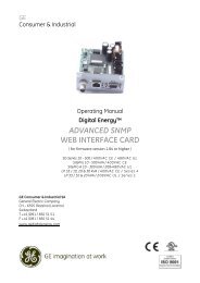
<strong>CEM6</strong>Auto-start digital controller
<strong>CEM6</strong>auto-start digital controllerALARMSCEC6.2CEA6Engine alarms:• High coolant temperature.• Low oil pressure.• Battery charge alternator• Start failure.• Low water level.• Fuel storage.• Overspeed.• Underspeed.• Low battery voltage.• High coolant temperature by sensor.• Low oil pressure by sensor.• Low fuel level by sensor.• Unexpected shutdown.• Stop failure.• Low engine temperature.• Genset voltage drops.• Emergency stop.Generator alarms:• Overload.• Genset voltaje asymmetry.• Maximum genset voltage.• Minimum genset voltage.• Maximum genset frequency.• Minnimum genset frequency.• Erroneus phase sequence of thegenset.• Inverse power.• Shortcircuit.exchancefor new configurations3 Programmable AlarmsThere are three programmable alarmsthat can be associated with enginealarms and be indicated by the LEDsAux1 and Aux2 of the display.When an alarm or warning is detected, the controllerproduces an acoustic signal, at the same time thedigital alarm output (AL) activates and the LED ofRESET button flashes. This status will remain thesame as long as the failure condition continues for aprogrammable period of time.ELECTRONIC publication 10_08
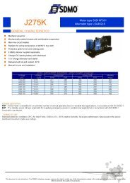
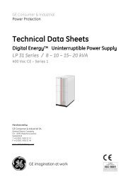
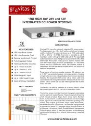
ELECTRONICS<strong>CEM6</strong>auto-start digital controllerGENERAL DESCRIPTIONThe <strong>CEM6</strong> controller unit isa device able to control deoperation, monitoring andprotection of a generating set.The controller unit consists of 2different modules:1. The VISUALIZATION module2. The MEASUREMENTS moduleVISUALIZATION MODULEProvides information about thestatus of the device and, at thesame time, allows the user tointeract with it. It consists on abacklit display and various LEDsfor monitoring the status of thecontroller and buttons that allowthe user to control, program andconfigure the functions of the unit.MEASUREMENTS MODULEControls and monitors the controlboard. It is located in the rear partof the panel, in order to reduce thewiring and to avoid electromagneticdisturbances. Every signal, sensorand actuator is connected to thismodule.The connexion between thevisualization module and themeasurements module is madewith a CAN communication bus. Thisfeature allows the intercommunionof other modules to the maincontroller with a scalability warranty.<strong>CEM6</strong> visualization module1. VISUALIZATION MODULE• Backlit DISPLAY: 4 x 20 digits.• 9 BUTTONS:Only Push Buttons:4 Display buttons for MENU and programming:Confirmation (V), Cancellation (X), Up (+),and Down (-).Push Buttons with LEDs:5 Operation/Command buttons: AUTO, START,STOP, RESET, FUEL Transference.• LEDs for alarms and genset status.Engines Status LEDs:• Engine started.• Preheating.• Engine starting.• Battery charger alternator status.Alarm LEDs:• Fuel storage.• Battery levels.• High temperature.• Starting failure.• Overspeed.• Low oil pressure.• Aux 1 (Free to programme).• Aux 2 (Free to programme).Contactors status LEDs:• M: mains power supply contactor is on.• G: Generator set contactor is on.Multi-languagewww.himoinsa.com
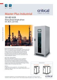
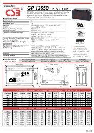
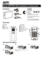
<strong>CEM6</strong>auto-start digital controller2. MEASUREMENTS MODULEReadings of the electric mains supply:• Phase to neutral voltage.• Phase to phase voltage.• Phase amperage.• Frequency.• Real, apparent and reactive powers.• <strong>Power</strong> factor and cos phî.• Instant power (kwH) and historical power (day, month,year). With the programming timer option.Provides the following engine features information:Engine alarm inputs:• Fuel reserve.• Oil pressure.• Coolant temperature.• Coolant level.• Emergency stop (stop button).Analogic engine inputs:• Fuel level.• Oil Pressure.• Coolant Temperature.• Configurable input (i.e. Oil temperature).• Battery charger alternador voltage.Configurable inputs; the measurements device has5 inputs that can be programmed to carry on thefollowing functions:• Rate change notice.• Rate change. (<strong>CEM6</strong> + CEC6.2)• Start disabling.• External start.• Text (<strong>CEM6</strong> + CEC6.2).• Manual override.• 3 programmable alarms.• Parameters auto-programming (S1 - S2)Engine stadistics:• Number of working hours.• Number of starts..Controls functions of the engine:• Pre-heating or Glow Plug.• Stop.• Start.• Coolant heater (<strong>CEM6</strong> + CEC6.2).• Fuel transfer pump.• Alternator excitation.PHG6 measurements moduleSTART OPTION WHENMAINS VOLTAGE DROPS(<strong>CEM6</strong>+CEC6.2).There is an option to convert a generating setwith manual start into an automatic one, thatworks when th e mains voltage drops. This Gensetwill run in a emergency situation and providesa continuous power when there is not supplyfrom the mains.In order to do the change, we must add:1- A battery charger to the manual control panel.2- A new switching control panel, made up bya switching control device (CEC6.2) plus theswitching equipment (i.e. contactors).The M & G symbols in the front panel will onlybe seen “active”, when the switching controller isconnected. M mains power supply contactor isactive, G Generator set contactor is active.The measurements module has outputs whichallow monitoring of the operative conditions ofthe controller:• Engine running (on).• Control board alarm.• 3 programmable outputs which monitor the control boardalarm conditions or the inputs about the engine data.ELECTRONIC publication 10_08
ELECTRONICS<strong>CEM6</strong>auto-start digital controllerVARIOUS FUNCTIONSMAIN CONSTRUCTIVE DATA• Interface CAN/USB. Allows communication withthe control panel in local mode making easierparameter programming, alarm configuration,programmable inputs/outputs.• Interface CAN/RS232 Allows remote communicationwith the control panel through ananalogic modem or a GSM modem.• Positioning system GPS. Allows through theinterface CAN/RS232 to find the exact positionof the genset.• Interface CAN/RS485 allows the communicationwith the control panels systems who workswith protocol MODBUS.• Interface CAN/LAN has the option to connectthe <strong>CEM6</strong> controller with a Ethernet net.• Interface CAN/J1939 allows monitoring of engineswhich are compatible to this protocol.• EJP Functions (Standard for French market)• EJP/T Functions (for French market)• SRC Functions (Genset start and changeovereven with Mains presence through an externalsignal).• Preheating functions of the spark plugs.• Keyboard block Functions.• Decanting fuel Pump Functions command.• Remote monitoring functions for control panelstatus (i.e. Reset status or Automatic Status,etc..)• Possibility to block all the functions after a predefinednumber of working hours, maintenanceor rent.• Automatic test (weekly or daily).• External start and Stop.• Three programmable alarms for different useddefined by the user.• Working temperature: min -20ºC max 80 ºC.• Voltage supply: min. 8V max. 30V.• Maximum amperage consume when rest:100mA.• Starting output amperage: 70A in transitoryregime, 40A during one second. 20 A in regimeof stationary work.• Output amperage when engine stop: (exc./des)70A in transitory regime, 40A during one second.20 A in regime of stationary work.• Pre-heating output amperage: 70A in transitoryregime, 40A during one second. 20 A in regimeof stationary work max 20A.• Alarm contact amperage, Engine working 1A• Max amperage of contactors contact genset/mains 8 A.• Genset frequency status: 30-80 hz.• Pick-up frequency status: 100 Hz at 8 Khz.• Fuel level resistance: 330 Ohmios.• Measure Accuracy: 1%.• Protection rank: IP65 (on control panel).www.himoinsa.com
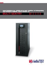
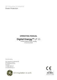
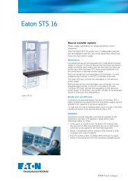
<strong>CEM6</strong>auto-start digital controllerDIMENSIONS AND MECHANIZINGMaximum dimensions:210x160x35,5 mmWeight: 437 gMaximum dimensions:202x117x36 mmWeight: 324 gVisualization module <strong>CEM6</strong>Measurements module PHG6ELECTRONIC publication 10_08
QUICK controllers listELECTRONICSGENERATOR READINGSVoltage among phasesVoltage among phases and neutralAmperageFrequencyApparent power (kVA)Active power (kW)Reactive power (kVAr)<strong>Power</strong> factorM6xxxxxxxx<strong>CEM6</strong>••••••••CEC6.2••••••••CEA6••••••••MAINS READINGSVoltage among phasesVoltage among phase and neutralAmperageFrequencyApparent powerActive powerReactive power<strong>Power</strong> factorxxxxxxxxxxxxxxxx••••xxxx••••••••ENGINE READINGSCoolant temperatureOil pressureFuel level (%)Battery voltageR. P. M.Battery charge alternator voltagexxxxxx• (1)• (1)••••xxxxxx• (1)• (1)••••ENGINE PROTECTIONSHigh water temperatureHigh coolant temperature by sensorLow engine temperature by sensorLow oil pressureLow oil pressure by sensorLow coolant levelUnexpected shutdownFuel storageFuel storage by sensorStop failureBattery voltage failureBattery charge alternator failureOverspeedUnderspeedStart failureEmergency StopPxxPxx•AxxxAPX••P (2)A (3)A (5)P (2)A (3)P•AA (3)•AAPP••xxxxxxxxxxxxxxx•P (2)A (3)A (5)P (2)A (3)P•AA (3)•AAPP••ALTERNATOR PROTECTIONSHigh frequencyLow frequencyHigh voltageLow voltageOver amperageShort-circuitAsymmetry among phasesIncorrect phase sequenceInverse powerOverloadGenset signal droopPxxxxxxxxxxPPPPPPPPPPxP (6)P (6)P (6)P (6)xxP (6)P (6)xxPPPPPPPPPPPxCOUNTERSTotal hour counterPartial hour counterKilowatimeterStarts valid countersStarts failure countersMaintenancexxxxxx••••••••••••••••••• Standardx Not included• OptionalNOTE: All the protection are programmable to carry out“warning” or “engine stop with or without cooling”.www.himoinsa.comwww.himoinsa.com
COMMUNICATIONSRS232RS485J1939ModbusCCLANSoftware for PCAnalogic modemGSM/GPRS modemRemote screenTelesignalM6xxxxxxxxx<strong>CEM6</strong>•••••• (4)•••• (8+4)CEC6.2••x•x• (4)••xCEA6•••••• (4)•••• (8+4)FEATURESAlarms historyExternal startStart inhibitionMains failure startStart under normative EJPKey startPre-heating engine controlGenset contactor activationMain & Genset contactor activationFuel transfer controlEngine temperature controlManual overrideProgrammable alarmsGenset start function in test modeProgrammable outputsMagnetic Pick-up controlMultilingual•xxxx••xxxx(10) / ( • +100)••• (CEC6.2)•x••x••••••••(10)•••xxxx•xxxxxxx•(10) / ( • +100)••••x•x•••••••••SPECIAL FUNCTIONSPositioning GPSSynchronization with mainsMains Synchronism•• (MPS 5.0)• (MPS 5.0)•• (MPS 5.0)• (MPS 5.0)Note: AS5 + CC2configuration, will haveall <strong>CEM6</strong> functionalityplus CEC6.2 mainsreadings.A: Warning. Warning alarm without engine stopP: Alarm with Engine Stop(1) Bulbs installation necessary.(2) Shot protection.(3) Programmable analog. protection. (Depends on bulb installations)(4) Standard when optional of communication is included.(5) Change over activation not allowed before reaching at the temperature level progammed.(6) Only protection with connection to <strong>CEM6</strong>.CEC6.2: available when the controller CEC6.2 is incorporated to the installation.MPS 5.0: available application when the module MPS 5.0 has been incorporated to the panel.QUICK control panels listAvailable Software:ConfigurationM6 <strong>CEM6</strong> CEC6.2 CEA6FUNCTIONALITYAuto-start (Key Start)Auto-startAutomatic Control Panel Without mains controlAutomatic Control Panel With Mains Control(customer change over contactors)Automatic Control Panel With Mains Control(Himoinsa change over contactor with display)Automátic Mains Failure (wall mounted panel)PANEL MODELM6M5AS5AS5AS5+CC2AC5CONTROLLER MODELM6<strong>CEM6</strong><strong>CEM6</strong>**CEA6<strong>CEM6</strong>+CEC6.2CEA6Monitoring** Pre-heating resistance in the Genset and Battery charger in thecontrol panel included.ELECTRONIC publication 10_08Fleet management
ELECTRONICSADVANTAGESHIGH PROTECTIONProtection for the Genset, as well as thedifferent instruments and devices connectedto the genset. Protection for: Overvoltage,Undervoltage, Asymmetry, Overamperage,Overfrequence, underfrequence, Overload,Incorrect genset phase sequence, inverse power,Shortcircuit, High Coolant temperature, Low OilPressure, Overspeed, Underspeed, etc ...COMPLETE HANDFUL OF MEASURESAllows the reading of a handful of measureswith no need of additional instruments orexternal gauges. Apart from protection, offerscontinuously the parameters of genset worksand the digital readings for: Voltage, amperage,frequency, Fuel Level, tachometer, hour counter,power consumption, battery alternator voltage,battery voltage, engine temperature*, oilpressure*, Current power measures, cosineof phi per phase, reading and situation of theprogrammable inputs, Total energy consumptionmeasures ( day, month and year**), Alarmcontrol.GREAT VERSATILITYThese module systems allow the adaptation andgrowing with the market demand and the lawrequirements. The modularity allows to have asharp growth and all-purpose components (evenwith different types of engines). Depends ofthe plate location is possible to obtain differentconfigurations. We start from a standard designand according to the needs it is possible todevelop new extensions.Install only the necessary elements. Basis stockreduction. The same control panel for differentvoltage. Electrical Supply voltage: 12/24V.SIMPLEInstallation is really simple. Wiring system isshortened. Easy to turn a manual device systeminto automatic and vice versa. With one simpleprogramming of the control panel you can adjustmeasures and levels (i.e. automatic filling ofthe fuel tank). <strong>Power</strong> outputs remain protected.More than 64 nodes and more than 1.000 meterswithout signal repeater.FAST PROGRAMMINGPossibility to personalize the features of thecontrol panel to your own application. Apart fromprogramming measure parameters, thresholds,times, alarms, regulations, etc, you can alsoprogram the control panel to stop the genset(with or without cooling time) o simply give you awarning with no stop of the engine.DIFFERENT STARTING MODEManual Start, Automatic Start or free voltagecontactNEW BUSINESS LINESThis control panel allows the creation ofnew business lines and different managingpossibilities since it contains:• Preventive maintenance.• Fungible.• Routes generation.• Genset Global positioning.• Remote control.• Antitheft follow up.• Protection/security.* Only with the corresponding sensors installed ** Only with programming timerspanish english french german italian portuguese polish russian chinesewww.himoinsa.com
FILIALES_ SUBSIDARIESEUROPA / EUROPEHIMOINSA FRANCE (GENELEC S.A.S.)TLF. +33 474 62 65 05 FAX: +33 474 09 07 28HIMOINSA ITALIATLF. +39 0444 58 09 22 FAX: +39 0444 58 12 51HIMOINSA PORTUGALTLF. +351 21 426 65 50 FAX: +351 21 426 65 69HIMOINSA POLSKA SP.ZO.OTLF. +48 22 868 19 18 FAX: +48 22 868 19 31ASIA - PACÍFICO / PACIFIC - ASIAHIMOINSA CHINA CO. LTDTLF. +86 519 8622 66 88 FAX: +86 519 86 22 66 87HIMOINSA FAR EAST PTE LTDTLF. +65 6 265 10 11 FAX: +65 6 265 11 41ORIENTE MEDIO / MIDDLE EASTHIMOINSA MIDDLE EAST FZETLF. +971 4 887 33 15 FAX: +971 4 887 33 18AMERICAHIMOINSA MEXICOTLF. +52 (33) 3675 86 46 FAX: +52 (33) 3914 25 90HIMOINSA POWER SYSTEMS, INC. (USA)TLF. +1 913 495 55 57 FAX: +1 913 495 55 75HIMOINSA PTY (PANAMA)TLF. +507 232 57 41 FAX: +507 232 64 59HIMOINSA CENTRAL_HEAD OFFICEHIMOINSA S.LCtra. Murcia - San Javier, km 23.630730 San Javier (MURCIA) SPAINTLF. +34 968 19 11 28 / +34 902 19 11 28FAX +34 968 19 12 17EXPORT FAX +34 968 19 04 20 /+34 968 33 43 03info@himoinsa.com www.himoinsa.comHIMOINSA CENTRO (Madrid)TLF. +34 91 684 21 06FAX +34 91 684 21 07Centro de Distribución RecambiosSpare Parts Distribution CentreTLF. +34 968 33 40 15FAX +34 968 19 11 53www.himoinsa.com