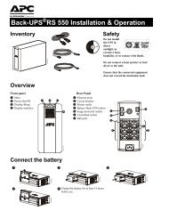
Operation Manual - Critical Power Supplies
Operation Manual - Critical Power Supplies
Operation Manual - Critical Power Supplies

You also want an ePaper? Increase the reach of your titles
YUMPU automatically turns print PDFs into web optimized ePapers that Google loves.
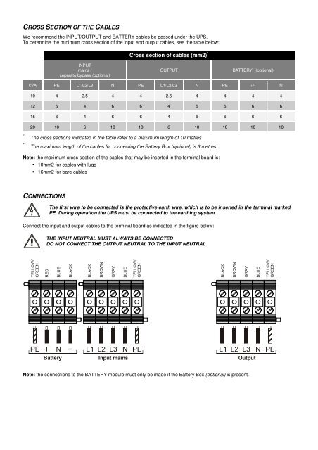
CROSS SECTION OF THE CABLESWe recommend the INPUT/OUTPUT and BATTERY cables be passed under the UPS.To determine the minimum cross section of the input and output cables, see the table below:Cross section of cables (mm2) *INPUTmains /separate bypass (optional)OUTPUTBATTERY ** (optional)kVA PE L1/L2/L3 N PE L1/L2/L3 N PE +/- N10 4 2.5 4 4 2.5 4 4 4 412 6 4 6 6 4 6 6 6 615 6 4 6 6 4 6 6 6 620 10 6 10 10 6 10 10 10 10***The cross sections indicated in the table refer to a maximum length of 10 metresThe maximum length of the cables for connecting the Battery Box (optional) is 3 metresNote: the maximum cross section of the cables that may be inserted in the terminal board is: 10mm2 for cables with lugs 16mm2 for bare cablesCONNECTIONSThe first wire to be connected is the protective earth wire, which is to be inserted in the terminal markedPE. During operation the UPS must be connected to the earthing systemConnect the input and output cables to the terminal board as indicated in the figure below:THE INPUT NEUTRAL MUST ALWAYS BE CONNECTEDDO NOT CONNECT THE OUTPUT NEUTRAL TO THE INPUT NEUTRALNote: the connections to the BATTERY module must only be made if the Battery Box (optional) is present.