Operation Manual - Critical Power Supplies
Operation Manual - Critical Power Supplies
Operation Manual - Critical Power Supplies

Create successful ePaper yourself
Turn your PDF publications into a flip-book with our unique Google optimized e-Paper software.
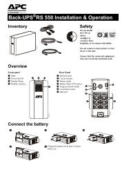
CONNECTIONS OF THE MODEL WITH SEPARATE BYPASSThe first wire to be connected is the protective earth wire, which is to be inserted in the terminal markedPE. During operation the UPS must be connected to the earthing systemConnect the input and output cables to the terminal board as indicated in the figure below:THE INPUT AND BYPASS NEUTRALS MUST ALWAYS BE CONNECTED.THE INPUT AND BYPASS LINES MUST REFER TO THE SAME NEUTRAL POTENTIAL.DO NOT CONNECT THE OUTPUT NEUTRAL TO THE INPUT OR BYPASS NEUTRAL.Note: the connections to the BATTERY module are only to be made if the (optional) Battery Box is present.R.E.P.O.This isolated input is used to turn off the UPS remotely in case of emergency.The UPS is supplied from the factory with the “Remote Emergency <strong>Power</strong> Off” (R.E.P.O.) terminals short-circuited (see "View ofUPS connections” ref.15). If it is to be installed, remove the short-circuit and connect to the normally closed contact of the stopdevice using a cable that provides a double isolation connection.In case of emergency, by activating the stop device, the R.E.P.O. control is opened and the UPS enters stand-by mode (see“USE” section), and powers off the load completely.The R.E.P.O. circuit is self-powered with SELV type circuits. No external power supply voltage is therefore required. When it isclosed (normal condition), a maximum current of 15mA is present.EXTERNAL SYNCThis non-isolated input is used to synchronise the inverter output with an appropriate signal coming from an external source.For the installation:use an isolation transformer with an isolated single-phase output (SELV) comprised in the range 12-24Vac with ≥0.5VA powerconnect the transformer secondary to the "EXTERNAL SYNC" terminal (see "View of UPS connections” ref.19) using adouble isolation cable with a 1mm 2 cross-section. Make sure to respect the polarisation as in the figure below.After installation, enable the control using the configuration software.