Operation Manual - Critical Power Supplies
Operation Manual - Critical Power Supplies
Operation Manual - Critical Power Supplies

You also want an ePaper? Increase the reach of your titles
YUMPU automatically turns print PDFs into web optimized ePapers that Google loves.
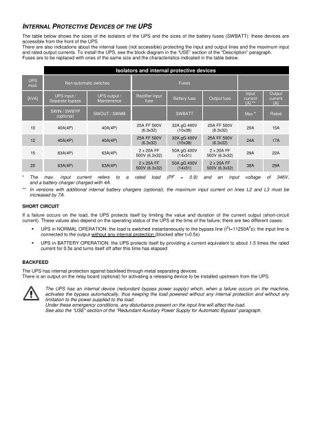
INTERNAL PROTECTIVE DEVICES OF THE UPSThe table below shows the sizes of the isolators of the UPS and the sizes of the battery fuses (SWBATT): these devices areaccessible from the front of the UPS.There are also indications about the internal fuses (not accessible) protecting the input and output lines and the maximum inputand rated output currents. To install the UPS, see the block diagram in the “USE” section of the “Description” paragraph.Fuses are to be replaced with ones of the same size and the characteristics indicated in the table below.Isolators and internal protective devicesUPSmod.Non-automatic switchesFuses[kVA]UPS input /Separate bypassUPS output /MaintenanceRectifier inputfuseBattery fuseOutput fuseInputcurrent[A] **Outputcurrent[A]SWIN / SWBYP(optional)SWOUT / SWMB SWBATT Max * Rated10 40A(4P) 40A(4P)25A FF 500V(6.3x32)32A gG 400V(10x38)25A FF 500V(6.3x32)20A15A12 40A(4P) 40A(4P)25A FF 500V(6.3x32)32A gG 400V(10x38)25A FF 500V(6.3x32)24A17A15 63A(4P) 63A(4P)2 x 20A FF500V (6.3x32)50A gG 400V(14x51)2 x 20A FF500V (6.3x32)29A22A20 63A(4P) 63A(4P)2 x 20A FF500V (6.3x32)50A gG 400V(14x51)2 x 20A FF500V (6.3x32)38A29A* The max. input current refers to a rated load (PF = 0.9) and an input voltage of 346V,and a battery charger charged with 4A.** In versions with additional internal battery chargers (optional), the maximum input current on lines L2 and L3 must beincreased by 7A.SHORT CIRCUITIf a failure occurs on the load, the UPS protects itself by limiting the value and duration of the current output (short-circuitcurrent). These values also depend on the operating status of the UPS at the time of the failure; there are two different cases:UPS in NORMAL OPERATION: the load is switched instantaneously to the bypass line (I 2 t=11250A 2 s): the input line isconnected to the output without any internal protection (blocked after t>0.5s)UPS in BATTERY OPERATION: the UPS protects itself by providing a current equivalent to about 1.5 times the ratedcurrent for 0.5s and turns itself off after this time has elapsedBACKFEEDThe UPS has internal protection against backfeed through metal separating devices.There is an output on the relay board (optional) for activating a releasing device to be installed upstream from the UPS.The UPS has an internal device (redundant bypass power supply) which, when a failure occurs on the machine,activates the bypass automatically, thus keeping the load powered without any internal protection and without anylimitation to the power supplied to the load.Under these emergency conditions, any disturbance present on the input line will affect the load.See also the “USE” section of the “Redundant Auxiliary <strong>Power</strong> Supply for Automatic Bypass” paragraph.