Schebler-P2A-brochure - California Boiler
Schebler-P2A-brochure - California Boiler
Schebler-P2A-brochure - California Boiler

Create successful ePaper yourself
Turn your PDF publications into a flip-book with our unique Google optimized e-Paper software.
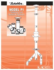
chimney and<br />
exhaust systems<br />
model p2a
LISTINGS<br />
The <strong>Schebler</strong> Model <strong>P2A</strong> chimney and exhaust system is listed by<br />
Underwriters Laboratories Inc. (UL) under file number MH17739<br />
for use as a 1400°F chimney, a 1000°F Building Heating Appliance<br />
Chimney for positive pressures to 60"WC (UL 103) and for Grease<br />
Duct (UL 1978). It also has the Underwriters Laboratories mark<br />
for Canada (cUL).<br />
The system is also approved by the New York City Department of<br />
Buildings for use in New York City. MEA # 227-94-M.<br />
SYSTEM CONCEPT<br />
The Model <strong>P2A</strong> is a modular double wall prefabricated exhaust<br />
system with 2" insulation and 1" air gap for use in venting appliances<br />
that require a positive, neutral or negative draft exhaust system.<br />
Sections are provided in lightweight, easy-to-handle lengths.<br />
Connections are sealed with pressure tight drawbands and high<br />
temperature sealant. Straight sections, expansion joints, tees,<br />
elbows and support devices are offered, allowing a complete<br />
exhaust system to be assembled from standard components.<br />
SURROUNDINGS<br />
The Model <strong>P2A</strong> chimneys are suitable for use with Building Heating<br />
Appliances and other low heat appliances as described in the Chimney<br />
Selection chart of the National Fire Protection Association Standard<br />
Number 211 which produce flue exhaust gases not exceeding 1400°F<br />
under continuous operation or 1800°F intermittent operation. These<br />
chimneys are to be installed as required for metal c himneys. They are<br />
not to be enclosed within combustible construction. An unenclosed<br />
chimney may be placed adjacent to walls of combustible<br />
construction at the clearances specified.<br />
COMPLETE LINE OF FITTINGS AND SIZES AVAILABLE<br />
The Model <strong>P2A</strong> chimney system is available in even and odd diameters<br />
ranging from 5" to 48". A complete line of straight sections, expansion<br />
joints, tees, elbows, rain caps, roof penetration components and<br />
support members are offered. In addition to the standard components<br />
virtually any conceivable fitting is available as a special order item.<br />
MATERIAL AVAILABLE<br />
The Model <strong>P2A</strong> is available in a variety of materials allowing the proper<br />
material selection for your specific application. The standard product<br />
features a 304 stainless steel liner and an aluminized steel outer shell.<br />
For greater corrosion resistance 316 stainless steel is available for the<br />
liner and 304 or 316 stainless steel for the outer shell.<br />
MATERIAL THICKNESS<br />
The standard material thickness for liners is 20 ga. (.036”); for shells it<br />
is 22 ga. (.034”). Fittings larger than 24” diameter utilize 18 ga. (.048”)<br />
on the shell. Pipe diameters 38” and larger utilize 18 ga. (.048”) on the<br />
liners and the shells.<br />
SUPPORT LIMITS<br />
Support plates and wall supports are utilized to support the weight of<br />
the chimney and to provide a fixed point to allow proper operation of<br />
expansion joints. In horizontal runs supports should be placed adjacent<br />
to fittings that are not otherwise supported. See the individual part<br />
description for allowable support charts.<br />
TESTS PERFORMED<br />
The Model <strong>P2A</strong> has endured rigorous tests by Underwriters Laboratories.<br />
Just a few of the tests performed are:<br />
• Structural Tests The support plates and wall supports have been<br />
physically tested to carry a load 4 times that allowed by our listing.<br />
• Wind Load Tests Loads equivalent to 110 mph wind have been<br />
applied to the chimney with acceptable results.<br />
• Skin Temperature Rise Tests The chimney has been subjected<br />
to a series of burn tests at temperatures up to 1800°F. The purpose<br />
of these tests is to determine safe clearances from the chimney wall<br />
to combustible materials.<br />
• Rain Tests The rain caps have been tested to ensure that an<br />
unsatisfactory amount of water does not enter the rain cap.<br />
SCHEBLER VALUE<br />
• Fast Project Completion<br />
- 2-week lead time (vs. industry standard 3-6 weeks)<br />
- Trouble-free installation / detailed instructions<br />
- No on-site welding<br />
• Maximum Strength / Long Life<br />
- Unmatched dimensional accuracy for secure joint<br />
connections<br />
- Fully welded liners and shells<br />
- Unequalled support limits<br />
• Complete System Design<br />
- CAD drawings<br />
- 3D design solutions<br />
- Complete BOM<br />
- System sizing<br />
• Special Fittings<br />
For most applications the standard 304SS inner, aluminized outer<br />
material selection is sufficient. Under the following conditions you<br />
may consider the use of alternate materials:<br />
• <strong>Boiler</strong>s firing oils heavier than #2 use 316SS for the inner shell.<br />
• Exterior installations which are not easily accessible for periodic<br />
painting you should consider a 304SS outer shell which will require<br />
no maintenance.<br />
2
OPERATING TEMPERATURES AND<br />
CLEARANCES CHART<br />
The Model <strong>P2A</strong> has been tested and listed for continuous use at both<br />
1000°F and 1400°F as well as for use as grease duct at the following<br />
clearances to combustible materials. The clearances shown are from<br />
the shell to combustibles.<br />
<strong>P2A</strong> Clearance to Combustibles<br />
Section Inside 1000˚F (560˚C) 1400˚F (760˚C)<br />
Diameter Chimney* Chimney<br />
5"-6" 1" (25mm) 2" (51mm)<br />
7"-16" 2" (51mm) 3" (76mm)<br />
17"-20" 3" (76mm) 4" (102mm)<br />
21"-24" 4" (102mm) 5" (127mm)<br />
25"-28" 5" (127mm) 6" (152mm)<br />
29"-32" 6" (152mm) 7" (178mm)<br />
33"-36" 7" (178mm) 8" (203mm)<br />
37"-40" 8" (203mm) 9" (229mm)<br />
41"-48" 11" (279mm) 12" (305mm)<br />
*Building Heating Appliance Chimney<br />
Section Inside Diameter Grease Duct<br />
5"-6" 2" (51mm)<br />
7"-12" 3" (76mm)<br />
13"-16" 4" (102mm)<br />
17"-20" 5" (127mm)<br />
21"-24" 6" (152mm)<br />
25"-30" 7" (178mm)<br />
31"-34" 8" (203mm)<br />
35"-38" 9" (305mm)<br />
39"-42" 10" (254mm)<br />
43"-38" 11" (279mm)<br />
JOINT ASSEMBLY<br />
Note: Wipe inner bands and flanges clean prior to assembly.<br />
1. Apply continuous bead of proper sealant covering one of<br />
the ½” flange of the two parts being joined.<br />
2. Fully fill the vee groove of the inner band with proper sealant.<br />
3. Join the flanged ends of the two sections together.<br />
4. Install the inner band around the flanges and tighten<br />
the screws.<br />
5. Tap around the inner band with a rawhide mallet and retighten<br />
the screws to ensure a tight joint.<br />
6. Install the provided insulation strips over the inner band.<br />
7. Place the outer band over the space between the outer shells<br />
of the adjoining sections and tighten the screws. For outdoor<br />
installations, apply a bead of S600 sealant in the groove at the<br />
upper end of the outer band.<br />
SEALANT<br />
<strong>Schebler</strong> offers three types of sealant, S600, S2000, and S2001. The<br />
S600 is used for applications with flue gas temperatures up to 600°F<br />
(315˚C). This includes most boilers and water heaters. The S2000 is<br />
used for grease duct systems. S2001 is used for installations operating<br />
under positive pressure, such as generator exhaust.<br />
Clearance to non-combustible materials for all diameters and<br />
applications is 1" (25mm).<br />
PART NUMBERS<br />
All standard parts manufactured by <strong>Schebler</strong> are identified by a part<br />
number which describes their make up and function.<br />
The part numbers are made up as follows:<br />
1. The first series is the model<br />
designation, PA, P1, P2, <strong>P2A</strong>,<br />
P4 or SW.<br />
2. This is followed by the part name.<br />
For example 47S, 90T and CC.<br />
3. Next is the part’s internal diameter<br />
in inches, such as 06, 12, 24.<br />
4. Last is the liner/shell material<br />
designation.<br />
For example the part number for an 8"<br />
ID, Model PA, 47" long straight section<br />
with a 304 stainless steel liner and<br />
aluminized steel shell is: PA47S08A.<br />
Code<br />
Liner / Shell<br />
Material<br />
A 304 / Aluminized<br />
B 316 / Aluminized<br />
C 304 / 304 or all 304<br />
D 304 / 316<br />
E 316 / 316 or all 316<br />
F Galvanized<br />
G Aluminized<br />
H Painted Carbon Steel<br />
N 304 / 430<br />
P 316 / 430<br />
Q 430<br />
S 316 / 304<br />
3<br />
STEP 1 STEP 2 STEP 3<br />
STEP 4-5 STEP 6 STEP 7
SYSTEM COMPONENTS<br />
custom dimensions are available to suit your needs in even and odd sizes<br />
adapter kit (flanged)<br />
Part No. BKF<br />
The Adapter Kit (Flanged) is<br />
used for securing pipe to a<br />
flanged appliance outlet. Beam<br />
clamps are provided for<br />
connection of the flanges, or<br />
the flange can be drilled in the<br />
field to match the appliance.<br />
Includes 1 inner band and 1 seal<br />
ring to cover the gap between<br />
the inner and outer shells.<br />
STRAIGHT SECTION<br />
Part No. 18S, 29S,<br />
47S and 59S<br />
Standard lengths are as follows:<br />
Diameter 5" - 7" is 18", 29"<br />
and 47"<br />
Diameter 8" - 24" is 18", 29",<br />
47" and 59<br />
Diameter 25" - 48" is 18", 29"<br />
and 47"<br />
Custom parts can be manufactured<br />
to any length over 8".<br />
Includes 1 inner and 1 outer band.<br />
Adjustable length<br />
Part No. 18AL, 22AL,<br />
30AL and 45AL<br />
The Adjustable Length is used<br />
to provide adjustment during<br />
installation as well as<br />
compensate for thermal<br />
expansion between fixed points.<br />
The adjustment in length<br />
available for each part is<br />
as follows:<br />
18AL = 14" to 17"<br />
22AL = 16" to 21"<br />
30AL = 20" to 29"<br />
45AL = 27 ½" to 44"<br />
BELLOWS section<br />
Part No. BS<br />
The Bellows Section is<br />
designed to compensate for<br />
thermal expansion, up to 3".<br />
This part is recom mended<br />
for diesel engine and turbine<br />
exhaust systems.<br />
Includes liner, shell, and<br />
1 inner band.<br />
Includes 1 inner and 1 outer band.<br />
adapter kit (raw)<br />
Part No. bkr<br />
The Adapter Kit (Raw) is<br />
used for securing pipe to an<br />
unflanged appliance outlet.<br />
ABRUPT INCREASER<br />
Part No. AI<br />
The Abrupt Increaser is<br />
used to connect two sections<br />
of different diameters in<br />
a shorter space than a<br />
tapered increaser.<br />
Includes 1 inner band and<br />
1 seal ring to cover the gap<br />
between the inner and<br />
outer shells.<br />
variable length<br />
section<br />
Part No. 18VS, 29VS<br />
and VS<br />
The Variable Section adjusts<br />
to provide a fixed odd length<br />
between two sections. The<br />
minimum length is 5", the<br />
maximum is 18", 29" or 40".<br />
This part does not provide for<br />
thermal expansion.<br />
Includes 1 inner band of<br />
larger and smaller sizes<br />
and 1 seal ring.<br />
Includes liner, shell, slip joint,<br />
and 1 inner band.<br />
4
TAPERED INCREASER<br />
Part No. TI<br />
The Tapered Increaser is used when a change in pipe<br />
diameter is required.<br />
Includes 1 inner and 1 outer band of both smaller<br />
and larger size.<br />
Part No. TI<br />
I.D. A B A B A B A B<br />
6" 8" 15" 10" 18" 12" 21" 14" 24"<br />
8" 10" 15" 12" 18" 14" 21" 16" 24"<br />
10" 12" 15" 14" 18" 16" 21" 18" 24"<br />
12" 14" 15" 16" 18" 18" 21" 20" 24"<br />
14" 16" 15" 18" 18" 20" 21" 22" 24"<br />
16" 18" 15" 20" 18" 22" 21" 24" 24"<br />
18" 20" 15" 22" 18" 24" 21" 26" 24"<br />
20" 22" 15" 24" 18" 26" 21" 28" 24"<br />
22" 24" 15" 26" 18" 28" 21" 30" 24"<br />
24" 26" 15" 28" 18" 30" 21" 32" 24"<br />
26" 28" 15" 30" 18" 32" 21" 34" 24"<br />
28" 30" 15" 32" 18" 34" 21" 36" 24"<br />
30" 32" 15" 34" 18" 36" 21" 38" 24"<br />
32" 34" 15" 36" 18" 38" 21" 40" 24"<br />
34" 36" 15" 38" 18" 40" 21" 42" 24"<br />
36" 38" 15" 40" 18" 42" 21" 44" 24"<br />
38" 40" 15" 42" 18" 44" 21" 46" 24"<br />
40" 42" 15" 44" 18" 46" 21" 48" 24"<br />
42" 44" 15" 46" 18" 48" 21" ~ ~<br />
44" 46" 15" 48" 18" ~ ~ ~ ~<br />
46" 48" 15" ~ ~ ~ ~ ~ ~<br />
48" ~ ~ ~ ~ ~ ~ ~ ~<br />
Available in odd sizes.<br />
Call for odd diameter taper increaser information.<br />
REDUCING<br />
45˚ lateral tee<br />
Part No. R45LT<br />
The Reducing 45° Lateral Tee is used for low flow resistance<br />
entry into a stack or breeching when the stack or breeching is a<br />
larger size. Specify size of branch required.<br />
Includes 1 each inner band and outer band for larger and<br />
smaller opening.<br />
45˚ lateral tee<br />
Part No. 45LT<br />
The 45˚ Lateral Tee is used for<br />
low flow resistance entry into a<br />
stack or breeching.<br />
Includes 2 inner bands and<br />
2 outer bands.<br />
Note: Grease tees available<br />
1 ½" containment dam located<br />
at one opening.<br />
Part No. 45LT / R45LT<br />
I.D. A B C<br />
5-6" 7" 26" 19"<br />
7-8" 7 3 ⁄ 8" 28 3 ⁄ 4" 21 3 ⁄ 8"<br />
9-10" 7 3 ⁄ 4" 31 1 ⁄ 2" 23 3 ⁄ 4"<br />
11-12" 8 1 ⁄ 4" 34 1 ⁄ 2" 26 1 ⁄ 4"<br />
13-14" 8 5 ⁄ 8" 37 1 ⁄ 4" 28 5 ⁄ 8"<br />
15-16" 9 1 ⁄ 16" 40 1 ⁄ 8" 31 1 ⁄ 16"<br />
17-18" 9 1 ⁄ 2" 43" 33 1 ⁄ 2"<br />
19-20" 9 7 ⁄ 8" 45 3 ⁄ 4" 35 7 ⁄ 8"<br />
21-22" 10 5 ⁄ 16" 48 5 ⁄ 8" 38 5 ⁄ 16"<br />
23-24" 10 3 ⁄ 4" 51 1 ⁄ 2" 40 3 ⁄ 4"<br />
25-26" 11 1 ⁄ 8" 54 1 ⁄ 4" 43 1 ⁄ 8"<br />
27-28" 11 9 ⁄ 16" 57 1 ⁄ 8" 45 9 ⁄ 16"<br />
29-30" 12" 60" 48"<br />
31-32" 12 3 ⁄ 8" 62 3 ⁄ 4" 50 3 ⁄ 8"<br />
33-34" 12 3 ⁄ 4" 65 1 ⁄ 2" 52 3 ⁄ 4"<br />
35-36" 13 3 ⁄ 16" 68 3 ⁄ 8" 55 3 ⁄ 16"<br />
37-38" 13 5 ⁄ 8" 71 1 ⁄ 4" 57 5 ⁄ 8"<br />
39-40" 14" 74" 60"<br />
41-42" 14 7 ⁄ 16" 76 7 ⁄ 8" 62 7 ⁄ 16"<br />
43-44" 14 7 ⁄ 8" 79 3 ⁄ 4" 64 7 ⁄ 8"<br />
45-46" 15 1 ⁄ 4" 82 1 ⁄ 2" 67 1 ⁄ 4"<br />
47-48" 15 11 ⁄ 16" 85 3 ⁄ 8" 69 11 ⁄ 16"<br />
5
SYSTEM COMPONENTS<br />
custom dimensions are available to suit your needs in even and odd sizes<br />
90˚ tee<br />
Part No. 90T<br />
The 90˚ Tee is used to join<br />
horizontal and vertical<br />
sections, as well as to provide<br />
for connection of drain or<br />
inspection fittings. Use<br />
either the drain tee cap<br />
or the end cap for closure<br />
of the unused opening.<br />
90˚ boot tee<br />
Part No. BT<br />
The 90˚ Boot Tee is used<br />
to join horizontal and vertical<br />
sections with lower resistance<br />
as well as to provide for<br />
connection of drain or<br />
inspection fittings. Use<br />
either the drain tee cap<br />
or the end cap for closure<br />
of the unused opening.<br />
90˚ Wye<br />
Part No. 90Y<br />
The 90˚ Wye is used for joining<br />
runs where low flow resistance<br />
is desired. All openings must be<br />
the same size. For connection<br />
to smaller diameter sections use<br />
the tapered or abrupt increasers.<br />
END CAP<br />
Part No. EC<br />
The End Cap is used to close<br />
an unused tee opening and to<br />
provide a means of accessing<br />
the interior of the system for<br />
inspection and cleaning.<br />
Includes 2 inner bands and<br />
2 outer bands.<br />
Note: Grease tees available<br />
1 ½" containment dam located<br />
at one opening.<br />
Includes 2 inner bands and<br />
2 outer bands.<br />
Includes 2 inner bands and<br />
2 outer bands.<br />
Note: Grease wye available<br />
1 ½" containment dam located<br />
at one opening.<br />
Includes 1 inner band.<br />
reducing 90˚ tee<br />
Part No. R90T<br />
The Reducing 90° Tee is used<br />
to join horizontal and vertical<br />
sections of different sizes, as<br />
well as provide for connection<br />
to drain or inspection fittings.<br />
Use either the drain tee cap or<br />
the end cap for closure of the<br />
unused opening. Specify size of<br />
branch required.<br />
Includes 1 each inner band<br />
and outer band for larger and<br />
smaller opening.<br />
Part No. 90T /<br />
R90T / BT<br />
I.D.<br />
A<br />
5-6" 10 ½"<br />
7-8" 11 ½"<br />
9-10" 12 ½"<br />
11-12" 13 ½"<br />
13-14" 14 ½"<br />
15-16" 15 ½"<br />
17-18" 16 ½"<br />
19-20" 17 ½"<br />
21-22" 18 ½"<br />
23-24" 19 ½"<br />
25-26" 20 ½"<br />
27-28" 21 ½"<br />
29-30" 22 ½"<br />
31-32" 23 ½"<br />
33-34" 24 ½"<br />
35-36" 25 ½"<br />
37-38" 26 ½"<br />
39-40" 27 ½"<br />
41-42" 28 ½"<br />
43-44" 29 ½"<br />
45-46" 30 ½"<br />
47-48" 31 ½"<br />
Part No. 90Y<br />
I.D. A B<br />
5-6" 10 ½" 7"<br />
7-8" 11 ½" 7 13 ⁄ 32"<br />
9-10" 12 ½" 7 13 ⁄ 16"<br />
11-12" 13 ½" 8 7 ⁄ 32"<br />
13-14" 14 ½" 8 5 ⁄ 8"<br />
15-16" 15 ½" 9 1 ⁄ 16"<br />
17-18" 16 ½" 9 7 ⁄ 16"<br />
19-20" 17 ½" 9 7 ⁄ 8"<br />
21-22" 18 ½" 10 9 ⁄ 32"<br />
23-24" 19 ½" 10 23 ⁄ 32"<br />
25-26" 20 ½" 11 1 ⁄ 8"<br />
27-28" 21 ½" 11 17 ⁄ 32"<br />
29-30" 22 ½" 11 31 ⁄ 32"<br />
31-32" 23 ½" 12 3 ⁄ 8"<br />
33-34" 24 ½" 12 25 ⁄ 32"<br />
35-36" 25 ½" 13 3 ⁄ 16"<br />
37-38" 26 ½" 13 11 ⁄ 16"<br />
39-40" 27 ½" 14 1 ⁄ 32"<br />
41-42" 28 ½" 14 15 ⁄ 32"<br />
43-44" 29 ½" 14 27 ⁄ 32"<br />
45-46" 30 ½" 15 1 ⁄ 4"<br />
DRAIN TEE CAP<br />
Part No. DTC<br />
The Drain Tee Cap is used to<br />
close an unused tee opening<br />
and to provide a drain at the<br />
base of a vertical chimney.<br />
Includes 1 inner band.<br />
47-48" 31 ½" 15 11 ⁄ 16"<br />
6
90˚ elbow<br />
Part No. 90L<br />
The 90° Elbow is used when<br />
making a 90° directional<br />
change. The 90° elbow is<br />
available in sizes 5" through 24".<br />
For a 90° directional change in<br />
diameters from 25" through 48"<br />
use two 45° elbows.<br />
Includes 1 inner and 1 outer band.<br />
45˚ elbow<br />
Part No. 45L<br />
The 45° Elbow is used when a vertical or<br />
horizontal direction change of 45° is desired.<br />
Includes 1 inner and 1 outer band.<br />
30˚ elbow<br />
Part No. 30L<br />
The 30° Elbow is used when a vertical or<br />
horizontal direction change of 30° is desired.<br />
Includes 1 inner and 1 outer band.<br />
Part No. 90L<br />
I.D. A<br />
5-6" 13 ½"<br />
7-8" 15 ½"<br />
9-10" 17 ½"<br />
11-12" 19 ½"<br />
13-14" 21 ½"<br />
15-16" 23 ½"<br />
17-18" 25 ½"<br />
19-20" 27 ½"<br />
21-22" 29 ½"<br />
23-24" 31 ½"<br />
Part No. 45L<br />
I.D. A B C D<br />
5-6" 7" 9 29 ⁄ 32" 23 29 ⁄ 32" 16 29 ⁄ 32"<br />
7-8" 7 3 ⁄ 8" 10 7 ⁄ 16" 25 3 ⁄ 16" 17 13 ⁄ 16"<br />
9-10" 7 3 ⁄ 16" 11 3 ⁄ 64" 26 43 ⁄ 64" 18 55 ⁄ 64"<br />
11-12" 8 1 ⁄ 4" 11 43 ⁄ 64" 28 11 ⁄ 64" 19 59 ⁄ 64"<br />
13-14" 8 5 ⁄ 8" 12 13 ⁄ 64" 29 29 ⁄ 64" 20 53 ⁄ 64"<br />
15-16" 9 1 ⁄ 16" 12 13 ⁄ 16" 30 15 ⁄ 16" 21 7 ⁄ 8"<br />
17-18" 9 1 ⁄ 2" 13 7 ⁄ 16" 32 7 ⁄ 16" 22 15 ⁄ 16"<br />
19-20" 9 7 ⁄ 8" 13 31 ⁄ 32" 33 23 ⁄ 32" 23 27 ⁄ 32"<br />
21-22" 10 5 ⁄ 16" 14 37 ⁄ 64" 35 13 ⁄ 64" 24 57 ⁄ 64"<br />
23-24" 10 3 ⁄ 4" 15 13 ⁄ 64" 36 45 ⁄ 64" 25 61 ⁄ 64"<br />
25-26" 11 1 ⁄ 8" 15 47 ⁄ 64" 37 63 ⁄ 64" 26 55 ⁄ 64 "<br />
27-28" 11 9 ⁄ 16" 16 23 ⁄ 64" 39 31 ⁄ 64" 27 59 ⁄ 64 "<br />
29-30" 11 15 ⁄ 16" 16 7 ⁄ 8" 40 3 ⁄ 4" 28 13 ⁄ 16 "<br />
31-32" 12 3 ⁄ 8" 17 1 ⁄ 2" 42 1 ⁄ 4" 29 7 ⁄ 8"<br />
33-34" 12 3 ⁄ 4" 18 1 ⁄ 32" 43 17 ⁄ 32" 30 25 ⁄ 32"<br />
35-36" 13 3 ⁄ 16" 18 21 ⁄ 32" 45 1 ⁄ 32" 31 27 ⁄ 32"<br />
37-38" 13 5 ⁄ 8" 19 17 ⁄ 64" 46 33 ⁄ 64" 32 57 ⁄ 64"<br />
39-40" 14" 19 51 ⁄ 64" 47 51 ⁄ 64" 33 51 ⁄ 64"<br />
41-42" 14 7 ⁄ 16" 20 27 ⁄ 64" 49 19 ⁄ 64" 34 55 ⁄ 64"<br />
43-44" 14 7 ⁄ 8" 21 1 ⁄ 32" 50 25 ⁄ 32" 35 29 ⁄ 64"<br />
45-46" 15 1 ⁄ 4" 21 9 ⁄ 16" 52 1 ⁄ 16" 36 13 ⁄ 16"<br />
47-48" 15 11 ⁄ 16" 22 3 ⁄ 16" 53 9 ⁄ 16" 37 7 ⁄ 8"<br />
7<br />
Part No. 30L<br />
I.D. A B C D<br />
5-6" 6 1 ⁄ 8" 6 1 ⁄ 8" 22 55 ⁄ 64" 13 13 ⁄ 64"<br />
7-8" 6 3 ⁄ 8" 6 3 ⁄ 8" 23 51 ⁄ 64" 13 47 ⁄ 64"<br />
9-10" 6 5 ⁄ 8" 6 5 ⁄ 8" 24 23 ⁄ 32" 14 9 ⁄ 32"<br />
11-12" 6 15 ⁄ 16" 6 15 ⁄ 16" 25 57 ⁄ 64" 14 61 ⁄ 64"<br />
13-14" 7 3 ⁄ 16" 7 3 ⁄ 16" 26 53 ⁄ 64" 15 31 ⁄ 64"<br />
15-16" 7 7 ⁄ 16" 7 7 ⁄ 16" 27 3 ⁄ 4" 16 1 ⁄ 32"<br />
17-18" 7 3 ⁄ 4" 7 3 ⁄ 4" 28 59 ⁄ 64" 16 45 ⁄ 64"<br />
19-20" 8" 8" 29 55 ⁄ 64" 17 15 ⁄ 64"<br />
21-22" 8 1 ⁄ 4" 8 1 ⁄ 4" 30 51 ⁄ 64" 17 23 ⁄ 32"<br />
23-24" 8 1 ⁄ 2" 8 1 ⁄ 2" 31 23 ⁄ 32" 18 5 ⁄ 16"<br />
25-26" 8 3 ⁄ 4" 8 3 ⁄ 4" 32 21 ⁄ 32" 18 55 ⁄ 64 "<br />
27-28" 9 1 ⁄ 16" 9 1 ⁄ 16" 33 53 ⁄ 64" 19 17 ⁄ 32 "<br />
29-30" 9 5 ⁄ 16" 9 5 ⁄ 16" 34 3 ⁄ 4" 20 1 ⁄ 16 "<br />
31-32" 9 9 ⁄ 16" 9 9 ⁄ 16" 35 11 ⁄ 16" 20 39 ⁄ 64"<br />
33-34" 9 7 ⁄ 8" 9 7 ⁄ 8" 36 55 ⁄ 64" 21 9 ⁄ 32"<br />
35-36" 10 1 ⁄ 8" 10 1 ⁄ 8" 37 25 ⁄ 32" 21 13 ⁄ 16"<br />
37-38" 10 3 ⁄ 8" 10 3 ⁄ 8" 38 23 ⁄ 32" 22 23 ⁄ 64"<br />
39-40" 10 5 ⁄ 8" 10 5 ⁄ 8" 39 21 ⁄ 32" 22 57 ⁄ 64"<br />
41-42" 10 15 ⁄ 16" 10 15 ⁄ 16" 40 13 ⁄ 16" 23 9 ⁄ 16"<br />
43-44" 11 3 ⁄ 16" 11 3 ⁄ 16" 41 3 ⁄ 4" 24 7 ⁄ 64"<br />
45-46" 11 1 ⁄ 2" 11 1 ⁄ 2" 42 59 ⁄ 64" 24 25 ⁄ 32"<br />
47-48" 11 3 ⁄ 4" 11 3 ⁄ 4" 43 55 ⁄ 64" 25 5 ⁄ 16"
SYSTEM COMPONENTS<br />
custom dimensions are available to suit your needs in even and odd sizes<br />
DRAIN SECTION<br />
Part No. DS<br />
The Drain Section is used<br />
to drain rain water and<br />
condensation from within the<br />
stack. The NPT nipple should be<br />
connected to a suitable drain.<br />
Includes 1 inner and 1 outer band.<br />
horizonTal DRAIN<br />
Part No. HD<br />
The Horizontal Drain is used<br />
to drain rain water and<br />
condensation from within the<br />
stack. The NPT nipple should be<br />
connected to a suitable drain.<br />
Includes 1 inner and 1 outer band.<br />
BASE DRAIN SECTION<br />
Part No. BD<br />
The Base Drain Section<br />
provides a bottom closure<br />
and drain attachment for<br />
base supported chimneys.<br />
Includes 1 inner and 1 outer band.<br />
NOZZLE SECTION<br />
Part No. NS<br />
The Nozzle Section includes a 1"<br />
NPT connection to be used as a<br />
test port.<br />
Includes 1 inner and 1 outer band.<br />
FLASHING<br />
Part No. FL<br />
The Flashing is used in<br />
conjunction with the rain<br />
collar to seal roof penetrations.<br />
This part is designed for flat<br />
roofs. Custom pitched flashings<br />
are available upon request.<br />
SQUARE SIZE = PIPE ID + 21”<br />
RAIN COLLAR<br />
Part No. RC<br />
The Rain Collar is used in<br />
conjunction with the flashing<br />
to seal roof penetrations.<br />
ID + 6 /<br />
8<br />
INSULATED THIMBLE<br />
Part No. IT<br />
The Insulated Thimble is<br />
used when penetrating a<br />
combustible wall or roof. This<br />
part is designed for flat roofs.<br />
Custom pitched thimbles are<br />
available upon request.<br />
RAIN CAP<br />
Part No. CC<br />
The Rain Cap is used at stack<br />
terminations to prevent water<br />
from entering the flue. A drain<br />
should be used at the base of<br />
stacks to drain off water that<br />
may be blown into the flue.<br />
Includes 1 inner band and<br />
1 closure ring to seal outer<br />
shell joint.<br />
flip top cap<br />
Part No. FTC<br />
The Flip Top Cap is used in<br />
generator systems when the cap<br />
remains closed until pressure<br />
opens the cap.<br />
1 16<br />
PIPE ID + 12”<br />
Includes 1 inner band and<br />
1 closure ring to seal outer<br />
shell joint.<br />
TOP SECTION<br />
Part No. TS<br />
The Top Section is used to<br />
protect the insulating space<br />
between the inner and outer<br />
shells when an open<br />
termination is required.<br />
A drain should be used at the<br />
base of stacks to drain off water<br />
that enters the system.<br />
Includes 1 inner band and<br />
1 closure ring to seal outer<br />
shell joint.<br />
FAN ADAPTER<br />
Part No. FA<br />
The Fan Adapter is used to<br />
attach grease duct to an exhaust<br />
fan or kitchen hood.<br />
Includes 1 inner and 1 outer band.<br />
Note: Plenum boxes available for<br />
multiple fan systems.
exit cone<br />
Part No. EXC<br />
The Exit Cone is used to<br />
increase the flue gas velocity<br />
exiting the stack. A drain<br />
should be used at the base<br />
of stacks to remove any<br />
water that enters the stack.<br />
Includes 1 inner band and<br />
1 closure ring to seal outer<br />
shell joint.<br />
horizontal<br />
termination<br />
Part No. HT<br />
The Horizontal Termination<br />
is used when the stack<br />
terminates in a horizontal<br />
position. Birdscreen covers the<br />
opening to prevent any birds or<br />
rodents from entering.<br />
Includes 1 inner and 1 outer band.<br />
SUPPORT PLATE<br />
Part No. SP<br />
The Support Plate is the<br />
primary load carrying member<br />
of the chimney assembly. This<br />
part is designed to support<br />
(B) (See Chart Below) feet of<br />
vertical chimney section as<br />
well as provide fixed points<br />
in breeching runs.<br />
Includes 1 inner band and<br />
2 half outer bands.<br />
WALL SUPPORT<br />
Part No. WS<br />
The Wall Support is used to<br />
provide chimney support along<br />
a wall. The wall support will<br />
maintain the required clearance<br />
to combustible structures when<br />
properly installed and can<br />
support (C) (See Chart Below)<br />
feet of vertical chimney.<br />
Includes 1 inner band and<br />
2 half outer bands.<br />
Note: This part must be<br />
placed at the connection<br />
of two flue sections.<br />
Note: This part must be<br />
placed at the connection<br />
of two flue sections.<br />
Part No. EXC<br />
I.D. A B<br />
6" 4 7 ⁄ 8" 5 3 ⁄ 8"<br />
8" 6 1 ⁄ 2" 6 1 ⁄ 8"<br />
10" 8 1 ⁄ 8" 6 3 ⁄ 4"<br />
12" 9 3 ⁄ 4" 7 1 ⁄ 2"<br />
14" 11 3 ⁄ 8" 8 1 ⁄ 8"<br />
16" 13 1 ⁄ 8" 8 7 ⁄ 8"<br />
18" 14 3 ⁄ 4" 9 1 ⁄ 2"<br />
20" 16 3 ⁄ 8" 10 1 ⁄ 4"<br />
22" 18" 10 7 ⁄ 8"<br />
24" 19 5 ⁄ 8" 11 5 ⁄ 8"<br />
26" 21 1 ⁄ 4" 12 1 ⁄ 4"<br />
28" 22 7 ⁄ 8" 13"<br />
30" 24 1 ⁄ 2" 13 5 ⁄ 8"<br />
32" 26 1 ⁄ 8" 14 3 ⁄ 8"<br />
34" 27 3 ⁄ 4" 15"<br />
36" 29 1 ⁄ 2" 15 3 ⁄ 4"<br />
38" 31" 16 3 ⁄ 8"<br />
40" 32 5 ⁄ 8" 17 1 ⁄ 8"<br />
42" 34 1 ⁄ 4" 17 3 ⁄ 4"<br />
44" 35 7 ⁄ 8" 18 1 ⁄ 2"<br />
46" 37 1 ⁄ 2" 19 1 ⁄ 8"<br />
48" 39 1 ⁄ 4" 19 3 ⁄ 4"<br />
guy section<br />
Part No. GS<br />
The Guy Section is to be used<br />
when the chimney extends<br />
beyond the vertical limits above<br />
the roof line. The guy section<br />
should be connected to guy<br />
wires or a rigid guying structure.<br />
Includes 1 inner band and<br />
2 half outer bands.<br />
Note: This part must be<br />
placed at the connection<br />
of two flue sections.<br />
Part No. SP<br />
I.D. A B(FT)<br />
5-6" 19 3 ⁄ 16" 190'<br />
7-8" 21 3 ⁄ 16" 183'<br />
9-10" 23 3 ⁄ 16" 177'<br />
11-12" 25 3 ⁄ 16" 170'<br />
13-14" 27 3 ⁄ 16" 163'<br />
15-16" 29 3 ⁄ 16" 157'<br />
17-18" 31 3 ⁄ 16" 150'<br />
19-20" 34 3 ⁄ 16" 143'<br />
21-22" 36 3 ⁄ 16" 137'<br />
23-24" 38 3 ⁄ 16" 130'<br />
25-26" 40 3 ⁄ 16" 123'<br />
27-28" 42 3 ⁄ 16" 117'<br />
29-30" 44 3 ⁄ 16" 110'<br />
31-32" 46 3 ⁄ 16" 103'<br />
33-34" 48 3 ⁄ 16" 97'<br />
35-36" 50 3 ⁄ 16" 90'<br />
37-38" 52 3 ⁄ 16" 83'<br />
39-40" 54 3 ⁄ 16" 77'<br />
41-42" 56 3 ⁄ 16" 70'<br />
43-44" 58 3 ⁄ 16" 63'<br />
45-46" 60 3 ⁄ 16" 57'<br />
Part No. WS<br />
I.D. A B C(FT)<br />
5-6" 8" 10 5 ⁄ 16" 120'<br />
7-8" 10" 12 5 ⁄ 8" 117'<br />
9-10" 11" 13 11 ⁄ 16" 113'<br />
11-12" 12" 15 1 ⁄ 16" 110'<br />
13-14" 13" 16 3 ⁄ 8" 107'<br />
15-16" 14" 17 3 ⁄ 4" 103'<br />
17-18" 16" 19 3 ⁄ 4" 100'<br />
19-20" 17" 21 7 ⁄ 16" 97'<br />
21-22" 19" 23 1 ⁄ 2" 93'<br />
23-24" 20" 24 13 ⁄ 16" 90'<br />
25-26" 22" 26 13 ⁄ 16" 87'<br />
27-28" 23" 28 3 ⁄ 16" 83'<br />
29-30" 25" 30 3 ⁄ 16" 80'<br />
31-32" 26" 31 9 ⁄ 16" 77'<br />
33-34" 28" 33 9 ⁄ 16" 73'<br />
35-36" 29" 34 7 ⁄ 8" 70'<br />
37-38" 31" 36 7 ⁄ 8" 67'<br />
39-40" 32" 38 1 ⁄ 4" 63'<br />
41-42" 36" 41 5 ⁄ 8" 60'<br />
43-44" 37" 42 15 ⁄ 16" 57'<br />
45-46" 38" 44 5 ⁄ 16" 53'<br />
47-48" 62 3 ⁄ 16" 50'<br />
47-48" 39" 45 5 ⁄ 8" 50'<br />
9
SYSTEM COMPONENTS<br />
custom dimensions are available to suit your needs in even and odd sizes<br />
full ring<br />
Part No. FR<br />
The Full Ring is used to guide<br />
horizontal and vertical runs.<br />
The part is simply bolted<br />
around the outer shell then<br />
rigidly connected to the<br />
building structure.<br />
FLOOR/ROOF GUIDE<br />
Part No. FRG<br />
The Floor/Roof Guide is used<br />
at the penetration of floors and<br />
roofs to guide the chimney. This<br />
part is designed to absorb lateral<br />
loads only. It will not support<br />
vertical chimney sections.<br />
wall GUIDE<br />
Part No. WG<br />
The Wall Guide is used to<br />
guide long vertical runs that<br />
are placed adjacent to walls.<br />
This part will maintain proper<br />
clearance to combustibles<br />
when properly installed.<br />
PRESSURE RELIEF<br />
VALVE<br />
Part No. PRV<br />
The Pressure Relief Valve is<br />
used in generator exhaust<br />
systems to prevent damage<br />
resulting in the ignition of<br />
unburned fuel. This component<br />
complies with NFPA 37.<br />
Valves are set to 1 PSI.<br />
half ring<br />
Part No. HR<br />
The Half Ring is used to<br />
support long horizontal runs,<br />
placed under the flue<br />
and then supported by<br />
rods connecting to the<br />
building structure.<br />
Part No. FRG<br />
I.D.<br />
A<br />
5-6" 11 3 ⁄ 8"<br />
7-8" 12 3 ⁄ 8"<br />
9-10" 13 3 ⁄ 8"<br />
11-12" 14 3 ⁄ 8"<br />
13-14" 15 3 ⁄ 8"<br />
15-16" 16 3 ⁄ 8"<br />
17-18" 17 3 ⁄ 8"<br />
19-20" 18 3 ⁄ 8"<br />
21-22" 19 3 ⁄ 8"<br />
23-24" 20 3 ⁄ 8"<br />
25-26" 21 3 ⁄ 8"<br />
27-28" 22 3 ⁄ 8"<br />
29-30" 23 3 ⁄ 8"<br />
31-32" 24 3 ⁄ 8"<br />
33-34" 25 3 ⁄ 8"<br />
35-36" 26 3 ⁄ 8"<br />
37-38" 27 3 ⁄ 8"<br />
39-40" 28 3 ⁄ 8"<br />
41-42" 29 3 ⁄ 8"<br />
43-44" 30 3 ⁄ 8"<br />
45-46" 31 3 ⁄ 8"<br />
47-48" 32 3 ⁄ 8"<br />
Part No. WG<br />
I.D. A B<br />
5-6" 8" 7"<br />
7-8" 10" 7 5 ⁄ 8"<br />
9-10" 11" 7 13 ⁄ 16"<br />
11-12" 12" 8 1 ⁄ 2"<br />
13-14" 13" 8 5 ⁄ 8"<br />
15-16" 14" 9 "<br />
17-18" 16" 9 7 ⁄ 16"<br />
19-20" 17" 9 3 ⁄ 4"<br />
21-22" 19" 10 1 ⁄ 4"<br />
23-24" 20" 10 9 ⁄ 16"<br />
25-26" 22" 11 1 ⁄ 8"<br />
27-28" 23" 11 5 ⁄ 16"<br />
29-30" 25" 11 7 ⁄ 8"<br />
31-32" 26" 12 1 ⁄ 8"<br />
33-34" 28" 12 11 ⁄ 16"<br />
35-36" 29" 12 15 ⁄ 16"<br />
37-38" 31" 13 1 ⁄ 2"<br />
39-40" 32" 13 11 ⁄ 16"<br />
41-42" 36" 14 5 ⁄ 16"<br />
43-44" 37" 14 1 ⁄ 2"<br />
45-46" 38" 15 1 ⁄ 16"<br />
47-48" 39" 15 5 ⁄ 16"<br />
SQUARE-TO-ROUND<br />
TRANSITIONS<br />
The Square-to-Round<br />
Transitions are used when<br />
connecting to appliances with<br />
square or rectangular outlets.<br />
The base can be raw for field<br />
welding or flanged for field<br />
drilling and bolting.<br />
COLD-FACE TEmpERATURE<br />
300˚ F<br />
250˚ F<br />
200˚ F<br />
150˚ F<br />
100˚ F<br />
50˚ F<br />
outer shell temp chart<br />
0˚ F<br />
350˚ F 500˚ F 1000˚ F 1400˚ F<br />
MID-FLUE TEmpERATURE<br />
10
<strong>P2A</strong> weight chart<br />
Part Description Part No. 6"<br />
14" to 17" Adjustable 18AL 18 lbs.<br />
16" to 21" Adjustable 22AL 26 lbs.<br />
20" to 29" Adjustable 30AL 26 lbs.<br />
27 ½" to 44" Adjustable 45AL 37 lbs.<br />
29" Straight Section 29S 24 lbs.<br />
30 Degree Elbow 30L 12 lbs.<br />
45 Degree Elbow 45L 13 lbs.<br />
45 Degree Tee 45LT 29 lbs.<br />
47" Straight Section 47S 37 lbs.<br />
59" Straight Section 59S -<br />
90 Degree Elbow 90L 19 lbs.<br />
90 Degree Grease Tee 90GT 23 lbs.<br />
90 Degree Wye 90Y 20 lbs.<br />
90 Degree Tee 90T 22 lbs.<br />
Abrupt Increaser AI 7 lbs.<br />
Base Drain BD 18 lbs.<br />
Bellows Section BS 19 lbs.<br />
<strong>Boiler</strong> Kits<br />
BKF, BKR 7 lbs.<br />
Drain Section DS 17 lbs.<br />
Drain Tee Cap DTC 6 lbs.<br />
End Cap EC 5 lbs.<br />
Fan Adapter FA 7 lbs.<br />
Flashing FL 11 lbs.<br />
Floor/Roof Guide FRG 11 lbs.<br />
Full Ring FR 5 lbs.<br />
Guy Section GS 16 lbs.<br />
Half Ring HR 3 lbs.<br />
Horizontal Drain HD 17 lbs.<br />
Nozzle Section NS 17 lbs.<br />
Rain Cap CC 10 lbs.<br />
Rain Collar RC 5 lbs.<br />
Support Plate SP 31 lbs.<br />
Tapered Increaser TI 20 lbs.<br />
Top Section TS 5 lbs.<br />
Variable Section VS 37 lbs.<br />
Wall Guide WG 13 lbs.<br />
Wall Support WS 49 lbs.<br />
Inside Diameter (Inches)<br />
8" 10" 12" 14" 16" 18" 20" 22" 24" 26" 28" 30" 32" 34" 36" 38" 40" 42" 44" 46" 48"<br />
21 25 29 32 36 39 43 47 50 54 58 61 77 81 85 103 108 113 118 123 128<br />
25 29 33 38 42 46 50 55 59 63 67 72 90 95 100 121 126 132 138 144 150<br />
32 37 42 48 54 59 64 70 76 81 86 92 117 123 130 155 163 170 178 185 193<br />
44 52 60 68 76 83 91 99 107 115 122 130 167 176 185 220 230 241 252 262 273<br />
29 34 39 44 49 54 59 64 69 74 79 84 107 113 119 142 149 156 163 170 176<br />
14 17 20 24 27 31 34 38 42 46 51 55 71 77 83 102 110 117 125 134 142<br />
16 19 23 27 32 36 41 46 52 57 63 69 89 97 105 130 140 151 161 172 184<br />
38 48 60 73 87 102 118 136 155 175 196 219 294 324 355 434 472 512 554 597 642<br />
44 52 60 68 76 83 91 99 107 115 122 130 167 176 185 220 230 241 252 262 273<br />
55 65 75 85 95 104 114 124 134 - - - - - - - - - - - -<br />
25 33 42 52 62 74 87 101 116 - - - - - - - - - - - -<br />
30 37 44 52 61 71 82 92 104 116 129 142 189 206 225 274 297 320 345 370 396<br />
25 31 38 45 52 61 69 79 88 99 109 121 160 175 190 233 252 272 292 313 335<br />
29 36 43 51 60 70 80 90 102 114 126 139 185 202 221 269 291 314 338 363 388<br />
9 10 12 14 15 17 19 20 22 23 25 27 28 30 32 40 42 44 46 48 50<br />
21 24 28 31 34 37 41 44 47 51 54 57 66 69 73 85 89 93 97 101 105<br />
23 27 31 35 39 43 47 51 55 59 62 67 84 88 93 112 117 123 128 134 139<br />
9 10 12 14 15 17 19 20 22 23 25 27 28 30 32 40 42 44 46 48 50<br />
20 24 27 31 34 38 41 45 48 52 55 59 74 78 82 99 104 109 113 118 123<br />
7 8 10 11 13 14 16 18 20 23 25 27 30 33 43 56 60 65 70 75 80<br />
6 7 9 10 12 13 15 17 19 22 24 26 29 32 42 55 59 64 69 74 79<br />
8 10 11 13 15 16 18 20 21 23 24 26 28 29 31 39 41 43 45 47 49<br />
12 13 15 16 18 19 21 22 24 25 27 29 30 32 34 35 37 39 40 42 44<br />
12 15 16 17 18 19 24 25 27 27 30 30 32 33 34 35 36 38 39 41 42<br />
6 9 10 11 12 13 18 19 21 21 24 24 26 27 28 29 30 32 33 35 36<br />
19 22 24 27 30 33 35 38 41 44 47 49 52 55 58 64 67 70 73 76 79<br />
3 5 5 6 6 7 9 10 11 11 12 12 13 14 14 15 15 16 17 18 18<br />
20 24 27 31 34 38 41 45 48 52 55 59 74 78 82 99 104 109 113 118 123<br />
20 24 27 31 34 38 41 45 48 52 55 59 74 78 82 99 104 109 113 118 123<br />
13 15 18 21 24 27 30 34 37 41 45 49 56 61 69 78 84 91 98 105 111<br />
6 6 7 7 8 8 9 9 10 10 11 11 12 12 13 13 14 14 15 15 16<br />
36 42 47 53 58 64 70 76 99 107 114 122 130 138 146 186 196 206 217 227 238<br />
24 28 32 36 40 44 48 53 57 61 65 69 87 92 96 116 122 128 133 139 144<br />
6 7 8 9 10 11 12 12 13 14 15 16 17 18 22 26 27 28 29 31 32<br />
44 52 60 68 76 83 91 99 107 115 122 130 167 176 185 220 230 241 252 262 273<br />
16 20 22 24 27 30 36 40 42 45 48 51 53 57 60 64 64 73 75 78 81<br />
60 70 81 92 103 118 132 149 179 199 215 236 254 277 295 350 372 412 435 459 482<br />
All weights shown above are actual weights, for shipping weights multiply by 1.25<br />
sample specification - model p2A<br />
The factory built modular chimney shall be laboratory tested and listed in<br />
accordance with Underwriters Laboratories Standard UL 103 for use with<br />
building heating equipment burning gas, solid or liquid fuels with flue gases<br />
not exceeding 1400°F continuous operations and 1800°F intermittent<br />
operation. It shall also be tested and listed for use as a grease duct in<br />
accordance with UL 1978. Sections shall bear the UL listing mark and the<br />
cUL listing mark for Canada. Sections shall be sealed with banded flanges<br />
utilizing joint sealant supplied by the manufacturer for the specific application.<br />
Inner shell material shall be type 304 stainless steel for natural gas and number<br />
2 oil fired appliances, type 316 stainless steel for coal, number 4 and number<br />
6 oil fired appliances. Inner shell thickness shall be .036" for 5" to 36" diameter<br />
systems and .048" for 37" to 48" diameter systems. All inner shell seams shall<br />
be full penetration welded the entire length of the pipe section. Riveted, tack or<br />
spot welded seams are not permitted.<br />
Outer shell material shall be aluminized steel with a thickness of .034" for 5"<br />
to 36" diameter systems and .052" for 37" to 48" systems.<br />
(Outer shell thickness of optional type 304 or 316 stainless steel shall be .030" for<br />
5" to 36" diameter systems and .048" for 37" to 48" diameter systems). All outer<br />
shell seams shall be full penetration welded the entire length of the pipe section.<br />
Riveted, tack or spot welded seams are not permitted.<br />
Between the inner and outer shells there shall be a minimum 1" air gap and 2"<br />
of 1600°F rated low conductivity ceramic fiber insulation. The insulation is to be<br />
securely attached to the inner shell with steel straps and insulating pins welded<br />
to the inner shell. Stainless steel centering clips shall be welded to the outer<br />
shell to maintain the 3" spacing and ensure concentricity of the shells.<br />
Breeching and chimney sections, when installed according to manufacturer’s<br />
instructions, shall comply with national safety standards and building<br />
codes. Stacks terminating above a roof must terminate as required by<br />
code or NFPA 211.<br />
Chimney sections exposed to atmospheric conditions shall be protected<br />
by a minimum of one base coat and one finish coat of heat resistant paint after<br />
installation. Outer shells of type 304 or 316 stainless steel need not be painted.<br />
11
MODEL <strong>P2A</strong> STANDARD 5-YEAR WARRANTY<br />
The <strong>Schebler</strong> Model <strong>P2A</strong> Chimney, where installed according to<br />
manufacturer’s installation instructions, is warranted by the <strong>Schebler</strong><br />
Company for a period of five (5) years from date of system start-up,<br />
against defects in material and workmanship of the product for parts<br />
only Any defective part in the product will, at <strong>Schebler</strong>’s option, either be<br />
repaired or replaced. Should the part be returned, the owner must pay all<br />
transportation charges. The repaired or replacement part will, in turn, be<br />
shipped by <strong>Schebler</strong> to the owner, freight prepaid. The warranty on any<br />
repaired or replacement part shall be for a duration of time no longer<br />
than the remaining or unexpired term of the original warranty.<br />
This warranty does not cover labor or other service charges<br />
incurred by the owner, nor any parts not manufactured by The<br />
<strong>Schebler</strong> Company, or any other components that are not part<br />
of the Model <strong>P2A</strong> Chimney Systems.<br />
This limited warranty is extended to the purchaser subject to the<br />
satisfaction of the following conditions:<br />
1. Generally accepted engineering practices have been followed<br />
to determine that sizing and material specifications are suitable<br />
for the application and environment involved.<br />
2. The undamaged components have been correctly installed<br />
in accordance with the installation instructions published by<br />
The <strong>Schebler</strong> Company at the time of shipment.<br />
The <strong>Schebler</strong> Company assumes no liability for incidental or<br />
consequential damages of any kind or for any damages resulting in whole<br />
or part from misuse, improper installation, or inadequate maintenance<br />
of the system or component part thereof. This warranty is in lieu of all<br />
other express warranties or guarantees of any kind. All implied warranties,<br />
including merchantability and fitness, are limited to the duration of the<br />
express warranty contained herein. The <strong>Schebler</strong> Company neither<br />
assumes nor does it authorize any other person to assume on its<br />
behalf any other liability in connection with the sale of its products.<br />
2" ceramic fiber insulation<br />
1" air gap<br />
Inner V-band<br />
Outer band<br />
Model <strong>P2A</strong> spacer clip<br />
Inner liner 1/2" rolled flange<br />
Model <strong>P2A</strong> spacer clip<br />
Inner liner<br />
Outer shell<br />
MODEL <strong>P2A</strong> EXTENDED 10-YEAR WARRANTY<br />
The <strong>Schebler</strong> Company warrants owners of its Model <strong>P2A</strong> Chimney<br />
against defects in material and workmanship in normal use for ten (10)<br />
years from the date of delivery to the construction site when installed,<br />
maintained and used as part of a <strong>Schebler</strong> Model <strong>P2A</strong> Chimney<br />
System and in accordance with The <strong>Schebler</strong> Company specifications.<br />
The <strong>Schebler</strong> Company further warrants any portion of the chimney<br />
system repaired or replaced under this warranty for the remainder of<br />
the original warranty period.<br />
This warranty is limited to repair or replacement of the product plus<br />
shipping cost to the failure location. This warranty does not cover any<br />
labor costs for removal or replacement of the defective product nor<br />
does this warranty cover any system components not furnished by<br />
The <strong>Schebler</strong> Company and installed as part of the system.<br />
This limited warranty is extended to the purchaser subject to the<br />
satisfaction of the following conditions:<br />
1. System sizing and design has been performed by <strong>Schebler</strong><br />
personnel and design parameters provided to The <strong>Schebler</strong><br />
Company by the responsible engineer were and are accurately<br />
representative of the operating conditions.<br />
2. The undamaged components have been correctly installed in<br />
accordance with system design and sizing as performed by<br />
<strong>Schebler</strong> and installation instructions published by The<br />
<strong>Schebler</strong> Company at the time of shipment.<br />
3. Proper precautions have been taken to insure that appliance air is<br />
free of solvent or refrigerant vapors or any halogenated compound<br />
which may cause acid condensate to form within the chimney.<br />
4. The <strong>Schebler</strong> Company has supplied the entire chimney or exhaust<br />
system from the appliance outlet to the termination of the stack.<br />
5. Prior to start-up and thereafter, exposed aluminized steel surfaces<br />
are protected with a minimum of one base coat of primer and<br />
one finish coat of heat resistant paint at all times.<br />
The <strong>Schebler</strong> Company assumes no liability for incidental or<br />
consequential damages of any kind or for any damages resulting<br />
in whole or part from misuse, improper installation, or inadequate<br />
maintenance of the system or component part thereof. This warranty<br />
is in lieu of all other express warranties or guarantees of any kind.<br />
All implied warranties, including merchantability and fitness, are<br />
limited to the duration of the express warranty contained herein.<br />
The <strong>Schebler</strong> Company neither assumes nor does it authorize any<br />
other person to assume on its behalf any other liability in connection<br />
with the sale of its products.<br />
P 800.391.0009 • 563.359.0110<br />
5665 Fenno Rd<br />
Bettendorf, Iowa 52722<br />
www.scheblerchimney.com<br />
© 2011 <strong>Schebler</strong> Chimney Systems. All Rights Reserved. AMG - 03.11