![Unit 5. Switches and VLANs [PDF]](https://img.yumpu.com/34422504/1/500x640/unit-5-switches-and-vlans-pdf.jpg)
Unit 5. Switches and VLANs [PDF]
Unit 5. Switches and VLANs [PDF]
Unit 5. Switches and VLANs [PDF]

Create successful ePaper yourself
Turn your PDF publications into a flip-book with our unique Google optimized e-Paper software.
Aims<br />
The aims of this unit are to:<br />
• Underst<strong>and</strong>s the usage of switches <strong>and</strong> <strong>VLANs</strong> in network design.<br />
• Configure basic information on a Cisco switch.<br />
• Configure Cisco switches for <strong>VLANs</strong>.<br />
<strong>Unit</strong> 5: <strong>Switches</strong> <strong>and</strong> <strong>VLANs</strong> 81
Introduction<br />
This unit outlines the importance of network switches, especially as the improve network<br />
security, <strong>and</strong> also allow for faster communications than traditional connection devices,<br />
such as hubs. A switch enhances the security of a network as it allows for a direct<br />
connection between two devices, where no other devices on the switch can listen to the<br />
connection. They also enhance security as a switch can be programmed to create a virtual<br />
LAN (vLAN), where nodes which connect to one vLAN can be isolated from other<br />
vLANs. Thus a device may connect to the same network switch, but connect to a<br />
different network than other devices which also connect to the same switch. A vLAN can<br />
span access one or more switches, which aids the configuration of the network.<br />
vLANs<br />
vLANs are a new technology, which uses software to define a broadcast domain, rather<br />
than any physical connections. In a vLAN a message transmitted by one node is only<br />
received by other nodes with a certain criteria to be in the domain. It is made by logically<br />
grouping two or more nodes <strong>and</strong> a vLAN-initialized switching device, such as intelligent<br />
switches (which use the MAC address to forward data frames) or routers (which use the<br />
network address to route data packets). The important concept with vLANs is that the<br />
domain is defined by software, <strong>and</strong> not by physical connections.<br />
There are two methods that can define the logical grouping of nodes within a vLAN:<br />
• Implicit tagging. This uses a special tagging field which is inserted into the data<br />
frames or within data packets. It can be based upon the MAC address, a switch port<br />
number, protocol, or another parameter by which nodes can be logically grouped.<br />
The main problem with implicit tagging is that different vendors create different tags<br />
which make vendor interoperability difficult. This is known as frame filtering.<br />
• Explicit tagging. This uses an additional field in the data frame or packet header.<br />
This can also lead to incompatibility problems, as different vendor equipment may<br />
not be able to read or process the additional field. This is known as frame<br />
identification.<br />
It is thus difficult to create truly compatible vLANs until st<strong>and</strong>ards for implicit <strong>and</strong><br />
explicit tags are st<strong>and</strong>ardized. One example of creating a vLAN is to map ports of a<br />
switch to create two or more virtual LANs. For example, a switch could connect to two<br />
servers <strong>and</strong> 16 clients. The switch could be configured so that eight of the clients<br />
connected to one server through a vLAN, <strong>and</strong> the other eight onto the other server. This<br />
setup is configured in software, <strong>and</strong> not by the physical connection of the network.<br />
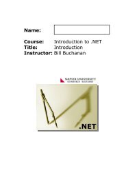
Figure 4 shows a possible implementation where nodes 1 to 8 create a vLAN through the<br />
switch with SERVER1, <strong>and</strong> nodes 9 to 16 create a vLAN with SERVER2. The switch<br />
would map ports to create the vLANs, where the two networks are now independent<br />
broadcast domains (network segments), <strong>and</strong> will only receive the broadcasts from each of<br />
their virtual LANs. Normally a switch would connect any one of its ports to another<br />
port, <strong>and</strong> allow simultaneous connection. In this case, the switch allows for multiple<br />
connections onto a segment. Now, with the vLAN, data frames transmitted on one<br />
network segment will stay within that segment <strong>and</strong> are not transmitted to the other<br />
vLAN.<br />
82 Computer Networks – CO33006
Figure 1<br />
Creating a vLAN by mapping<br />
ports of a switch<br />
SERVER1<br />
SERVER2<br />
Switch<br />
(creates a vLAN for for the<br />
two networks)<br />
vLAN1<br />
vLAN2<br />
1 8 9 16<br />
Advantages of vLANs<br />
The main advantages of using vLAN are:<br />
• Creation of virtual networks. Just as many organizations build open-plan offices<br />
which can be changed when required, vLANs can be used to reconfigure the logical<br />
connections to a network without actually having to physically move any of the<br />
resources. This is especially useful in creating workgroups where users share the same<br />
resources, such as databases <strong>and</strong> disk storage.<br />
• Ease of administration. vLANs allow networks to be easily configured, possibly at a<br />
distance from the configured networks. In the past reconfiguration has meant<br />
recabling <strong>and</strong> the movement of networked resources. With vLANs the resources can<br />
be configured with software to setup the required network connections.<br />
• Improved b<strong>and</strong>width usage. Normally users who work in a similar area share<br />
resources. This is typically known as a workgroup. If workgroups can be isolated from<br />
other workgroups then traffic which stays within each of the workgroups does not<br />
affect other workgroups. A vLAN utilizes this concept by grouping users who share<br />
information <strong>and</strong> configuring the networked resources around them. This makes<br />
much better usage of b<strong>and</strong>width than workgroup users who span network segments.<br />
The amount of broadcast traffic on the whole network is also reduced, as broadcasts<br />
can be isolated within each of the workgroups. A typical drain on network b<strong>and</strong>width<br />
is when network servers broadcast their services at regular intervals (in Novell<br />
NetWare this can be once every minute, <strong>and</strong> is known as the Service Advertising<br />
Protocol). With vLANs these broadcasts would be contained within each of the<br />
vLANs that the server is connected to.<br />
• Microsegmentation. This involves dividing a network into smaller segments, which<br />
will increase the overall b<strong>and</strong>width available to networked devices.<br />
• Enhanced security. vLANs help to isolate network traffic so that traffic which stays<br />
within a vLAN will not be transmitted outside it. Thus it is difficult for an external<br />
<strong>Unit</strong> 5: <strong>Switches</strong> <strong>and</strong> <strong>VLANs</strong> 83
user to ‘listen’ to any of the data that is transmitted across the vLAN, unless they can<br />
get access to one of the ports of the vLAN device. This can be difficult as this would<br />
require a physical connection, <strong>and</strong> increases the chances of the external user being<br />
caught ‘spying’ on the network.<br />
• Relocate servers into secured locations. vLANs allows for servers to be put in a<br />
physical location in which they cannot be tampered with. This will typically be in a<br />
secure room, which is under lock <strong>and</strong> key. The vLAN can be used to map hosts to<br />
servers.<br />
• Easy creation of IP subnets. vLANs allow the creation of IP subnets, which are not<br />
dependent on the physical location of a node. Users can also remain part of a subnet,<br />
even if they move their computer.<br />
vLAN structure<br />
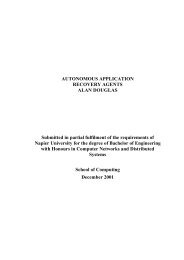
A vLAN can be created by connecting workgroups by a common backbone, where<br />
broadcast frames are switched only between ports within the same vLAN. This requires<br />
port-mapping to establish the broadcast domain, which is based on a port ID, MAC<br />
address, protocol or application. Each frame is tagged with a VLAN ID. Figure 5<br />
illustrates that switches are one of the core components of a VLAN. Each switch is<br />
intelligent enough to decide whether to forward data frame, based on VLAN metrics<br />
(such as port ID, MAC address or network address), <strong>and</strong> to communicate this<br />
information to other switches <strong>and</strong> routers within the network. The switching is based on<br />
frame filtering or frame identification.<br />
Most early vLANs were based on frame filters, but the IEEE 802.1q vLAN st<strong>and</strong>ard<br />
is based on frame tagging, as this allows for scaleable networks. With frame tagging, each<br />
frame has a uniquely assigned user-defined ID. A unique identifier in the header of each<br />
frame is forwarded throughout the network backbone (vertical cabling), as illustrated in<br />
Figure <strong>5.</strong> Each switch then reads the identifier, <strong>and</strong> if the frame is part of a network<br />
which it controls, the switch removes the identifier before the frame is transmitted to the<br />
target node (horizontal cabling). As the switching occurs at the data link layer, there is<br />
not a great processing time overhead.<br />
Switch<br />
Switch<br />
VLAN_A<br />
VLAN_B<br />
Figure 2<br />
vLANs using a<br />
backbone <strong>and</strong><br />
switches<br />
Switch<br />
Switch<br />
84 Computer Networks – CO33006
VLAN broadcasts<br />
vLANs rely on broadcasts to the virtual network, but they are constrained within the<br />
virtual network, <strong>and</strong> thus are not transmitted to other virtual networks. This should<br />
reduce the amount of overall network broadcasts (especially from broadcast storms). The<br />
broadcast domain can be reduced by limiting the number of switched ports which<br />
connect to a specific vLAN. The smaller the grouping, the lower the broadcast effect.<br />
vLAN’s <strong>and</strong> security<br />
vLANs increase security of data as transmitted data is confined to the vLAN in which it is<br />
transmitted. These provide natural firewalls, in which external users cannot gain access to<br />
the data within a vLAN. This security occurs, as switch ports can be grouped based on<br />
the application type <strong>and</strong> access privileges. Restricted applications <strong>and</strong> resources can be<br />
placed in a secured VLAN group.<br />
The two types of vLANs are:<br />
• Static vLANs. These are ports on a switch that are statically assigned to a VLAN.<br />
These remain permanently assigned, until they are changed by the administrator.<br />
Static vLANs are secure <strong>and</strong> easy to configure, <strong>and</strong> are useful where vLANs are fairly<br />
well defined.<br />
• Dynamic <strong>VLANs</strong>. These are ports on a switch which automatically determine their<br />
VLAN assignments. This is achieved with intelligent management software, using<br />
MAC addresses, logical addressing, or the protocol type of the data packets. Initially,<br />
where a node connects to the switch, the switch detects its MAC address entry in the<br />
VLAN management database <strong>and</strong> dynamically configures the port with the<br />
corresponding VLAN configuration. The advantage of dynamic vLANs is that they<br />
require less setup from the administrator (but the database must be initially created).<br />
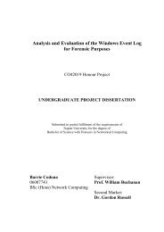
The broadcast domain in a vLAN is defined by each vLAN, as illustrated in Figure 6. A<br />
node broadcasting into the vLAN will only be transmitted to nodes within its vLAN.<br />
Nodes not connected to the same vLAN, even although they connect to the same switch<br />
as the broadcasting node, will not receive the broadcast. The only way for nodes to<br />
intercommunicate across differing vLANs is to be routed through a router (as illustrated<br />
in Figure 7).<br />
<strong>Unit</strong> 5: <strong>Switches</strong> <strong>and</strong> <strong>VLANs</strong> 85
VLAN_A<br />
VLAN_B<br />
DATA FRAME<br />
Switch<br />
Switch<br />
DATA FRAME<br />
VLAN_B<br />
Switch<br />
Switch<br />
Backbone<br />
DATA FRAME<br />
Figure 3 vLANs using frame tagging<br />
Broadcast domain<br />
Broadcast domain<br />
Switch<br />
VLAN1<br />
Figure 4<br />
VLAN2<br />
Broadcast domains for vLANs<br />
Note that a broadcast domain extends the full length of the vLAN, <strong>and</strong> not onto other<br />
vLANs. A router does not forward broadcasts, thus the vLAN is isolated from other<br />
networks. The router provides intercommunicate between vLANs, <strong>and</strong> security is<br />
enhanced by implement security restrictions on the ports of the router.<br />
Broadcast domains<br />
VLAN broadcast domains<br />
As previously mentioned the broadcast domain is important, as nodes use it to determine<br />
the MAC addresses of nodes within their vLAN. In Figure 8, a node on VLAN1 could<br />
only communicate with a node on VLAN2 if would use the network address of the node<br />
on VLAN2. For example if Node A communicates with Node B, it would broadcast an<br />
ARP request into its vLAN for the MAC address of Node B, which would return it back<br />
86 Computer Networks – CO33006
to the vLAN. Node A can then communicate with Node B, as it uses the MAC address<br />
of Node B, <strong>and</strong> its network layer address. If Node A wishes to communicate with Node<br />
C, it will send out an ARP request to the port on the router to which it connects to (its<br />
gateway). This port will respond back with its MAC address. Node A will then send out a<br />
data frame with the MAC address of the gateway, <strong>and</strong> the destination address of Node C.<br />
The router will then forward it onto the port which has Node C connected to it, <strong>and</strong><br />
changes the destination MAC address to the MAC address of Node C (if it already knows<br />
it, else it would initially send out an ARP request for it). The router will generally test the<br />
incoming data frame for security purposes, <strong>and</strong> will only forward it if Node A is allowed<br />
to communicate with Node C (allowing for certain conditions).<br />
VLAN1<br />
VLAN2<br />
A<br />
B<br />
C<br />
Switch<br />
VLAN’s<br />
intercommunicate<br />
through a router<br />
Router<br />
Security is set<br />
on the ports<br />
on the router<br />
Figure 5<br />
Broadcast domains for vLANs<br />
<strong>Unit</strong> 5: <strong>Switches</strong> <strong>and</strong> <strong>VLANs</strong> 87
Activity <strong>5.</strong>1: Programming Cisco switches<br />
The following sections relate to the programming a Cisco switch. For this purpose a<br />
special emulator has been developed. This is shown in Figure 9.<br />
Figure 9: Cisco 1900/2800 switch emulator<br />
Showing version of switch<br />
Initially you will be in the user executive (Exec) mode, <strong>and</strong> the functions that you can<br />
perform are limited.<br />
1 Use the comm<strong>and</strong> to view the comm<strong>and</strong>s in this mode.<br />
What comm<strong>and</strong>s are available in Exec mode<br />
2 Use the show version comm<strong>and</strong> to show the current operating system details.<br />
How many Ethernet ports does the switch have<br />
What is the MAC address of the switch<br />
Setting host <strong>and</strong> IP information<br />
Next go into the privileged executive mode:<br />
88 Computer Networks – CO33006
1 Go into the privileged mode by typing enable.<br />
How does the prompt change<br />
2 Use the comm<strong>and</strong> to view the comm<strong>and</strong>s in this mode.<br />
What comm<strong>and</strong>s are available in Privileged Exec mode<br />
3 Configure the device using by typing config t.<br />
How does the prompt change<br />
4 Set the hostname by typing hostname myhost.<br />
5 Go back to the user executive mode with the comm<strong>and</strong> exit.<br />
6 Show the IP parameters of the switch with the comm<strong>and</strong> show ip interface.<br />
What are the parameters displayed<br />
7 Go back to configuration mode with config t.<br />
8 Configure the VLAN with the interface vlan 1 comm<strong>and</strong>.<br />
9 Set the IP address <strong>and</strong> subnet mask with the comm<strong>and</strong> ip address 192.168.0.1<br />
25<strong>5.</strong>25<strong>5.</strong>25<strong>5.</strong>0.<br />
10 Go back to privileged mode with exit.<br />
11 Show the IP parameters again with show ip interface.<br />
What are the parameters displayed<br />
12 From the config mode, set the gateway address to 192.168.0.2, the domain-name is<br />
mycomp.com, the name-server to 192.168.0.10, using:<br />
(config)# ip default-gateway 192.168.0.2<br />
(config)# ip domain-name mycomp.com<br />
(config)# ip name-server 192.168.0.10<br />
14 Show the main system configuration with show running-config.<br />
What are the parameters displayed<br />
Setting telnet interface<br />
It is possible to remotely log into the switch over the network using TELNET. To do this<br />
the following is achieved:<br />
1 Go to the Executive Privileged mode (that is, with the # prompt).<br />
2 Go to the configuration mode (that is, with the (config) # prompt).<br />
3 Use the line vty 0 15 to create up to 16 possible TELNET sessions.<br />
4 Use the password fred to define the password as fred<br />
5 Exit from the config mode with end.<br />
6 Show the current running configuration with show running-config.<br />
Has the configuration been updated<br />
Saving the configuration<br />
The changes that are made are made only to the running configuration (runningconfiguration).<br />
Once the user has verified that the new changes are okay, they should<br />
copy the running configuration into the startup configuration (startup-configuration).<br />
Once this is done, the switch will startup with the updated changes. To do this the copy<br />
running-config startup-config comm<strong>and</strong> is used.<br />
1 Go to the configuration model (that is, with the (config) # prompt).<br />
<strong>Unit</strong> 5: <strong>Switches</strong> <strong>and</strong> <strong>VLANs</strong> 89
2 Use the copy running-config startup-config comm<strong>and</strong>.<br />
Other methods include:<br />
copy running-config tfp which copies the running config to the TFTP server.<br />
copy tftp running-config which copies from the TFTP server to the current running<br />
config.<br />
Showing the comm<strong>and</strong>s<br />
The switch stores all the previous comm<strong>and</strong>s, which can be recalled with the show<br />
history comm<strong>and</strong>.<br />
1 Use the show history to display the previous comm<strong>and</strong>s.<br />
Scrolling through comm<strong>and</strong>s<br />
The UP <strong>and</strong> DOWN arrow keys can be used to scroll through the previous comm<strong>and</strong>, of<br />
which the user can select any of them, as required.<br />
1 Use the UP <strong>and</strong> DOWN arrows to scroll through the comm<strong>and</strong>.<br />
Setting up a VLAN<br />
One of the great advantages of switches is that it is possible to create a VLAN, which<br />
allows the actual topology of the network to be defined by software rather than actual<br />
physical connections. In the following the VLAN is given a name, <strong>and</strong> then ports are<br />
assigned to it.<br />
1 Go to the privileged executive mode (that is, with the # prompt).<br />
2 Use the show vlan comm<strong>and</strong> to view the currently assigned <strong>VLANs</strong>.<br />
What are the names of the currently assigned <strong>VLANs</strong><br />
3 Use the vlan database comm<strong>and</strong> to go into the vlan configuration mode.<br />
How does the prompt change<br />
4 Use the comm<strong>and</strong> to view the comm<strong>and</strong>s in this mode.<br />
5 Use the show comm<strong>and</strong> to view the currently assigned VLANS.<br />
What <strong>VLANs</strong> are currently present<br />
6 Use the vlan 2 name fred to change the name of VLAN number 2 to fred.<br />
What message is displayed<br />
7 Use the show comm<strong>and</strong> to view the currently assigned VLANS.<br />
Has the VLAN been added<br />
8 Exit from vlan <strong>and</strong> configuration modes, <strong>and</strong> run show vlan again.<br />
How have the names of the <strong>VLANs</strong> changed<br />
Programming interfaces <strong>and</strong> assigning to <strong>VLANs</strong><br />
1 Configure the interface by typing interface.<br />
How does the prompt change<br />
90 Computer Networks – CO33006
2 Determine the comm<strong>and</strong>s that can be used in the interface menu with . List a few<br />
of these comm<strong>and</strong>.<br />
What comm<strong>and</strong>s are available in Interface Configuration mode<br />
3 Program the first Ethernet port on the switch (which is 0/1, where the first digit<br />
identifies the Ethernet port <strong>and</strong> the second digit identifies the port number). Do<br />
this by entering the Ethernet 0/1 comm<strong>and</strong>.<br />
4 Define the this port is assigned to VLAN 2 with the switchport access vlan 2<br />
comm<strong>and</strong>.<br />
5 Program the second Ethernet port on the switch (which is 0/2). Do this by entering<br />
the Ethernet 0/2 comm<strong>and</strong>.<br />
6 Define the this port is assigned to VLAN 2 with the switchport access vlan 2<br />
comm<strong>and</strong>.<br />
7 Go back to the Privileged Exec mode, <strong>and</strong> use the show vlan comm<strong>and</strong> to show<br />
the assigned <strong>VLANs</strong> against ports.<br />
This is shown next:<br />
Resetting the switch<br />
The two comm<strong>and</strong>s to reset the switch are delete nvram <strong>and</strong> delete vtp, which can be<br />
entered from the config mode.<br />
1 Go to the user exec mode (that is, with the # prompt).<br />
2 Use the erase nvram comm<strong>and</strong>.<br />
2 Use the erase vtp comm<strong>and</strong>.<br />
<strong>Unit</strong> 5: <strong>Switches</strong> <strong>and</strong> <strong>VLANs</strong> 91
Reducing comm<strong>and</strong>s<br />
Many comm<strong>and</strong>s can be truncated to a shorter form, such as: sh (show), conf<br />
(configuration), e (ethernet), fa (fastethernet), <strong>and</strong> so on.<br />
Setting other parameters on the port<br />
Apart from defining shutdown, no shutdown <strong>and</strong> description on the ports, it is possible<br />
to set the speed with the speed comm<strong>and</strong> (10 - 10 Mbps, 100 - 100 Mbps or auto -<br />
autospeed), <strong>and</strong> with duplex whether the port supports full-duplex (full), half-duplex<br />
(half) or auto.<br />
1 Go to the privileged interface mode (that is, with the (config) # prompt). Next<br />
configure the third Ethernet port with the comm<strong>and</strong> int e0/1 (which is the short<br />
form of interface ethernet 0/1)<br />
2 Use the speed 10 comm<strong>and</strong> to set the speed to 10Mbps.<br />
3 Use the duplex half comm<strong>and</strong> for half-duplex.<br />
4 Go back to the Privileged mode (#) <strong>and</strong> run show running-config, <strong>and</strong> check that<br />
the parameters have been set.<br />
Enabling spanning-tree<br />
Spanning-tree is used to allow the switch to discover the layout of interconnected<br />
networks.<br />
1 Go to the privileged interface mode (that is, with the (config) # prompt).<br />
2 Use the spanning-tree vlan 1 comm<strong>and</strong> to enable it.<br />
3 Use the show spanning to show the spanning-tree topology.<br />
Setting line-console password<br />
The console password is set by using the line con 0 comm<strong>and</strong> from the Priviged Exec<br />
mode, <strong>and</strong> then using the password comm<strong>and</strong>.<br />
1 Go to the privileged interface mode (that is, with the (config) # prompt). Next<br />
configure the third Ethernet port with the line con 0 (which is the short form of<br />
line console 0)<br />
2 Use the password fred comm<strong>and</strong> to set the password to fred.<br />
3 Go back to the Privileged mode (#) <strong>and</strong> run show running-config, <strong>and</strong> check that<br />
the parameters have been set.<br />
Restarting the switch<br />
Often the administrator must restart the switch (possibly to be able to reapply settings).<br />
To do this the reload comm<strong>and</strong> is used:<br />
1 Go to Privileged Exec mode.<br />
2 Use the reload comm<strong>and</strong> to reboot the switch.<br />
92 Computer Networks – CO33006
What are the messages shown<br />
Enabling SNMP<br />
SNMP is an excellent protocol which allows remote devices to interrogate network<br />
parameters on the local device. As SNMP could cause a security breach if it is not setup<br />
correctly, it is off by default. To turn it on:<br />
1 Go to Config mode.<br />
2 Use the snmp enable traps comm<strong>and</strong> to initialise snmp.<br />
3 Use the show running-config to view the snmp setup.<br />
4 Use the show snmp to view the results from the SNMP agent.<br />
Showing help<br />
Many comm<strong>and</strong>s contain a help version. For this type in the comm<strong>and</strong> <strong>and</strong> a ''. For<br />
example:<br />
1 show <br />
2 show ip <br />
Showing contents of Flash memory<br />
The Flash memory contains the OS, HTML pages, <strong>and</strong> so on. It can be viewed using the<br />
following comm<strong>and</strong>:<br />
1 show flash<br />
What files <strong>and</strong> directories are shown<br />
Changing <strong>and</strong> listing directories<br />
The file structure can be listed using the DIR comm<strong>and</strong> <strong>and</strong> the directory can be<br />
changed with CD (as with DOS).<br />
1 Go into the html folder using the cd html comm<strong>and</strong>, <strong>and</strong> then uses the dir<br />
comm<strong>and</strong> to list its contents.<br />
What files are shown<br />
2 Go back to the top level folder using the cd .. comm<strong>and</strong>, <strong>and</strong> then uses the dir<br />
comm<strong>and</strong> to list its contents.<br />
Other comm<strong>and</strong>:<br />
show interface e0/1 Show the interface parameters for port 1.<br />
show users<br />
Show connected users.<br />
show snmp<br />
Show SNMP statistics.<br />
show hosts<br />
Show host parameters (domain name, name server, <strong>and</strong> so<br />
on).<br />
show alias<br />
Show host parameters (domain name, name server, <strong>and</strong> so<br />
<strong>Unit</strong> 5: <strong>Switches</strong> <strong>and</strong> <strong>VLANs</strong> 93
on).<br />
show boot<br />
show post<br />
show dot1x<br />
Show boot parameters.<br />
Show the results of the post test.<br />
Show details of IEEE 802.1x.<br />
The outline of the comm<strong>and</strong>s is:<br />
Switch> show version<br />
Switch> enable<br />
Switch# config t<br />
myhost(config)# hostname myhost<br />
myhost(config)# exit<br />
myhost# show ip interface<br />
myhost# config t<br />
myhost(config)# interface vlan 1<br />
myhost(config-if)# ip address 192.168.0.1 25<strong>5.</strong>25<strong>5.</strong>25<strong>5.</strong>0<br />
myhost(config-if)# no shutdown<br />
myhost(config-if)# exit<br />
myhost(config)# exit<br />
myhost# show ip interface<br />
myhost# config t<br />
myhost(config)# ip default-gateway 192.168.0.2<br />
myhost(config)# ip domain-name mycomp.com<br />
myhost(config)# ip name-server 192.168.0.10<br />
myhost(config)# exit<br />
myhost# show running-conf<br />
myhost# config t<br />
myhost(config)# line con 0<br />
myhost(config-line)# password fred<br />
myhost(config-line)# exit<br />
myhost(config)# line vty 0 15<br />
myhost(config-line)# password fred<br />
myhost(config-line)# exit<br />
myhost(config)# exit<br />
myhost# copy running-config startup-conf<br />
myhost# show history<br />
myhost# show vlan<br />
myhost# vlan database<br />
myhost(vlan)# vlan 2 name fred<br />
myhost(vlan)# exit<br />
myhost# show vlan<br />
myhost# config t<br />
myhost(config)# interface e0/1<br />
myhost(config-if)# switchport access vlan 2<br />
myhost(config-if)# exit<br />
myhost(config)# interface e0/2<br />
myhost(config-if)# switchport access vlan 2<br />
myhost(config-if)# exit<br />
myhost(config)# exit<br />
myhost# show vlan<br />
myhost# delete nvram<br />
myhost# delete vtp<br />
myhost# config t<br />
myhost(config)# interface e0/1<br />
myhost(config-if)# speed 10<br />
myhost(config-if)# duplex half<br />
myhost(config-if)# exit<br />
myhost(config)# exit<br />
myhost# show running-config<br />
myhost# show snmp<br />
myhost# show flash<br />
myhost# cd html<br />
myhost# dir<br />
myhost# cd ..<br />
myhost# dir<br />
94 Computer Networks – CO33006
myhost# config t<br />
myhost(config)# interface e0/1<br />
myhost(config-if)# no cdp enable<br />
myhost(config-if)# exit<br />
myhost(config)# exit<br />
myhost# show cdp<br />
myhost# show cdp traffic<br />
myhost# show cdp neighbors<br />
myhost# config t<br />
myhost(config)# cdp holdtime 20<br />
myhost(config)# cdp timer 30<br />
myhost(config)# exit<br />
myhost# show running<br />
myhost# config t<br />
myhost(config)# ip http server<br />
myhost(config)# exit<br />
myhost# show running<br />
<strong>Unit</strong> 5: <strong>Switches</strong> <strong>and</strong> <strong>VLANs</strong> 95
Activity <strong>5.</strong>2: Test<br />
The end of unit test contains questions on the material in this unit.<br />
Details<br />
Author: Dr WJ Buchanan<br />
Date: 23 Aug 2003<br />
WWW:<br />
http://www.dcs.napier.ac.uk/~bill/cnds.html<br />
http://buchananweb.co.uk/cnds.html<br />
Web CT: http://neo.napier.ac.uk<br />
Associated: Switch emulator<br />
96 Computer Networks – CO33006