eurodim twin tech qu... - ADB Lighting Technologies
eurodim twin tech qu... - ADB Lighting Technologies
eurodim twin tech qu... - ADB Lighting Technologies
You also want an ePaper? Increase the reach of your titles
YUMPU automatically turns print PDFs into web optimized ePapers that Google loves.
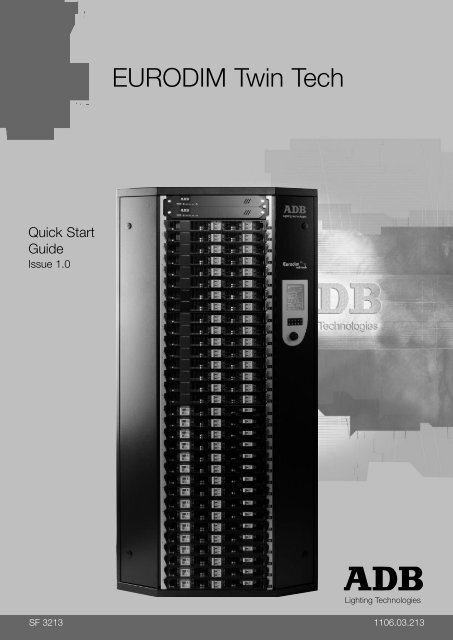
EURODIM Twin Tech<br />
Quick Start<br />
Guide<br />
Issue 1.0<br />
<strong>Lighting</strong> <strong>Technologies</strong><br />
SF 3213 1106.03.213
1. Dimmer Room ........................................................................................................................... 2<br />
1.1 Preparation ........................................................................................................................ 2<br />
1.2 Ventilation of the Dimmer Room ....................................................................................... 2<br />
1.2.1 Example ......................................................................................................................... 2<br />
1.3 Installation of the Cabinets ................................................................................................ 3<br />
1.3.1 Tools for commissioning ................................................................................................ 3<br />
2. Description of the Unit ............................................................................................................. 4<br />
2.1 Contractor's Compartment – Supply ................................................................................. 4<br />
2.1.1 Supply voltage ............................................................................................................... 5<br />
2.1.2 Supply busbar ................................................................................................................ 5<br />
2.1.3 Protected Earth (PE)...................................................................................................... 6<br />
2.1.4 Connecting power supply cables. .................................................................................. 6<br />
2.1.5 Earthing ......................................................................................................................... 6<br />
2.2 Contractor‟s Compartment – Outputs ............................................................................... 7<br />
2.2.1 Outputs to the loads....................................................................................................... 8<br />
2.2.2 DMX and Ethernet terminals ......................................................................................... 8<br />
2.2.3 DMX Connection – type of cable ................................................................................... 8<br />
2.2.4 Pin numbering ................................................................................................................ 9<br />
2.2.5 DIP switches SW1 – termination of the DMX data lines................................................ 9<br />
2.2.6 Local / Remote selector switch CPU1 – CPU2 – Automatic .......................................10<br />
2.3 Power Module Example .................................................................................................. 11<br />
2.4 Central Prosessor Unit (CPU) - Power Supply Unit (PSU)............................................. 11<br />
3. The Human Machine Interface ...............................................................................................12<br />
3.1 Installation of the Human Machine Interface .................................................................. 12<br />
3.2 Description of the Unit ..................................................................................................... 12<br />
3.3 Using the TTD HUMAN INTERFACE (HMI) ................................................................... 13<br />
3.3.1 LCD Display .................................................................................................................13<br />
3.3.2 Numeric Keyboard .......................................................................................................13<br />
3.3.3 Navigation Wheel .........................................................................................................14<br />
3.4 Accessing the TTD HUMAN INTERFACE (HMI)............................................................ 14<br />
4. Screensaver ............................................................................................................................15<br />
5. Online Assistance ...................................................................................................................16<br />
6. Menu Tree-Structure ...............................................................................................................17<br />
7. Cabinet Configuration ............................................................................................................18<br />
7.1 Synchronization............................................................................................................... 18<br />
7.2 Module Control ................................................................................................................ 19<br />
8. Presentation of the Home Page ............................................................................................20<br />
9. Presentation of the Cabinet Diagnostic Page ......................................................................21<br />
9.1 Controller (CTRL) Information ......................................................................................... 21<br />
10. Description of the Menus .......................................................................................................23<br />
11. Patch Menu ..............................................................................................................................25<br />
12. ARTNET Patch Menu ..............................................................................................................27<br />
12.1 Range Key ...................................................................................................................... 28<br />
13. ARTNET Info Menu .................................................................................................................29<br />
13.1 ARTNET Information ....................................................................................................... 29<br />
14. ARTNET Configuration Menu ................................................................................................31<br />
14.1 Selecting Universe Mode ................................................................................................ 31<br />
14.2 Subnet and Universe Port ............................................................................................... 31<br />
www.adblighting.com Quick Start - page 1<br />
Issue 1.0
1. Dimmer Room<br />
1.1 Preparation<br />
- Determine the dimensions of the dimmer room so as to place all EURODIM TWIN<br />
cabinets easily. Provide for an open space of approximately 90 cm in front of the<br />
cabinets to facilitate maintenance. Verify that the room access doors are large<br />
enough to permit passage of the e<strong>qu</strong>ipment. The cabinets can be placed against a<br />
wall or back to back. The supply cables and the load cables can enter the wiring<br />
compartment either from the top or bottom of the cabinet. See drawing for size and<br />
location of cable entries.<br />
- Provide for a free space, minimum 30 cm above the EURODIM TWIN so as to<br />
facilitate the exhaust airflow. The dimensions and weight of the cabinets are<br />
included in the Chapter “Characteristics”.<br />
- Plan for fire extinguishers in compliance with local regulations.<br />
- The lighting of the area should be sufficient for maintenance and inspection. A level<br />
of 300 lux is considered satisfactory.<br />
- Plan for mains outlets in the room, independent of the supply of the dimmers.<br />
- Plan for an Ethernet network to the control room and a cable for remote “CPU1 -<br />
CPU2” selection (if applicable).<br />
1.2 Ventilation of the Dimmer Room<br />
The dimmer room should be dry at all times, free from dust and ventilated in such a<br />
manner as to comply with the following:<br />
- Relative humidity: 5% to 80% without condensation.<br />
- Temperature between + 5 °C and + 35 °C (ideal: + 20 °C).<br />
In order to size the air-conditioning e<strong>qu</strong>ipment re<strong>qu</strong>ired for the dimmer room, refer to the<br />
following dissipations:<br />
- Cabinet electronics including 150 W global value for CPU(s), PSU and fans<br />
- Thyristor modules:<br />
4 x 3 kW modules: 37 W per dimmer (worst case)<br />
3 x 5 kW modules: 69 W per dimmer (worst case)<br />
1 x 10 kW modules: 170 W per dimmer (worst case)<br />
In practice, you may consider an utility factor of 0.6: that is, on the average, 60% of the<br />
dimmers are at full load, while 40% are off.<br />
1.2.1 Example<br />
A dimmer room with a EURODIM TWIN TECH cabinet e<strong>qu</strong>ipped with 128 thyristor<br />
dimmers of 3 kW and a second cabinet with 96 thyristor dimmers of 5 kW. The cabinets<br />
are fitted with a back-up power supply for the processor unit. Utility factor = 0.6<br />
Cabinet N°1<br />
Electronics: 1 x 150 W<br />
Dimmers 128 x 37 W x 0.6 = 2841 W<br />
www.adblighting.com Quick Start - page 2<br />
Issue 1.0
Cabinet N°2<br />
Electronics: 1 x 150 W<br />
Dimmers 96 x 69 W x 0.6 = 3974 W<br />
ROOM TOTAL: 7115 W (1 W = 0.86 kcal/hour) or 6119 kcal/hour.<br />
In this example, it will be necessary to evacuate approximately 7115 W of losses.<br />
1.3 Installation of the Cabinets<br />
1.3.1 Tools for commissioning<br />
Operation<br />
Remove Doors<br />
Remove Card<br />
Cage Dimmers<br />
Open Cables<br />
aperture In &<br />
Out<br />
PE Connection<br />
Power In<br />
Input<br />
Connection<br />
(Bus Bar)<br />
Output<br />
Connection<br />
(Output)<br />
PE connection<br />
(Output)<br />
Connection<br />
Designation<br />
Pan Head Screw<br />
M4x12 PZ<br />
Pan Head Screw<br />
M4x12 PZ<br />
Slotted Flat Head<br />
Screw M4x12 PZ<br />
Pan Head Screw<br />
M4x12 PZ<br />
Qty Tor<strong>qu</strong>e Tools<br />
1 1.5 Nm Screw Driver PZ2<br />
5 2 Nm Screw Driver PZ2<br />
16 1.5 Nm Screw Driver PZ 2<br />
8 2 Nm Screw Driver PZ 2<br />
Nut M10 1 8 to 10 Nm Metric Wrenches 17<br />
Nut M12 4 8 to 10 Nm<br />
Bolt M12 4 8 to 10 Nm<br />
Terminal<br />
Connection<br />
Free Drive Screw<br />
2 x Metric Wrenches 19<br />
256 1.5 Nm Flat Screw Driver 1 x 6.5<br />
Screws M4x8 128 1.5 Nm Screw driver PZ 1<br />
DMX<br />
Connection<br />
Ethernet<br />
Connection<br />
RJ 45 1<br />
Phoenix MSTBVA<br />
2.5 – 6<br />
6 0.5 Nm Flat Screw Driver 0.5 x 3.5<br />
RJ 45 1<br />
www.adblighting.com Quick Start - page 3<br />
Issue 1.0
2. Description of the Unit<br />
2.1 Contractor's Compartment – Supply<br />
Front access only is re<strong>qu</strong>ired. Cable entry is possible through bottom and top of the<br />
cabinet. Cover panels for the unused cable entry/ exit apertures are supplied.<br />
In order to gain maximum space to access<br />
the cabinet for installation and maintenance<br />
purposes, remove the two doors, loosen the<br />
16 crosshead screws in the back and 3 left +<br />
right at the bottom and dismount the entire<br />
card cage in one piece.<br />
Mounting the cabinet, first insert the card<br />
cage, enter two power modules to align<br />
the rack and fasten the 16 screws. Put the<br />
doors in place and reconnect the doors<br />
earth connection.<br />
www.adblighting.com Quick Start - page 4<br />
Issue 1.0
2.1.1 Supply voltage<br />
The high voltage/low voltage power transformer MUST ABSOLUTELY provide a three<br />
phase star system with available neutral (3NPE-400), and rated line voltage 380 V to<br />
415 V between phases and 220 V to 240 V rated voltage between each phase and<br />
neutral. See “Protections” for more details.<br />
The supply cable must have the four current-carrying power conductors (not necessarily<br />
the PE conductor) twisted under the same sleeve, in order to reduce the noise induced by<br />
large dimmed currents.<br />
The neutral conductor must be of e<strong>qu</strong>al or larger size than the phase conductors.<br />
See the Appendix to this manual for more details about power supply systems for dimmer<br />
systems.<br />
2.1.2 Supply busbar<br />
The three phase connection points are labeled L1 (phase No. 1, phase R), L2 (phase No.<br />
2, phase S) and L3 (phase No. 3, phase T).<br />
The Neutral is labeled N and the colour code for the Neutral is blue, as per IEC<br />
Recommendation 446.<br />
The Phase and Neutral connection bars have 4 holes of Ø 13 mm, with 22 mm distance<br />
between centers. Connections are suitable for size M 12 bolts and nuts, for connection of<br />
up to four supply conductors. The conductors must be fitted with cable lugs.<br />
www.adblighting.com Quick Start - page 5<br />
Issue 1.0
2.1.3 Protected Earth (PE)<br />
The Protective Earth (PE) on<br />
the busbar connection is a bolt<br />
and nut, size M10. Colour<br />
code: green/yellow. The<br />
e<strong>qu</strong>ipotential connection,<br />
connecting the metal frame, is<br />
provided at the top of the<br />
supply cabling compartment.<br />
This connection is already<br />
wired to the busbar PE. An<br />
additional PE connection is<br />
provided on the cabinet‟s<br />
bottom of the supply<br />
compartment. All necessary<br />
nuts and washers are included.<br />
2.1.4 Connecting power supply cables.<br />
Supply cables can be wired in<br />
parallel, while of these cables<br />
must contain the three phases<br />
and the Neutral under the same<br />
sleeve. This cable must be<br />
protected in the switchboard.<br />
The total size of the conductors<br />
must be chosen depending on<br />
the total power of the dimmers,<br />
the utility factor, the general<br />
protection on the supply side,<br />
the voltage drop in the line and<br />
local regulations. We suggest<br />
the use of several cables placed<br />
in parallel, to facilitate the work<br />
of the contractor: the cables<br />
usually have a bending radius<br />
of min. 15 times their external<br />
diameter. Respect an angle of<br />
30 degree to connect the supply<br />
cable in order to achieve<br />
necessary distance between the<br />
cables and busbar. Use the<br />
wholes on bottom and top to connect the cable wraps for stress relief.<br />
2.1.5 Earthing<br />
The sound or video earth should be separated from the dimmer earth. The distance<br />
between the dimmer earth and the others should be as large as possible. Refer to local<br />
regulations for earthing.<br />
www.adblighting.com Quick Start - page 6<br />
Issue 1.0
2.2 Contractor’s Compartment – Outputs<br />
Front access only is re<strong>qu</strong>ired. Cable entry is possible through bottom and top of the<br />
cabinet.<br />
BACK:<br />
ODD NUMBERED<br />
MODULES<br />
1.1 – 1.4 (L1)<br />
FRONT:<br />
EVEN NUMBERED<br />
MODULES<br />
2.1 - 2.4 (L2)<br />
MODULE 15 (L3)<br />
LINE<br />
NEUTRAL 15.1<br />
LINE<br />
NEUTRAL 15.2<br />
LINE<br />
NEUTRAL 15.3<br />
LINE<br />
NEUTRAL 15.4<br />
4 x PE<br />
Detail A<br />
A<br />
www.adblighting.com Quick Start - page 7<br />
Issue 1.0
2.2.1 Outputs to the loads<br />
The cabling compartment with output terminals is on the right hand side. The load<br />
terminals are mounted next to the relevant module. The numbering is shown on selfadhesive<br />
labels.<br />
These terminal blocks are suitable for cable sizes up to 10 mm². Adaptors are available<br />
for cables up to 25 mm². Grey = L; blue = N.<br />
The load cables must be sized in accordance with local regulations. Increased sizes may<br />
be re<strong>qu</strong>ired in order to reduce the voltage drop on the line to the luminaire. We suggest<br />
limiting the voltage drop to 3%.<br />
The data cables may follow the power cables on the condition that they are minimum<br />
250 mm apart or in a separate shielded trunking (e.g. steel tube). Sound and video cables<br />
must be kept at a minimum distance of 500 mm from all power cables. If cables or ducts<br />
have to cross, then a crossing at right angles will reduce interferences.<br />
2.2.2 DMX and Ethernet terminals<br />
All control signals are connected to the data input board PCB3031, located at the top of<br />
the right-hand cabling compartment.<br />
PCB 3031<br />
2.2.3 DMX Connection – type of cable<br />
Use data cable with two twisted pairs + 1 conductor (can be from a third pair) + overall<br />
screen. Use data cable which is suitable for digital data transmission (EIA 485 / RS 485;<br />
250 kBaud). The data cable must meet the DMX512-A specification (ANSI E1.11 – 200x).<br />
Do not use audio cable for DMX, as this has the wrong capacitance and impedance and<br />
WILL NOT reliably transmit DMX signals. The DMX signal uses fairly high fre<strong>qu</strong>encies,<br />
well above 1000 kHz.<br />
Cable model LIYCY 3 x 2 x 0.35 + shield is suitable for this purpose. Two pairs are used<br />
for data transmission, and one conductor for the 0V (common) GND. The cable shield is<br />
connected to the PE.<br />
Use of Ethernet cables for DMX<br />
It is allowed to use Cat5 (or higher) STP and FTP Ethernet cable for<br />
DMX.<br />
STP = shielded twisted pair.<br />
FTP = foil twisted pair.<br />
UTP = unshielded twisted pair.<br />
WARNING: UTP Ethernet cable is not suitable for DMX.<br />
www.adblighting.com Quick Start - page 8<br />
Issue 1.0
Each EURODIM TWIN TECH processor is e<strong>qu</strong>ipped with two physical DMX inputs, and<br />
one Ethernet port. For cabinets with optional „instant back-up‟, each processor has its own<br />
independent data connectors.<br />
2.2.4 Pin numbering<br />
For standard DMX cables (2 pairs + screen), the connectors X1 through X8 are connected<br />
as follows:<br />
1 screen, and 0 V<br />
2 data 1- (DMX)<br />
3 data 1+ (DMX)<br />
4 data 2- (second data pair)<br />
5 data 2+ (second data pair)<br />
Note: this numbering is different from the XLR5.<br />
For optimum EMC (Electro-Magnetic Compatibility) performance however, we recommend<br />
to separate 0V from PE. The wiring should be as follows:<br />
1 0 Volt conductor (different from the screen)<br />
2 data 1- (DMX)<br />
3 data 1+ (DMX)<br />
4 data 2- (second data pair)<br />
5 data 2+ (second data pair)<br />
6 screen in the DMX cable and connection to PE.<br />
All screens in all cables should be interconnected. One end only should be connected to<br />
PE, to prevent an earth loop.<br />
Pin configuration of the RJ45-for-DMX:<br />
- pin 2 = data 1- (DMX)<br />
- pin 1 = data 1+ (DMX)<br />
- pin 6 = data 2-<br />
- pin 3 = data 2+<br />
- pin 7 and 8 = common 0V<br />
2.2.5 DIP switches SW1 – termination of the DMX data lines<br />
On PCB3031, SW1 switches 1 through 4 allow termination of the cabinets four DMX<br />
inputs.<br />
To terminate CPU1-DMXA: set Switch 4 to ON.<br />
To terminate CPU1-DMXB: set Switch 3 to ON.<br />
To terminate CPU2-DMXA: set Switch 2 to ON.<br />
To terminate CPU2-DMXB: set Switch 1 to ON.<br />
DIP switches instead of link cables<br />
On PCB3031, SW1 switches 5 and 6 connect “DMX1A Through” with “DMX2A In”.<br />
Similarly, SW1 switches 7 and 8 connect “DMX1B Through” with “DMX2B In”.<br />
This is a convenient and reliable alternative for short jumper cables.<br />
www.adblighting.com Quick Start - page 9<br />
Issue 1.0
Enable_CPU1<br />
Enable_CPU2<br />
2.2.6 Local / Remote selector switch CPU1 – CPU2 – Automatic<br />
The CPU selector switch is located next to<br />
the CPU slots. The connection for the<br />
remote selector switch is provided in the<br />
right compartment on the PCB 3031. Please<br />
see the attached drawing for the exact wiring<br />
of the switch.<br />
The following table explains the use of the<br />
local and remote switch.<br />
Jumpers J1 Local switch Remote Switch Terminal signals (*) CPU Active<br />
(PCB3031)<br />
Not<br />
mounted CPU1 N/A 1 0 CPU1 (**)<br />
CPU2 N/A 0 1 CPU2 (**)<br />
A-R CPU1 1 0 CPU1 (**)<br />
A-R CPU2 0 1 CPU2 (**)<br />
Automatic or<br />
A-R not connected 1 1 Automatic<br />
Wires short circuited<br />
software<br />
(***) 0 0<br />
selection<br />
Mounted N/A N/A 0 (****) 0 (****)<br />
The jumper J1 is by default NOT mounted.<br />
- Power supply voltage: Vcc = 24V (thru 1.5K and protection fuses on PCB3031)<br />
- Enable_CPU signals are active high<br />
- (*) 0 = terminal connected to 0 V; 1 = terminal is open<br />
- (**) Manual selection by the user<br />
- (***) Only for information<br />
- (****) Value forced by presence of Jumpers J1<br />
For remote CPU selection, use a shielded cable of 3 x 0.5 mm². The shield should at one<br />
end be connected to PE. See wiring and interconnection diagram in 30-490 and 30-500.<br />
www.adblighting.com Quick Start - page 10<br />
Issue 1.0
2.3 Power Module Example<br />
OUTPUT CONNECTOR<br />
DATA CONNECTION<br />
INPUT CONNECTOR<br />
MODULE LABEL<br />
SUPPLY VOLTAGE<br />
MCB per CIRUIT<br />
RCD per MODULE (optional)<br />
OUTPUT CURRENT PER CIRCUIT<br />
OUTPUT VOLTAGE PER CIRCUIT<br />
2.4 Central Prosessor Unit (CPU) - Power Supply Unit (PSU)<br />
Ordering EURODIM TWIN TECH you have the choice to either configure the cabinet with<br />
2 identical CPU units for full data and power backup or 1 CPU unit + 1 PSU unit for power<br />
supply backup.<br />
In order to assure permanent contact with the CPU backplane the units shall be secured<br />
with one screw left and right. (See below)<br />
DMX A+B IN TRAFFIC<br />
ETHERNET TRAFFIC<br />
LINE 1 LINE 3<br />
LINE 2<br />
FAILURE INDICATOR<br />
PROCESSOR LED<br />
24 V SUPPLY INDICATOR<br />
www.adblighting.com Quick Start - page 11<br />
Issue 1.0
3. The Human Machine Interface<br />
3.1 Installation of the Human Machine Interface<br />
The EDTT may be delivered without the TTD Human Interface installed. In some areas<br />
this unit is optional. If the TTD Human Interface is not present, then the dimmer shall be<br />
controlled by the TTD Management Software.<br />
The TTD Human Interface is found in a separate packing. In case such a unit has to be<br />
reordered the <strong>ADB</strong> code Nr is: 1115.10.055. The package includes the TTD HUMAN<br />
INTERFACE with a mounted metal back part, one connection cable, one SD card<br />
(mounted in HUMAN INTERFACE) and one EURODIM Twin Tech user and programming<br />
manual in English and French.<br />
Installation Procedure:<br />
1. Open the door of the right compartment.<br />
2. Remove the protective cover covering the opening in the door panel.<br />
3. Take the metal lid off the back of the Human Interface.<br />
4. Prepare the flat cable (included in package) – It has on one side a large<br />
connector and on the other two smaller connectors.<br />
5. Plug the flat cable (large connector) into the socket on the upper right hand<br />
corner (viewed from the PCB side) with the red cable facing towards the right.<br />
Do not force the multi pin connector into the socket!<br />
6. Fit the Human Interface with its metal cover from the backside on the door and<br />
screw the nut tight with a 7 mm wrench.<br />
7. Connect the 2 flat cable connectors to the CPU communication panel<br />
connectors CPU0 and CPU1 (see drawing). The Connector with the red cable<br />
facing out shall be connected to the connector CPU1<br />
3.2 Description of the Unit<br />
The user is provided with:<br />
1 - A backlit LCD touch-screen enabling access to all menus.<br />
2 - A numeric keyboard.<br />
3 - A navigation/validation pushbutton – wheel.<br />
www.adblighting.com Quick Start - page 12<br />
Issue 1.0
When the right-hand side door of the cabinet is opened, the rear of the Unit gives access<br />
to the following:<br />
1 - An opening on the rear face to activate the software reset button (in the event<br />
that the touch screen becomes blocked)<br />
2 - An opening in the side face for insertion of the SD memory card<br />
3 - A connector to link up to the Twin Tech cabinet Controller units.<br />
4 - A contrast potentiometer and a brightness potentiometer for the LCD touchscreen<br />
3.3 Using the TTD HUMAN INTERFACE (HMI)<br />
3.3.1 LCD Display<br />
When the cabinet is activated, an initial home page appears on the LCD display, allowing<br />
access to the “Cabinet diagnostic” screen page, which is considered as the main screen.<br />
Manually pressing the touch-zones on the main screen or the screens of the different<br />
menus generally enables the user to:<br />
Edit a field to be filled in,<br />
Validate the said field,<br />
Increment or decrement a value,<br />
Validate or cancel a function,<br />
Display one of the different available menus,<br />
Return to the main screen or the list of menus.<br />
The key or zone selected is highlighted.<br />
There is no recording confirmation when the screen page is changed.<br />
When a field is edited and its value is modified, it is possible to cancel its recording before<br />
validation by pressing another touch-zone on the screen.<br />
3.3.2 Numeric Keyboard<br />
The numeric keyboard enables the user to:<br />
- Add a field‟s value when the field is edited,<br />
- Increment a field‟s value (by pressing key 1) or decrement (by pressing key 0),<br />
www.adblighting.com Quick Start - page 13<br />
Issue 1.0
- Directly access a screen page: next page using key 1; previous page using key 0;<br />
- Enter the access code in order to access the different user levels.<br />
Note: any value entered that is beyond the user range is limited to the maximum value.<br />
3.3.3 Navigation Wheel<br />
The wheel may be handled by rotating clockwise or anti-clockwise in order to:<br />
Select a field from a menu or choose a menu from the two menu screen pages,<br />
Cancel the validation of a field when the latter is edited.<br />
Pressing the navigation wheel enables the user to:<br />
Edit a field to be filled in,<br />
Validate the highlighted field,<br />
Validate or cancel a function,<br />
Select a menu or function.<br />
3.4 Accessing the TTD HUMAN INTERFACE (HMI)<br />
There are several possible user access levels. The first two screens (home and main<br />
screen) are accessible to all users.<br />
An access code needs to be entered in order to access the “Menu” screen. Depending on<br />
the authorised access level, the user will be able to make modifications or launch<br />
functions.<br />
The table below indicates the functions accessible to the user according to the access<br />
level:<br />
Function/menu Level 0<br />
Code 5555<br />
Level 1<br />
Code 6666<br />
Level 2<br />
Code 7777<br />
Level 3<br />
Code 8888<br />
View the parameters No Yes Yes Yes<br />
Edit the patch No No Yes Yes<br />
Test a dimmer No No Yes Yes<br />
Alter the settings No No Yes Yes<br />
Scan the loads No No No Yes<br />
Edit the laws and No No No Yes<br />
multiplying factor<br />
Edit the ARTNET No No Yes Yes<br />
parameters<br />
Manage the Cues No No Yes Yes<br />
Load/Save the No No No Yes<br />
parameters<br />
Manually<br />
No No No Yes<br />
synchronise<br />
between controllers<br />
<strong>ADB</strong> service No No No No<br />
Level 0 does not allow access to any menu or function.<br />
Depending on the authorised access level, certain functions or menus remain blocked.<br />
Should you attempt to access these, the software will ask you to enter the access code for<br />
the next level in order to authorise access to the function or menu.<br />
The access-level indication can be viewed on all the screen pages. It is located in the top<br />
right-hand corner and is signalled by a figure representing the current access level (from 0<br />
to 3), followed by a key symbol.<br />
www.adblighting.com Quick Start - page 14<br />
Issue 1.0
4. Screensaver<br />
If whilst accessing a screen page other than the home page, the user does not handle the<br />
touch-screen, keyboard or wheel for a period of more than one minute, the software<br />
returns to the home page. The access code will become 0. To access the "Menu" screen<br />
pages, an access code will again need to be entered.<br />
www.adblighting.com Quick Start - page 15<br />
Issue 1.0
5. Online Assistance<br />
A "HELP" key is provided in the bottom right-hand corner of all of the screen pages,<br />
allowing touch-access to a help function, relating to the page consulted.<br />
Press the “BACK” touch-button to return to the screen page.<br />
www.adblighting.com Quick Start - page 16<br />
Issue 1.0
6. Menu Tree-Structure<br />
www.adblighting.com Quick Start - page 17<br />
Issue 1.0
7. Cabinet Configuration<br />
The upper part of the Twin Tech cabinet may be e<strong>qu</strong>ipped with:<br />
- Two Controller units,<br />
- or a Controller unit and a backup power supply module.<br />
The Controller units, control all of the circuits (128 max.) constituting the modules<br />
available in the cabinet (32 max.), according to the configuration recorded by the Unit<br />
software (patch) and the channel values present on the DMX A, DMX B and ARTNET<br />
inputs (ETHERNET connection).<br />
1<br />
7.1 Synchronization<br />
The human interface is synchronized continuously between two controllers (if present).<br />
If two controllers are present, data from a controller (the one inserted into the slot from the<br />
top), with the exception of the page "Diagnosis of the cabinet" or information from the<br />
selected controller using the tabs "CTRL1" and "CTRL2".<br />
If the controller 1 is a not functional, timing continues with the controller 2.<br />
If the cabinet has only one controller all the information obtained from this controller<br />
Note: Only the controller in slot from the top is able to detect modules in the cabinet (see<br />
Chapter Power Configuration) and to report the status of sinewave and thyristor<br />
modules with full diagnostic option (see section "Module Measuring" and<br />
"Diagnostic Modules").<br />
If one controller is functional and inserted into the slot at the bottom, the cabinet<br />
will work but the human interface will not be able to present the modules or<br />
diagnostic information modules<br />
www.adblighting.com Quick Start - page 18<br />
Issue 1.0
7.2 Module Control<br />
The selector allows the Controller unit in service to be chosen. It may be set to position 1,<br />
A/R or 2.<br />
When a controller is selected (1 or 2), the DMX A, DMX B and ARTNET signals present at<br />
this controller‟s input are used.<br />
The software configuration is HTP (Highest Take Precedence) by default. It is the highest<br />
value of the DMX A, DMX B and ARTNET inputs (three available universes) and cue<br />
played and allocated to a circuit that is taken into account in order to give the output<br />
dimming level.<br />
When the selector is set to A/R, the circuits of each module are controlled according to the<br />
following rule: the highest value amongst the DMX A, DMX B and ARTNET inputs of the<br />
two controllers is taken into account when controlling this circuit.<br />
Example: Control using DMX A and DMX B inputs<br />
Notes: The PCB3031 board also enables:<br />
the DMX A inputs to be connected between controllers (SW1, selectors 5 and 6<br />
set to ON)<br />
the DMX B inputs to be connected between controllers (SW1, selectors 7 and 8<br />
set to ON)<br />
www.adblighting.com Quick Start - page 19<br />
Issue 1.0
8. Presentation of the Home Page<br />
This screen page is displayed as soon as the cabinet is switched on. It gives the<br />
information concerning the start address for the DMX A and B inputs and the three<br />
ARTNET universes.<br />
Information available for start address (valid for DMX and ARTNET):<br />
"x": channel value to address cabinet output 1, 1 < x < 512<br />
"not used": channel value = 0 or > 512<br />
"- - - - -": no circuit physically present in cabinet location 1, or circuit identification<br />
error in cabinet location 1 or operating fault<br />
To access the diagnostic page, press the arrow.<br />
www.adblighting.com Quick Start - page 20<br />
Issue 1.0
9. Presentation of the Cabinet Diagnostic Page<br />
This screen shows the cabinet diagnostic information.<br />
This page is divided into three zones:<br />
A zone (CTRL1 or CRTL2 tab) providing information on the controllers,<br />
A zone (EURODIM TT INFO) providing general information on the cabinet‟s<br />
operation, identification of the modules by the controller and signalling the alarms,<br />
A zone (INFO DMX) providing information on the DMX inputs and the functions<br />
associated with these inputs.<br />
Two keys enable the user to:<br />
Access the two menu screen pages; MENU key. To access the Menu, when<br />
prompted by a specific window the user access code needs to be entered using<br />
the keyboard, without validating.<br />
Access the ARTNET information; ENET key. This page is accessible regardless of<br />
the user access level.<br />
9.1 Controller (CTRL) Information<br />
Note: The information is present if the controller is physically connected and operational<br />
in the cabinet.<br />
- CTRL board active:<br />
• "Yes" if the controller is selected by the cabinet controller selector (position<br />
1 for controller 1 and position 2 for controller 2 or A/R for both),<br />
• "No" if the controller is not selected (circuits not controlled by this<br />
controller).<br />
- Fre<strong>qu</strong>ency: displays the network fre<strong>qu</strong>ency measured at the controller‟s input<br />
www.adblighting.com Quick Start - page 21<br />
Issue 1.0
- Hardware/communication:<br />
• "OK" if the controller is operating correctly,<br />
• "Not OK" if a problem is detected. In this case, an error message and an<br />
exclamation mark appear in the EURODIM TT INFO zone.<br />
- Software version: software version present in the controller<br />
- Temperature:<br />
• "OK" if the temperature measured in the controller is acceptable,<br />
• "Not OK" if the temperature measured in the controller is too much high. In<br />
this case, the control value of all of the active circuits is reduced by 1%<br />
every minute until the temperature measured becomes again acceptable*<br />
(also see paragraph on the operation of the ventilation within the<br />
cabinet).Looks can be recorded in variety of methods, but a pop-up window<br />
gives you options about what is to be recorded.<br />
www.adblighting.com Quick Start - page 22<br />
Issue 1.0
10. Description of the Menus<br />
Two screen pages are available in order to choose a function, enabling the cabinet to be<br />
configured using one of the following menus:<br />
<br />
<br />
<br />
<br />
<br />
<br />
<br />
<br />
<br />
<br />
<br />
<br />
<br />
<br />
<br />
<br />
Patch: to edit patch A or B for each circuit<br />
Laws/Mult.F: to choose the law used and the multiplying factor for each of the<br />
circuits<br />
Conf. Power: to assign the modules used and detected in the 32 cabinet locations<br />
Cues/DMX fail: cue management and action to be performed after a absence of<br />
DMX/ARTNET<br />
View all: overall view of all the parameters per module or per circuit<br />
Test/Flash: to launch a test or the flash of a circuit<br />
Load/Save: to save and load the parameters of the controllers and of each circuit<br />
Settings: Human-Machine interface configuration<br />
Scan loads: to measure/scan the loads connected at the outputs of each circuit<br />
Mod. Meas.: gives the voltage and current measurements for each circuit<br />
Mod. Diag.: gives the diagnosis of the outputs of each module<br />
ARTNET patch: to edit the patch of the three ARTNET universes for each circuit<br />
View ARTNET: general information on the ARTNET universes and the Ethernet<br />
connection<br />
ARTNET set.: to configure the three ARTNET universes<br />
<strong>ADB</strong> Service: function available to <strong>ADB</strong> <strong>tech</strong>nical service only<br />
Synchro: to synchronise the parameters recorded between each of the controllers<br />
www.adblighting.com Quick Start - page 23<br />
Issue 1.0
Note:<br />
All the information displayed in the different menus originates from controller 1 if<br />
two controllers are present in the cabinet.<br />
If only controller 2 is present, all the information displayed in the different menus<br />
will originate from the latter. When changing the patch, power multiplication<br />
factor, law... the new data is sent to each controller. The cirsuits defined as<br />
« empty slot » or « undefined slot » are not editable and not visible in any<br />
screens. It appears again when the circuit will not be declared as “empty slot” or<br />
“undefined slot”.<br />
www.adblighting.com Quick Start - page 24<br />
Issue 1.0
11. Patch Menu<br />
This function is used to configure a patch on a circuit or set of circuits for the DMX A and<br />
DMX B signal.<br />
This configuration enables the user to attribute the value of a DMX A and DMX B signal<br />
channel to the control of one of the cabinet‟s circuits.<br />
Module<br />
reference<br />
DMX<br />
channel<br />
Reminder<br />
The referencing of the modules in the cabinet starts at 1 in relation to the first location<br />
located at the top of the cabinet, up to 32.<br />
The left-hand column contains the referencing of the modules and circuits present in the<br />
cabinet.<br />
The figure in the right-hand column is the channel attributed in the DMX signal.<br />
Select patch A or B to start with<br />
Use the wheel to rapidly move between all the rows of the patch. The row selected is<br />
highlighted.<br />
To attribute a channel, position on a row and use:<br />
<br />
<br />
<br />
<br />
The touch-screen and the numeric keyboard to enter a value,<br />
Press key 1 directly to increment the value by 1 (between 1 and 512) in relation to<br />
the first value available on a previous row,<br />
Press key 0 directly to decrement the value by 1 (between 1 and 512) in relation to<br />
the first value available on a previous row,<br />
The Range key in order to enter values between two circuit references.<br />
www.adblighting.com Quick Start - page 25<br />
Issue 1.0
Important: Specific case for row 1/1: if key 0 or 1 is used, the value taken into<br />
consideration corresponds to the content of output 128 if available, otherwise<br />
output 127, and so on.<br />
If the value entered is 0 or greater than 512, the circuit is not controllable and<br />
the message "Not used" is displayed.<br />
www.adblighting.com Quick Start - page 26<br />
Issue 1.0
12. ARTNET Patch Menu<br />
This function is used to configure a patch on a circuit or a set of circuits for each of<br />
universes 1, 2 and 3.<br />
This configuration is used to attribute the value of a channel of each universe to the<br />
control of a circuit of the cabinet.<br />
Reminder<br />
The referencing of the modules in the cabinet starts at 1 in relation to the first location<br />
situated at the top of the cabinet, up to 32.<br />
The left-hand column contains the referencing of the modules and circuits present in the<br />
cabinet:<br />
Example: Value 1/1: references module 1/circuit 1 of the module<br />
The right-hand figure indicates the output on the cabinet (from 1 to 128).<br />
The channel attributed for each universe is given in the right-hand column.<br />
www.adblighting.com Quick Start - page 27<br />
Issue 1.0
Start by selecting universe 1, 2 or 3.<br />
Use the wheel to rapidly move between all the rows of the patch. The row selected is<br />
highlighted.<br />
To attribute a channel, position on a row and use:<br />
The touch-screen and the numeric keyboard to enter a value,<br />
Press key 1 directly to increment the value by 1 (between 1 and 512) in relation to<br />
the first value available on a previous row,<br />
Press key 0 directly to decrement the value by 1 (between 1 and 512) in relation to<br />
the first value available on a previous row,<br />
The Range key in order to enter values between two circuit references.<br />
Important: Specific case for row 1/1: If key 0 or 1 is used, the value taken into<br />
consideration corresponds to the content of output 128 if available, otherwise<br />
to output 127, and so on.<br />
If the value entered is 0 or greater than 512, the circuit cannot be<br />
coordinated and the message “Not used” is displayed.<br />
12.1 Range Key<br />
Used to attribute an ascending patch value in graduations of 1 to a set of circuits, included<br />
within a range.<br />
Enter:<br />
The start dimmer number (From dim),<br />
The end dimmer number (To dim),<br />
The start channel value to be taken into consideration for the increment in steps of 1<br />
Confirm with the OK button.<br />
Note: the circuit's first number ("From dim") must be < the circuit‟s second number ("To<br />
dim") during definition of the range. Otherwise, the range between two circuits<br />
cannot be validated.<br />
The ALL key is used in order to directly enter the 128 circuits of the cabinet.<br />
www.adblighting.com Quick Start - page 28<br />
Issue 1.0
13. ARTNET Info Menu<br />
These two screens show the status of the ARTNET connections, the configuration<br />
information for the three universes managed by each controller, as well as the IP<br />
addresses entered at each controller.<br />
To Dock a window:<br />
This page is divided into two zones:<br />
A zone (CTRL1 or CRTL2 key) providing information on the status of the universes<br />
and their configurations for each controller,<br />
A zone (ENET) providing the IP addresses entered for each controller.<br />
Note: Only the "ARTNET present/missing" information depends on the controller.<br />
In effect, each controller has its own ARTNET input. The back button, called<br />
"MENU" or "DIAG" is used to return to the previous screen.<br />
13.1 ARTNET Information<br />
For each of the three universes (1, 2, 3), the following information is available:<br />
- Present:<br />
• "Yes": detection of the Ethernet frame corresponding to the universe,<br />
• "No": no reception of the Ethernet frame corresponding to the universe.<br />
- Used: see "ARTNET Configuration" menu<br />
• "yes": the universe values are taken into consideration for the control of the<br />
circuits<br />
• "no": the universe values are not taken into consideration for the control of the<br />
circuits<br />
www.adblighting.com Quick Start - page 29<br />
Issue 1.0
- Fail: action implemented in the absence of the universe (see “Priority/DMX fail”<br />
menu), three actions are possible:<br />
• "last value": the last values received to control the circuits are used<br />
permanently as long as the universe is missing,<br />
• "cue" 0: the values of the universe channels are replaced by the content of cue<br />
0 and will be played as long as the universe is missing,<br />
• "black": the control value of each circuit fades to zero intensity (black) in 5<br />
seconds.<br />
• When the universe is present once more, a fade is launched to the intensities<br />
given by ARTNET in a time of 5 seconds.<br />
When the universe is present once more, a fade is launched to the intensities given by<br />
ARTNET in a time of 5 seconds.<br />
- start addr.: value of the universe channel to address cabinet output 1, see "ARTNET<br />
PATCH" menu<br />
• "x": 1 ≤ x ≤ 512<br />
• "not used": channel value = 0 or > 512<br />
• "- - - - -": no circuit physically present in cabinet location 1, or circuit<br />
identification error in cabinet location 1 or operating fault.<br />
- Patch: see "ARTNET PATCH" menu,<br />
• Yes: the addressing entered in each patch at the circuits is not in ascending<br />
order,<br />
• No: the addressing entered in each patch at the circuits is in ascending order,<br />
e.g. 1, 2, 3, 4,…., 128 in the case where 32 modules are present in the<br />
cabinet.<br />
- Subnet: value between 0 and 15, see "ARTNET config" menu<br />
- Port: value between 0 and 15, see "ARTNET config" menu<br />
Note: When the ARTNET entries are controlled by an ISIS rotating <strong>ADB</strong> console, all the<br />
subnets must have the same number.<br />
Ethernet Information<br />
The IP address of each controller and the value of the sub-network mask are given.<br />
Important: the IP addresses of each controller must be different. If this is not the case, it<br />
is imperative to address the <strong>ADB</strong> <strong>tech</strong>nical department.<br />
www.adblighting.com Quick Start - page 30<br />
Issue 1.0
14. ARTNET Configuration Menu<br />
This function configures the ARTNET universes for the two controllers as well as the<br />
subnet and port values.<br />
14.1 Selecting Universe Mode<br />
For each universe, choose the operating mode:<br />
- “Not Used” mode: the universe is not taken into consideration for the control of the<br />
circuits,<br />
- “ARTNET” mode: the universe is taken into consideration for the control of the<br />
circuits.<br />
Touch to select the mode. The mode selected must be highlighted.<br />
14.2 Subnet and Universe Port<br />
For each universe, fill-in the subnet and the port such that it is identical to the<br />
configuration of the control console.<br />
Subnet and port value: between 0 and 15.<br />
Position on the subnet value (port), either by touching the screen or using the wheel. The<br />
value is highlighted.<br />
- Type the value using the keyboard,<br />
- Validate the value by touching the screen to select the zone in <strong>qu</strong>estion, or using<br />
the wheel.<br />
www.adblighting.com Quick Start - page 31<br />
Issue 1.0
Personal Notes<br />
www.adblighting.com Quick Start - page 32<br />
Issue 1.0
<strong>ADB</strong> - Your Partner for Light<br />
Belgium N.V. <strong>ADB</strong>-TTV <strong>Technologies</strong> S.A.<br />
(Group Head<strong>qu</strong>arters) Leuvensesteenweg 585, B-1930 Zaventem<br />
Tel : +32.2.709.32.11, Fax : +32.2.709.32.80, E-Mail : adb@adblighting.com<br />
France <strong>ADB</strong> S.A.S. Sales Office: 92, Avenue Jean Jaurès F-92120 Montrouge<br />
Tel : +33.1.41.17.48.50, Fax : +33.1.42.53.54.76, E-Mail : adb.fr@adblighting.com<br />
Factory & Group Logistics Centre: Zone industrielle Rouvroy F-02100 Saint-Quentin<br />
Tel : +33.3.23.06.35.70, Fax : +33.3.23.67.66.56, E-Mail : adb.fr@adblighting.com<br />
Hong Kong <strong>ADB</strong> <strong>Lighting</strong> Asia Ltd<br />
Suite 2414, Level 24, Two Pacific Place, 88 Queensway<br />
Tel : +852 903 232 27, E-mail : adb@adblighting.com<br />
www.adblighting.com<br />
<strong>Lighting</strong> <strong>Technologies</strong><br />
Subject to modifications<br />
M-3213-E-09p


