
You also want an ePaper? Increase the reach of your titles
YUMPU automatically turns print PDFs into web optimized ePapers that Google loves.
GC COLUMNS | CAPILLARY COLUMNS<br />
Column Installation<br />
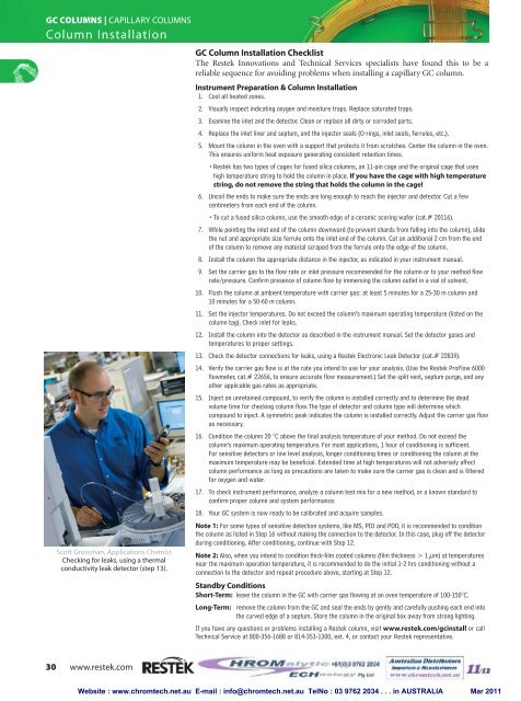
Scott Grossman, Applications Chemist<br />
Checking for leaks, using a thermal<br />
conductivity leak detector (step 13).<br />
GC Column Installation Checklist<br />
The Restek Innovations and Technical Services specialists have found this to be a<br />
reliable sequence for avoiding problems when installing a capillary GC column.<br />
Instrument Preparation & Column Installation<br />
1. Cool all heated zones.<br />
2. Visually inspect indicating oxygen and moisture traps. Replace saturated traps.<br />
3. Examine the inlet and the detector. Clean or replace all dirty or corroded parts.<br />
4. Replace the inlet liner and septum, and the injector seals (O-rings, inlet seals, ferrules, etc.).<br />
5. Mount the column in the oven with a support that protects it from scratches. Center the column in the oven.<br />
This ensures uniform heat exposure generating consistent retention times.<br />
•Restek has two types of cages for fused silica <strong>columns</strong>, an 11-pin cage and the original cage that uses<br />
high temperature string to hold the column in place. If you have the cage with high temperature<br />
string, do not remove the string that holds the column in the cage!<br />
6. Uncoil the ends to make sure the ends are long enough to reach the injector and detector. Cut a few<br />
centimeters from each end of the column.<br />
•To cut a fused silica column, use the smooth edge of a ceramic scoring wafer (cat.# 20116).<br />
7. While pointing the inlet end of the column downward (to prevent shards from falling into the column), slide<br />
the nut and appropriate size ferrule onto the inlet end of the column. Cut an additional 2 cm from the end<br />
of the column to remove any material scraped from the ferrule onto the edge of the column.<br />
8. Install the column the appropriate distance in the injector, as indicated in your instrument manual.<br />
9. Set the carrier gas to the flow rate or inlet pressure recommended for the column or to your method flow<br />
rate/pressure. Confirm presence of column flow by immersing the column outlet in a vial of solvent.<br />
10. Flush the column at ambient temperature with carrier gas: at least 5 minutes for a 25-30 m column and<br />
10 minutes for a 50-60 m column.<br />
11. Set the injector temperatures. Do not exceed the column’s maximum operating temperature (listed on the<br />
column tag). Check inlet for leaks.<br />
12. Install the column into the detector as described in the instrument manual. Set the detector gases and<br />
temperatures to proper settings.<br />
13. Check the detector connections for leaks, using a Restek Electronic Leak Detector (cat.# 22839).<br />
14. Verify the carrier gas flow is at the rate you intend to use for your analysis. (Use the Restek ProFlow 6000<br />
flowmeter, cat.# 22656, to ensure accurate flow measurement.) Set the split vent, septum purge, and any<br />
other applicable gas rates as appropriate.<br />
15. Inject an unretained compound, to verify the column is installed correctly and to determine the dead<br />
volume time for checking column flow. The type of detector and column type will determine which<br />
compound to inject. A symmetric peak indicates the column is installed correctly. Adjust the carrier gas flow<br />
as necessary.<br />
16. Condition the column 20 °C above the final analysis temperature of your method. Do not exceed the<br />
column’s maximum operating temperature. For most applications, 1 hour of conditioning is sufficient.<br />
For sensitive detectors or low level analysis, longer conditioning times or conditioning the column at the<br />
maximum temperature may be beneficial. Extended time at high temperatures will not adversely affect<br />
column performance as long as precautions are taken to make sure the carrier gas is clean and is filtered<br />
for oxygen and water.<br />
17. To check instrument performance, analyze a column test mix for a new method, or a known standard to<br />
confirm proper column and system performance.<br />
18. Your GC system is now ready to be calibrated and acquire samples.<br />
Note 1: For some types of sensitive detection systems, like MS, PID and PDD, it is recommended to condition<br />
the column as listed in Step 16 without making the connection to the detector. In this case, plug off the detector<br />
during conditioning. After conditioning, continue with Step 12.<br />
Note 2: Also, when you intend to condition thick-film coated <strong>columns</strong> (film thickness > 1 µm) at temperatures<br />
near the maximum operation temperature, it is recommended to do the initial 1-2 hrs conditioning without a<br />
connection to the detector and repeat procedure above, starting at Step 12.<br />
Standby Conditions<br />
Short-Term: leave the column in the GC with carrier gas flowing at an oven temperature of 100-150°C.<br />
Long-Term: remove the column from the GC and seal the ends by gently and carefully pushing each end into<br />
the curved edge of a septum. Store the column in the original box away from strong lighting.<br />
If you have any questions or problems installing a Restek column, visit www.restek.com/<strong>gc</strong>install or call<br />
Technical Service at 800-356-1688 or 814-353-1300, ext. 4, or contact your Restek representative.<br />
30 www.restek.com<br />
Website : www.chromtech.net.au E-mail : info@chromtech.net.au TelNo : 03 9762 2034 . . . in AUSTRALIA Mar 2011