Testing Virtual ECUs - Power Systems Design
Testing Virtual ECUs - Power Systems Design
Testing Virtual ECUs - Power Systems Design

Create successful ePaper yourself
Turn your PDF publications into a flip-book with our unique Google optimized e-Paper software.
12<br />
DESIGNtips<br />
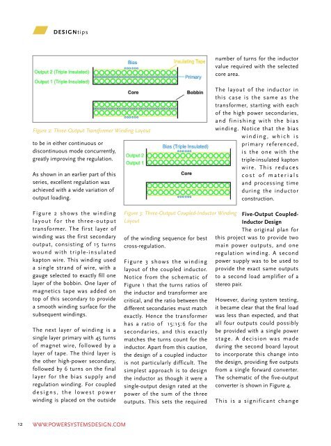
Figure 2: Three-Output Transformer Winding Layout<br />
to be in either continuous or<br />
discontinuous mode concurrently,<br />
greatly improving the regulation.<br />
As shown in an earlier part of this<br />
series, excellent regulation was<br />
achieved with a wide variation of<br />
output loading.<br />
Figure 2 shows the winding<br />
layout for the three-output<br />
transformer. The first layer of<br />
winding was the first secondary<br />
output, consisting of 15 turns<br />
wound with triple-insulated<br />
kapton wire. This winding used<br />
a single strand of wire, with a<br />
gauge selected to exactly fill one<br />
layer of the bobbin. One layer of<br />
magnetics tape was added on<br />
top of this secondary to provide<br />
a smooth winding surface for the<br />
subsequent windings.<br />
The next layer of winding is a<br />
single layer primary with 45 turns<br />
of magnet wire, followed by a<br />
layer of tape. The third layer is<br />
the other high-power secondary,<br />
followed by 6 turns on the final<br />
layer for the bias supply and<br />
regulation winding. For coupled<br />
designs, the lowest power<br />
winding is placed on the outside<br />
Figure 3: Three-Output Coupled-Inductor Winding<br />
Layout<br />
of the winding sequence for best<br />
cross-regulation.<br />
Figure 3 shows the winding<br />
layout of the coupled inductor.<br />
Notice from the schematic of<br />
Figure 1 that the turns ratios of<br />
the inductor and transformer are<br />
critical, and the ratio between the<br />
different secondaries must match<br />
exactly. Hence the transformer<br />
has a ratio of 15:15:6 for the<br />
secondaries, and this exactly<br />
matches the turns count for the<br />
inductor. Apart from this caution,<br />
the design of a coupled inductor<br />
is not particularly difficult. The<br />
simplest approach is to design<br />
the inductor as though it were a<br />
single-output design rated at the<br />
power of the sum of the three<br />
outputs. This sets the required<br />
number of turns for the inductor<br />
value required with the selected<br />
core area.<br />
The layout of the inductor in<br />
this case is the same as the<br />
transformer, starting with each<br />
of the high power secondaries,<br />
and finishing with the bias<br />
winding. Notice that the bias<br />
winding, which is<br />
primary referenced,<br />
is the one with the<br />
triple-insulated kapton<br />
wire. This reduces<br />
cost of materials<br />
and processing time<br />
during the inductor<br />
construction.<br />
Five-Output Coupled-<br />
Inductor <strong>Design</strong><br />
The original plan for<br />
this project was to provide two<br />
main power outputs, and one<br />
regulation winding. A second<br />
power supply was to be used to<br />
provide the exact same outputs<br />
to a second load amplifier of a<br />
stereo pair.<br />
However, during system testing,<br />
it became clear that the final load<br />
was less than expected, and that<br />
all four outputs could possibly<br />
be provided with a single power<br />
stage. A decision was made<br />
during the second board layout<br />
to incorporate this change into<br />
the design, providing five outputs<br />
from a single forward converter.<br />
The schematic of the five-output<br />
converter is shown in Figure 4.<br />
This is a significant change<br />
Figure 4: Redesigned Forward<br />
Converter with Five Coupled-<br />
Inductor Outputs<br />
to the project, but one which<br />
provides substantial savings<br />
in parts, board area, and cost.<br />
The risk is in whether the tight<br />
cross-regulation is lost with more<br />
outputs. The new design also<br />
presents something of a technical<br />
challenge during the board<br />
layout. One of the significant<br />
complications of coupledinductor<br />
designs is managing<br />
the multiple connections of the<br />
transformer, the inductor,<br />
and the rectifier diodes on<br />
the printed circuit board.<br />
The extra outputs also<br />
present significant changes<br />
to the transformer and<br />
inductor designs. There are<br />
now a total of six windings<br />
in the transformer, and<br />
changes must be made to<br />
accommodate the extra<br />
complexity. Figure 5 shows the<br />
winding layout of the transformer.<br />
The first two secondaries are<br />
wound bifilar with each other to<br />
exactly fill the layer with 13 turns<br />
on each secondary of magnet<br />
wire.<br />
The turns count was reduced<br />
because the primary layer could<br />
no longer accommodate the<br />
same 45 turns as before in the<br />
bobbin. With more secondaries,<br />
it made better manufacturing<br />
sense to use triple-insulated<br />
Figure 5: Five-Output Transformer Winding Layout<br />
wire for the primary rather than<br />
the secondaries. Only 38 turns<br />
could fit in the layer neatly. This<br />
POWER SYSTEMS DESIGN JULY/AUGUST 2011<br />
reduced turns count raises the<br />
core excitation, and the switching<br />
frequency must also be raised<br />
slightly to 250 kHz from 200 kHz<br />
in order to avoid saturation of<br />
the transformer.<br />
After the primary is wound, the<br />
remaining two secondaries are<br />
placed on top of this, wound<br />
bifilar with each other. Five turns<br />
of the bias winding complete the<br />
transformer design.<br />
The secondary turns ratio of the<br />
transformer is now 13:13:5, and<br />
this ratio must be maintained<br />
exactly in the inductor. For the<br />
previous inductor design, 15<br />
turns were used in the inductor<br />
main outputs, but this pushed<br />
the design hard in terms of flux<br />
level, and only 20 µH inductance<br />
could be used, resulting in<br />
significant output ripple.<br />
With the reduced power<br />
requirements observed in the<br />
system testing, a decision was<br />
made to raise the turns count<br />
on the main output to 26. This<br />
allowed a larger inductance of<br />
30 µH with a reduced core flux<br />
WWW.POWERSYSTEMSDESIGN.COM WWW.POWERSYSTEMSDESIGN.COM<br />
13