Testing Virtual ECUs - Power Systems Design
Testing Virtual ECUs - Power Systems Design
Testing Virtual ECUs - Power Systems Design

You also want an ePaper? Increase the reach of your titles
YUMPU automatically turns print PDFs into web optimized ePapers that Google loves.
28<br />
SPECIAL REPORT : AUTOMOTIVE ELECTRONICS<br />
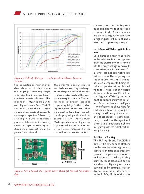
Figure 3: LTC3859A Efficiency vs. Load Current for Different Converter<br />
Sections<br />
buck converters on. With all three<br />
channels on and in sleep mode<br />
the LTC3859A draws only 100µA<br />
which significantly extends battery<br />
run times when in idle mode. This<br />
is done by configuring the part to<br />
enter high efficiency Burst Mode®<br />
operation, were the LTC3859A<br />
delivers short bursts of current to<br />
the output capacitor followed by<br />
a sleep period where the output<br />
power is delivered to the load by<br />
the output capacitor only. Figure 2<br />
shows the conceptual timing diagram<br />
of how this works.<br />
The Burst Mode output ripple is<br />
load independent, only the length<br />
of the sleep intervals will change.<br />
In sleep mode, much of the internal<br />
circuitry is turned off except<br />
for the critical circuitry needed to<br />
respond quickly, further reducing<br />
its quiescent current. When<br />
the output voltage drops enough,<br />
the sleep signal goes low and the<br />
controller resumes normal Burst<br />
Mode operation by turning on the<br />
top external MOSFET. Alternatively,<br />
there are instances when the<br />
user will want to operate in forced<br />
Figure 4: Size & Layout of LTC3859A Demo Board (a) Top and (b) Bottom<br />
sides<br />
continuous or constant frequency<br />
pulse skipping mode at light load<br />
currents. Both of these modes<br />
are easily configurable, will have<br />
a higher quiescent current and a<br />
lower peak to peak output ripple.<br />
Load-Dump/Efficiency/Solution<br />
Size<br />
Load dump is a term that refers<br />
to the inductive kick that happens<br />
after the starter motor is turned<br />
off. This surge voltage is normally<br />
clamped to 36 volts maximum for<br />
a 12 volt lead acid automotive type<br />
battery system. This surge requires<br />
the controller, MOSFETs and associated<br />
components being capable<br />
of operating at the clamped<br />
voltage. These higher voltage<br />
devices (such as 40V MOSFETs)<br />
can degrade efficiency and care<br />
must be taken to minimize this effect.<br />
Based on the circuit in Figure<br />
1, the efficiency is above 92% for<br />
each rail as shown in Figure 3. For<br />
clarity the efficiency of each buck<br />
and boost section is show separately.<br />
In addition, the layout and<br />
circuit size for this circuit is shown<br />
in Figure 4 with the tallest part being<br />
4.8mm high.<br />
Soft Start or Tracking<br />
The TRACK/SS1 and TRACK/SS2<br />
pins of the two buck controllers<br />
can be used for adjusting the soft<br />
start turn-on time or to track two<br />
(or more) supplies with Coincident<br />
or Ratiometric tracking during<br />
start up. These associated curves<br />
are shown in Figure 5 and is accomplished<br />
by putting a resistor<br />
divider from the master supply,<br />
to the TRACK/SS pin of the slave<br />
At higher temperatures, or in cases<br />
where the internal power dissipation<br />
causes excessive self heating<br />
on chip, the over temperature<br />
shutdown circuitry will shut down<br />
the LTC3859A. When the junction<br />
temperature exceeds approximately<br />
170°C, the over temperature<br />
circuitry disables the on-board<br />
bias LDO, causing the bias supply<br />
POWER SYSTEMS DESIGN JULY/AUGUST 2011<br />
Figure 5: LTC3859A Output Voltage Tracking: (a) Coincident Tracking and (b) Ratiometric Tracking<br />
supply.<br />
to drop to zero volts and effective ler. Combined with two synchro-<br />
shutting down the entire LTC3859A nous step-down controllers, ideal<br />
in an orderly manner. Once the for powering many automotive<br />
junction temperature drops back electronic devices, the LTC3859A<br />
to approximately 155°C, the LDO maintains regulation for all output<br />
turns back on.<br />
voltages during an engine restart.<br />
Conclusion<br />
The LTC3859A provides a solution<br />
by boosting the battery voltage to<br />
a safe operating level with is onboard<br />
synchronous boost control-<br />
Author: Bruce Haug<br />
Senior Product Marketing Engineer<br />
Linear Technology Corporation<br />
www.linear.com<br />
WWW.POWERSYSTEMSDESIGN.COM WWW.POWERSYSTEMSDESIGN.COM<br />
29