LP-PLCC-44 PIN
LP-PLCC-44 PIN
LP-PLCC-44 PIN

You also want an ePaper? Increase the reach of your titles
YUMPU automatically turns print PDFs into web optimized ePapers that Google loves.
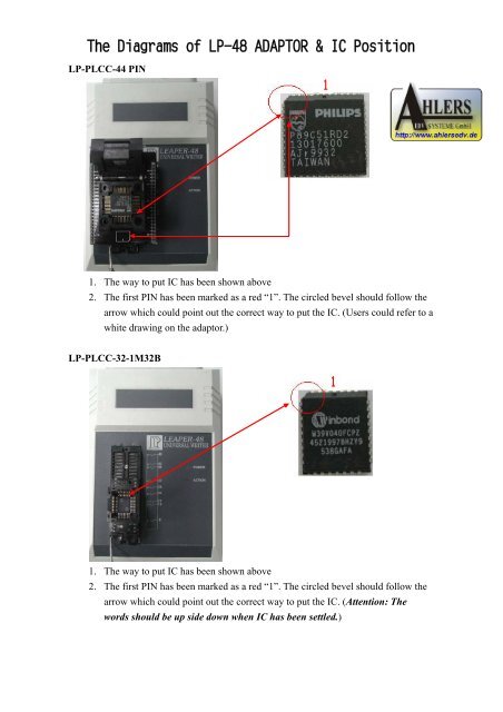
The Diagrams of <strong>LP</strong>-48 ADAPTOR & IC Position<br />
<strong>LP</strong>-<strong>PLCC</strong>-<strong>44</strong> <strong>PIN</strong><br />
1. The way to put IC has been shown above<br />
2. The first <strong>PIN</strong> has been marked as a red “1”. The circled bevel should follow the<br />
arrow which could point out the correct way to put the IC. (Users could refer to a<br />
white drawing on the adaptor.)<br />
<strong>LP</strong>-<strong>PLCC</strong>-32-1M32B<br />
1. The way to put IC has been shown above<br />
2. The first <strong>PIN</strong> has been marked as a red “1”. The circled bevel should follow the<br />
arrow which could point out the correct way to put the IC. (Attention: The<br />
words should be up side down when IC has been settled.)
The Diagrams of <strong>LP</strong>-48 ADAPTOR & IC Position<br />
<strong>LP</strong>-<strong>PLCC</strong>-28 <strong>PIN</strong><br />
1. The way to put IC has been shown above<br />
2. The first <strong>PIN</strong> has been marked a red “1”. The circled bevel should follow the<br />
arrow which could point out the correct way to put the IC. (Users could refer to a<br />
white drawing in the adaptor.)<br />
<strong>LP</strong>-SOP-28 <strong>PIN</strong><br />
1. The way to put IC has been shown above<br />
2. The first <strong>PIN</strong> has been marked a red “1”. IC could follow the arrow to put into<br />
the bottom of the adaptor and the circled first <strong>PIN</strong> should be in the upper left<br />
side.
The Diagrams of <strong>LP</strong>-48 ADAPTOR & IC Position<br />
<strong>LP</strong>-SOP-28 <strong>PIN</strong><br />
1. The way to put IC has been shown above<br />
2. The first <strong>PIN</strong> has been marked a red “1”. IC follows the arrow to put into the<br />
bottom of the adaptor and the first <strong>PIN</strong> should be in the upper left side.<br />
<strong>LP</strong>-SOP-16 <strong>PIN</strong><br />
1. The way to put IC has been shown above<br />
2. The first <strong>PIN</strong> has been marked a red “1”. IC follows the arrow to put into the<br />
bottom of the adaptor and the first <strong>PIN</strong> should be in the upper left side.
The Diagrams of <strong>LP</strong>-48 ADAPTOR & IC Position<br />
<strong>LP</strong>-SOP-16<strong>PIN</strong><br />
1. The way to put IC has been shown above<br />
2. The first <strong>PIN</strong> has been marked a red “1”. IC follows the arrow to put into the<br />
bottom of the adaptor and the first <strong>PIN</strong> should be in the upper left side.<br />
<strong>LP</strong>48-TSOP-48S<br />
1. The way to put IC has been shown above.<br />
2. The first <strong>PIN</strong> has been marked a red “1”. The circled bevel follows the arrow<br />
which could point out the way to put the IC. (Users could refer to a white<br />
drawing on the adaptor.)
The Diagrams of <strong>LP</strong>-48 ADAPTOR & IC Position<br />
<strong>LP</strong>48-TSOP56-M<br />
1. The way to put IC has been shown above.<br />
2. The first <strong>PIN</strong> has been marked a red “1”. The circled bevel follows the arrow<br />
which could point out the way to put the IC. (Users could refer to a white<br />
drawing on the adaptor.)<br />
<strong>LP</strong>-TSOP-48 <strong>PIN</strong><br />
1. The way to put IC has been shown above.<br />
2. The first <strong>PIN</strong> has been marked a red “1”. The circled bevel follows the arrow<br />
which could point out the way to put the IC. (Users could refer to a white<br />
drawing on the adaptor.)
The Diagrams of <strong>LP</strong>-48 ADAPTOR & IC Position<br />
<strong>LP</strong>48-VSOP-32S<br />
1. The way to put IC has been shown above.<br />
2. The first <strong>PIN</strong> has been marked a red “1”. The circled bevel follows the arrow<br />
which could point out the way to put the IC. (Users could refer to a white<br />
drawing on the adaptor.)<br />
<strong>LP</strong>48-TSOP-40 <strong>PIN</strong><br />
1. The way to put IC has been shown above.<br />
2. The first <strong>PIN</strong> has been marked a red “1”. The circled bevel follows the arrow<br />
which could point out the way to put the IC. (Users could refer to a white<br />
drawing on the adaptor.)
The Diagrams of <strong>LP</strong>-48 ADAPTOR & IC Position<br />
<strong>LP</strong>-PSOP-<strong>44</strong> <strong>PIN</strong><br />
1. The way to put IC has been shown above.<br />
2. The first <strong>PIN</strong> has been marked a red “1”. IC follows the arrow to put into the<br />
bottom of the adaptor and the first <strong>PIN</strong> should be in the upper left side.<br />
<strong>LP</strong>-WSON8-5*6/6*8<br />
1. The way to put IC has been shown above.<br />
2. The first <strong>PIN</strong> has been marked a red “1”. IC follows the arrow to put into the<br />
bottom of the adaptor and the arrow direction should be as well as the white part<br />
of the adaptor.
The Diagrams of <strong>LP</strong>-48 ADAPTOR & IC Position<br />
<strong>LP</strong>48-QFP-<strong>44</strong> <strong>PIN</strong><br />
1. The way to put IC has been shown above.<br />
2. The first <strong>PIN</strong> has been marked a red “1”. The circled bevel follows the arrow<br />
which could point out the way to put the IC. (Users could refer to a white<br />
drawing on the adaptor.)<br />
DIP 40 <strong>PIN</strong><br />
1. The way to put IC has been shown above.<br />
2. The first <strong>PIN</strong> has been marked a red “1”. IC follows the arrow to put into the<br />
bottom of the adaptor and the first <strong>PIN</strong> should be in the upper left side.
The Diagrams of <strong>LP</strong>-48 ADAPTOR & IC Position<br />
DIP 8 <strong>PIN</strong><br />
1. The way to put IC has been shown above.<br />
2. The first <strong>PIN</strong> has been marked a red “1”. IC follows the arrow to put into the<br />
bottom of the adaptor and the first <strong>PIN</strong> should be in the upper left side.<br />
<strong>LP</strong>-SDIP-42 <strong>PIN</strong><br />
1. The way to put IC has been shown above.<br />
2. The first <strong>PIN</strong> has been marked a red “1”. IC follows the arrow to put into the<br />
bottom of the adaptor and the first <strong>PIN</strong> should be in the upper side.