LP-PLCC-44 PIN
LP-PLCC-44 PIN
LP-PLCC-44 PIN

You also want an ePaper? Increase the reach of your titles
YUMPU automatically turns print PDFs into web optimized ePapers that Google loves.
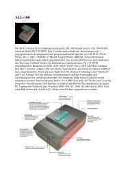
The Diagrams of <strong>LP</strong>-48 ADAPTOR & IC Position<br />
<strong>LP</strong>-SOP-28 <strong>PIN</strong><br />
1. The way to put IC has been shown above<br />
2. The first <strong>PIN</strong> has been marked a red “1”. IC follows the arrow to put into the<br />
bottom of the adaptor and the first <strong>PIN</strong> should be in the upper left side.<br />
<strong>LP</strong>-SOP-16 <strong>PIN</strong><br />
1. The way to put IC has been shown above<br />
2. The first <strong>PIN</strong> has been marked a red “1”. IC follows the arrow to put into the<br />
bottom of the adaptor and the first <strong>PIN</strong> should be in the upper left side.