Test & Measurement - Chauvin-Arnoux i Skandinavien
Test & Measurement - Chauvin-Arnoux i Skandinavien
Test & Measurement - Chauvin-Arnoux i Skandinavien

Create successful ePaper yourself
Turn your PDF publications into a flip-book with our unique Google optimized e-Paper software.
ELECTRICAL TESTING AND SAFETY<br />
Electrical installation testing<br />
The risks linked to incorrect use of electricity may include:<br />
-life-threatening danger for people,<br />
-threat of damage to electrical installations and property,<br />
-harmful effects on systems operation and equipment life spans.<br />
So the purpose of electrical installation testing is primarily to ensure that people<br />
and goods are kept safe and are protected in the event of a fault. It also facilitates<br />
preventive maintenance of installations, preventing serious faults which might prove<br />
expensive (production shutdown, etc.).<br />
To guarantee people's safety with regard to these installations and the electrical<br />
equipment connected to them, standards have naturally been developed and updated<br />
to take changes into account. The IEC 60364 standard and its various national<br />
equivalents published in each European country, such as NF C 15-100 in France or<br />
VDE 100 in Germany, specify the requirements concerning electrical installations<br />
in buildings. Chapter 6 of this standard describes the requirements for testing the<br />
compliance of an installation.<br />
The effectiveness of the safety measures implemented can only be guaranteed if<br />
regular tests prove they are operating correctly. This is why the standards cover not<br />
only the initial verifications when installations are commissioned, but also periodic<br />
testing whose frequency depends on the type of installation and equipment, its use<br />
and the legislation in the country involved. In addition, the tests must be carried out<br />
with measurement instruments that comply with the IEC 61-557 European standard<br />
ensuring user safety and reliable measurements.<br />
The electrical testing is divided into 2 parts:<br />
1. Visual inspection to guarantee that the installation complies with the safety<br />
requirements (presence of an earth electrode, protective devices, etc.) and does<br />
not show any visible evidence of damage.<br />
2. <strong>Measurement</strong>s<br />
There are 4 main measurements required:<br />
1. Earth<br />
2. Continuity<br />
3. Insulation<br />
4. <strong>Test</strong>s of protective devices<br />
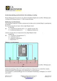
1. EARTH<br />
To guarantee safety on residential or industrial electrical installations, there must be<br />
an earth electrode.<br />
If there is no earth electrode, it may endanger people's lives and damage electrical<br />
installations and property.<br />
When a large enough area is available to set up stakes, you should measure the earth<br />
with the traditional 3-pole method, also known as the 62 % method.<br />
When the 62 % method is not applicable, however, other methods can be used.<br />
There are many methods for measuring the earth, some more suitable than others,<br />
depending on the neutral system, the type of installation (residential, industrial,<br />
urban, rural, etc.), the possibility of cutting off the power, the area available for<br />
planting stakes, etc.<br />
2. CONTINUITY<br />
The purpose of continuity measurement is to check the continuity of the protective<br />
conductors and the main and supplementary equipotential bonds. The test is carried<br />
out using a measurement instrument capable of generating a no-load voltage of 4 to<br />
24 V (DC or AC) with a minimal current of 200 mA.<br />
The resistance measured must be lower than a threshold specified by the standard<br />
applicable to the installation tested, which is usually 2 Ω. As the resistance value is<br />
low, the resistance of the measurement leads must be compensated, particularly if<br />
very long leads are used.<br />
3. INSULATION<br />
Good insulation is essential to prevent electric shocks. This measurement, usually<br />
carried out between active conductors and the earth, involves injecting a DC voltage,<br />
measuring the current and thus determining the insulation resistance value.<br />
The power must be switched off and the installation must be disconnected before<br />
performing this test to ensure that the test voltage will not be applied to other equipment<br />
electrically connected to the circuit to be tested, particularly devices sensitive<br />
to voltage surges.<br />
According to the IEC 60364 standard, the minimum insulation resistance values<br />
must be as follows:<br />
Rated voltage of circuit DC test voltage Insulation resistance<br />
V V MΩ<br />
LV secondary switchboard<br />
or LV main switchboard<br />
250 ≥ 0.5<br />
Less than or equal to 500 V<br />
including LV main switchboard<br />
500 ≥ 1.0<br />
Greater than 500 V 1,000 ≥ 1.0<br />
4. TESTS OF PROTECTIVE DEVICES<br />
- Fuses / Circuit-breakers<br />
To check the specifications of the protective devices such as fuses or circuitbreakers,<br />
a fault loop impedance measurement is carried out to calculate the corresponding<br />
short-circuit current. A visual inspection can then be used to check that<br />
the sizing is correct.<br />
- Residual current devices (RCDs)<br />
RCDs, which detect earth leakage currents, can be tested using two methods:<br />
- the basic test, also called a pulse test, which determines the trip time (in<br />
milliseconds)<br />
- the step test, which determines the trip time and trip current, thus detecting any<br />
RCD ageing.<br />
Page z 38