SXR Technical Design Report - Stanford University
SXR Technical Design Report - Stanford University
SXR Technical Design Report - Stanford University

Create successful ePaper yourself
Turn your PDF publications into a flip-book with our unique Google optimized e-Paper software.
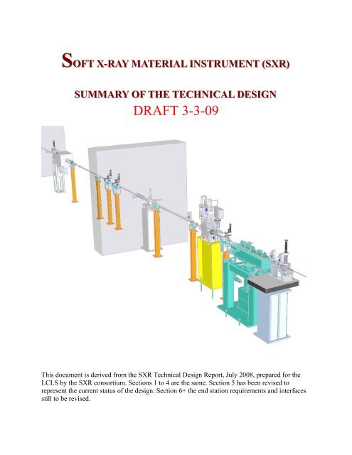
SOFT X--RAY MATERIAL INSTRUMENT ((<strong>SXR</strong>))<br />
SUMMARY OF THE TECHNICAL DESIGN<br />
DRAFT 3-3-09<br />
This document is derived from the <strong>SXR</strong> <strong>Technical</strong> <strong>Design</strong> <strong>Report</strong>, July 2008, prepared for the<br />
LCLS by the <strong>SXR</strong> consortium. Sections 1 to 4 are the same. Section 5 has been revised to<br />
represent the current status of the design. Section 6+ the end station requirements and interfaces<br />
still to be revised.
OUTLINE <strong>SXR</strong> - Summary of the <strong>Technical</strong> <strong>Design</strong>:<br />
Page<br />
1. Introduction 3<br />
2. Scientific Program 4<br />
2.1 Pump-Probe Ultrafast Chemistry 4<br />
2.2 Clusters as new Materials 5<br />
2.3 Magnetic Imaging 6<br />
2.4 X-ray Scattering Spectroscopy on Strongly Correlated Materials 8<br />
2.5 High-Resolution Ultrafast Coherent Imaging 9<br />
3. Science Driven Requirements 11<br />
3.1 Experimental stations 11<br />
3.2 Monochromator 11<br />
3.3 Focusing optics 12<br />
3.4 Diagnostics 12<br />
3.5 Laser systems 12<br />
4. Optical design 14<br />
4.1 Optical layout 14<br />
4.2 Optical elements 14<br />
4.3 Raytracing, energy resolution and efficiency 17<br />
5. Instrument Layout 20<br />
5.1 Instrument Configuration 20<br />
5.2 Single Pulse Shutter 23<br />
5.3 Transmission Sample Station 23<br />
5.4 Monochromator 24<br />
5.5 Zero Order Stop and Grating Apertures 24<br />
5.6 Exit Slit Collimators 24<br />
5.7 Exit Slits 25<br />
5.8 Spectrograph Detector 25<br />
5.9 Photon Stopper 25<br />
5.10 Intensity Monitors 26<br />
5.11 Refocusing Mirrors 26<br />
5.12 Experimental End Station 27<br />
5.13 Optical Pump Laser Transport 28<br />
Appendix: C Descriptions of experimental chambers including detectors from groups that<br />
propose to bring systems.<br />
xx<br />
2
1. INTRODUCTION<br />
The Linac Coherent Light Sources (LCLS) is building the first x-ray Free Electron Laser (FEL) where light is<br />
scheduled to be delivered in August 2009. The facility will operate in the wave length range of 1.5 nm-0.15 nm (800<br />
eV-8 KeV). The proposed soft x-ray imaging and pump-probe x-ray spectroscopy program on materials was<br />
approved by the LCLS Scientific Advisory Committee (SAC) in 2006, and space was allocated in the LCLS near<br />
hall for the accompanying instruments. Due to budget constraints, the materials soft x-ray program did not receive<br />
any instrumentation funding from LUSI. We here propose a plan to move forward with the soft x-ray program by<br />
constructing an instrument that contains a monochromator, refocusing optics and various locations where<br />
experimental endstations can utilize the beam in the soft x-ray energy regime.<br />
In order to fund, design and construct the beam line we have formed a consortium with members from the<br />
<strong>Stanford</strong> Institute of Material and Energy Sciences (SIMES), the Advanced Light Source (ALS), <strong>University</strong> of<br />
Hamburg-DESY, Cener for Free Electron Lasers (CFEL) in Hamburg and BESSY in Berlin. The consortium will<br />
serve as a central hub for a broader scientific community with interest in utilizing the unique capabilities of the<br />
LCLS in the soft x-ray regime. The consortium and various collaborators will also bring different endstations and<br />
detectors to the instrument for the experimental program that can also be utilized by the general users.<br />
Since LCLS will be delivering light at longer wave length in its early operation and the completion of several<br />
LUSI instruments is delayed it is essential that instruments exists that can make use of the early LCLS beam. We<br />
therefore plan to move forward in a timely fashion with this effort with the goal to have an instrument ready in late<br />
summer of 2009. In the following we will describe the science, parameters, optical and technical design of the<br />
instrument. We will in the appendix include a short description of the various experimental endstations that will be<br />
brought to the instrument and letters of intent from the broader scientific community demonstrating their interest.<br />
3
2. SCIENTIFIC PROGRAM<br />
2.1 Pump-Probe Ultrafast Chemistry<br />
The ultimate goal in chemistry and physical chemistry is to understand on a fundamental level how bonds break<br />
and reform during chemical reactions. In many cases we arrive at simple pictures of electron motion with respect to<br />
electron pair redistributions or electrostatic interactions along a reaction path. For many systems bonding can be<br />
understood in terms of molecular orbitals and reactivity in dynamical rearrangements of different molecular states.<br />
Such knowledge provides the basis for the understanding of chemical trends and prediction of chemical reactivity<br />
for chemical compounds. Since the excitation and probe steps with conventional optical lasers involve valence<br />
electrons that are delocalized over many atomic centers it is difficult to study complex systems. Unprecedented<br />
insight into chemical reaction dynamics would be gained by probing exactly the atomic site involved. X-ray<br />
spectroscopies can directly access molecular orbital changes associated with or even during chemical reactions. In<br />
particular, accessing core levels in the soft x-ray regime with spectroscopy opens up new prospects to study timeresolved<br />
changes in the electronic structure of complex systems containing the essential elements C, O and N or 3dmetal<br />
atoms. Detailed insight into surface reactions, catalysis, hydrogen-bonded systems and aqueous solutions can<br />
be expected.<br />
Figure 0-1. Schematic illustration of X-ray Spectroscopy. Here, the radiative decay of a core-hole in N 2<br />
adsorbed on a Ni surface by x-ray emission spectroscopy is shown. In addition to elemental sensitivity the<br />
method provides specificity to different chemical sites as shown in this example.<br />
X-ray spectroscopy has the unique ability to provide an atom-specific probe of the electronic structure. In x-ray<br />
emission spectroscopy (XES) the atomic or elemental sensitivity arises from the filling of a core hole by valence<br />
electrons from the same atomic site. In addition, core-level energy shifts (often denoted chemical shifts) connected<br />
with different environments allow for selective probing of chemically non-equivalent atoms (Figue 0-1). The final<br />
state of the x-ray emission process is a valence-hole state similar to the final state in valence band photoemission<br />
with the unique feature that the valence electronic structure is projected onto a specific atom. Notably, selection<br />
rules of XES, and similarly of X-ray photoelectron spectroscopy (XPS), in conjunction with variation of polarization<br />
4
vector of the incident light or angle-resolved detection of electrons allows to access molecular orbital symmetry and<br />
associated bond geometry. In addition, XPS can be uniquely tuned to high surface sensitivity, which is particularly<br />
desirable when studying interfaces, including the aqueous/vacuum interface. Resonant excitation and Auger electron<br />
spectroscopy gives unique access to the electronic structure of atoms and molecules in the gas phase, on surfaces<br />
and in liquids and solids. Some of the projects planned here are described in further detail in the following:<br />
Surface Reactions and Catalysis: The microscopic understanding of heterogeneous catalysis requires a<br />
detailed understanding of the dynamics of elementary processes at surfaces including adsorption, formation of<br />
different intermediates, and desorption. These can be initiated by an ultrashort (optical) laser pulse, and the evolving<br />
product can be uniquely probed with XES and XPS using FEL soft x-ray pulses at a given time delay. Charge and<br />
energy transfer processes, for instance between an adsorbate and the (catalytic) substrate, can thus be studied with<br />
high site-selectivity and high temporal resolution. Likewise, we expect to identify and to characterize chemical<br />
bonding in short-lived reaction intermediates by transient changes of the electronic structure, from which kinetic<br />
models with an unprecedented level of detail can be derived.<br />
Hydrogen Bonding, Radiation and Aqueous Solution Chemistry: Water is the key species for our existence<br />
on earth, and it is involved in nearly all biological, geological, and chemical processes. Knowledge about the<br />
hydrogen-bonded network structure in liquid water is essential for understanding its unusual chemical and physical<br />
properties. Infrared and optical excitations will be used to induce changes in the hydrogen bonding network, and to<br />
initiate reactions of hydrated molecules. Moreover, on a pratical level, radiation damage of concentrated electrolyte<br />
solutions, relevant for fuel storage, involves the anions interacting with ionizing radiation. To give another example,<br />
low-energy electrons created upon laser irradiation may attach to DNA bases in aqueous environment. Dissociative<br />
electron attachment is a major cause of strand breaks in DNA. Hydrogen-bond dynamics, solute-solvent interactions,<br />
and the interplay of electronic and nuclear dynamics during chemical reactions in solution will be accessible with<br />
time-resolved optical pump and x-ray probe spectroscopy. Techniques include XAS, XES, and XPS measurements;<br />
the latter will be performed in conjunction with the liquid microjet technique.<br />
Warm Dense Matter: Warm Dense Matter refers to the region of the density-temperature phase-space<br />
between solids and plasmas, where the standard theories of condensed matter physics and/or plasma statistical<br />
physics are invalid. [x] These states of matter are of broad interest, as similar conditions of high temperatures and<br />
pressures exist in planetary interiors and in shock compressed matter. Further, there is an incomplete understanding<br />
of how materials damage under Free Electron Laser (FEL) irradiation. A femtosecond optical or FEL pulse will<br />
isochorically heat the sample. The x-ray emission will yield information about the occupied density of states. The<br />
objective is to develop a quantitative understanding of the electronic structure of materials at solid densities and<br />
temperatures of several 1000 ˚K.<br />
x. T. Ao, Y. Ping, K. Widmann, D.F. Price, E. Lee, H. Tam, P.T. Springer and A. Ng, Phys. Rev. Lett. 96, 55001<br />
(2006).<br />
2.2 Clusters as new Materials<br />
Materials assembled atom by atom offer the chance to create new materials with controlled but as yet<br />
unprecedented new properties. In the nanometer size range, new electronic, optical, chemical, magnetic or even<br />
mechanical properties arise due to the effects of the quantized nature of the electronic interactions. Thus, as far as<br />
the development of the novel materials is concerned, the properties of these particles are not predictable by scaling<br />
laws. In this size range every atom counts, i.e. adding or removing just a single atom from the particle will result in<br />
different materials properties. One of the most prominent examples of this kind are the materials formed by<br />
condensing C 60 or related fullerenes into solids bound by van der Waals forces. These purely carbon based solids<br />
exhibit distinctly different properties from diamond or graphite, the other known solid carbon materials.<br />
LCLS offers the unique opportunity to study both the electronic properties as well as the actual atomic structure<br />
of individual mass selected particles with an exactly defined number of atomic constituents. The pulse properties of<br />
5
the LCLS source are required for these studies, since cluster production coupled with mass selection results in a<br />
highly diluted target density. The electronic properties will be accessible by studying the Auger spectrum following<br />
the creation of a core hole, whereas the atomic arrangement will be studied by core level photoemission (XPS) and<br />
(N)EXAFS, once the photon energy at LCLS can be readily tuned. For non-resonant Auger spectroscopy the exact<br />
photon energy does not need to be determined, as long as it is sufficiently high above the core electron absorption<br />
threshold. For XPS the monochromator running in spectrograph mode is required, since the photon energy and<br />
photon lineshape need to be recorded for each LCLS pulse individually together with the XPS spectrum.<br />
Initially in these experiments we will concentrate on the characterization of particles with controlled magnetic<br />
and/or chemical properties.<br />
Control of the magnetic properties of nanoparticles, The control of the properties of magnetic nanoparticles is<br />
crucial for applications ranging from to data storage to cancer treatment. Under basic science aspects, it is intriguing<br />
to note that all atoms, except the rare gases, exhibit magnetism (Hund’s rule). Thus, in the form of well defined<br />
clusters, even elements such as Al form magnetic particles. As extended solids, on the contrary, only the latter part<br />
of the transition metals and the f-electron systems are magnetic. In general, the magnetic moments of clusters are<br />
larger than in the corresponding solids, whereas the temperature, below which magnetic order is stabilized, is lower.<br />
In summary, there are many degrees of freedom to design the magnetic properties of nanoparticles by controlling the<br />
exact size and composition, whereby not only metals, but also oxides are interesting candidates.<br />
Control of the chemical properties of nanoparticles Not only transition metals and their oxides are interesting<br />
candidates as catalysts, but also small Au and Ag clusters and their oxides exhibit quite a high catalytic activity, for<br />
example in various oxidation reactions. Again, the electronic structure of individual mass selected nanoparticles will<br />
be probed by (resonant) Auger spectroscopy and XPS to elucidate not only the particle properties but also the<br />
chemical bonding of adsorbates, while pump-probe spectroscopy will give insight into photo-chemical reaction<br />
cycles.<br />
2.3 Magnetic Imaging<br />
One of important topics of physics is the study of phase transitions, where structural, electronic, or magnetic<br />
properties undergo discontinuous or continuous changes. Powerful symmetry and statistical concepts have been<br />
developed to describe such phase transitions, and corresponding scattering and thermodynamic measurements have<br />
been used for experimental verifications. Such approaches are quite successful and satisfactory to many.<br />
Complementary and equally powerful, the conceptualization of a simple physical picture in the real space has played<br />
an important role in the formulation of physical understanding of many phenomena. This method of direct<br />
representation, however, has not received equal recognition perhaps due to the lack of corresponding experimental<br />
techniques until now. By combining the powerful Fourier Transform Holography (FTH) imaging technique with<br />
LCLS' high brightness, short pulse structure, and fully transverse coherence, the dynamics of magnetic fluctuations<br />
and magnetization relaxation processes can be visualization at extremely fast time scales and at nm resolutions.<br />
This soon-to-be-established new capabilities will not only provide direct experimental proof of the symmetry and<br />
statistical concepts in magnetic phase transitions, but will also have far-reaching impact beyond magnetism in the<br />
studies of critical phenomenon such as other order/disorder transitions or the demixing of binary alloys.<br />
6
Figure 0-2. Illustration of X-ray Fourie Transform Holography experiment.<br />
The proposed experiments will de designed to investigate the critical fluctuations occurring at magnetic phase<br />
transitions. An initial LCLS experiment will demonstrate the existence of magnetic spin blocks by taking snap shot<br />
pictures on a time scale faster than the fluctuations. The next step will be to study the spin block dynamics by<br />
recording a series of such pictures at well-defined delay times. For imaging of the magnetic spin blocks a newly<br />
developed lensless imaging technique will be used. These experiments, however, would not be possible without the<br />
LCLS' ultra-bright, ultra-short, and fully coherent x-ray pulses. Key properties and implications of the proposed<br />
experiment are:<br />
Single x-ray pulse imaging: A single LCLS pulse will be sufficient to obtain an image of the instantaneous<br />
magnetic domain structure which is expected to be static on the time scale set by the ultra-short x-ray pulse length<br />
(230 fs), even close to the phase transition.<br />
50 nm spatial resolution or better: It has been demonstrated that a 50 nm spatial resolution can be achieved<br />
with the newly developed lensless x-ray imaging technique which will take full advantage of the unprecedented full<br />
coherence of LCLS x-ray pulses. Subsequent phase retrieval may improve this to near-wavelength limited spatial<br />
resolution.<br />
Dynamics of critical fluctuations: To image the fluctuation dynamics we will split the beam and produce<br />
consecutive x-ray pulses with a well defined time separation at the sample. From each pulse we will obtain an<br />
image of the magnetic domain structure, using a scheme discussed below, and thus resolve the dynamics occurring<br />
on a femtosecond to nanosecond time scale.<br />
Ultrafast, non-deterministic dynamics: It is important to realize that the proposed experiments significantly<br />
differ from today’s ultrafast pump-probe experiments. Such experiments rely on reversibility of the sample to a well<br />
defined state before each pump-probe cycle. In contrast, the critical fluctuations that are the subject of our study are<br />
non-deterministic and their study requires complete images to be recorded in a single shot.<br />
Ultrafast relaxation dynamics: It is clear that once we have demonstrated the feasibility of ultrafast single<br />
shot imaging a whole class of new experiments will become possible. Besides single shot imaging of spontaneously<br />
occurring fluctuations we also envision to study ultrafast relaxation dynamics in pump-probe experiments.<br />
7
2.4 X-Ray Scattering Spectroscopy on Strongly Correlated Materials<br />
Among the current research issues of condensed matter physics, the electronic structure of the strongly correlated<br />
materials is one of the most active topics. In this class of materials, the Coulomb interaction between electrons can<br />
not be ignored, which manifests itself as “strong correlations” acting as a “tuning parameter” to switch the ground<br />
state from one to the other. These collective ground states for different phases are known as “emergent” phenomena<br />
of many body systems, which can not be deduced from any perturbation theory and often involve novel forms of<br />
order.<br />
X-Ray scattering experiments on strongly correlated materials have been performed to probe the charge ordering<br />
and elementary charge/magnetic excitations containing important information of the ground state properties. Recent<br />
theoretical developments show that resonance x-ray scattering can provide rich information on many-body<br />
wavefunctions. Soft x-ray, being sensitive to valence electrons and in the spectral range of important L edges of<br />
transition metals that often are key elements of correlated materials, provide special opportunity. However, so far<br />
most of these experiments were performed in the equilibrium state, which can not provide any information along the<br />
time axis regarding how the electrons form this particular ground state. The exciting opportunity provided by the<br />
<strong>SXR</strong> of LCLS is exactly this missing piece of information along the time axis. Using the high pulse intensity and<br />
ultra-short pulse length, it is possible to perform optical-pump-and-X-ray-probe experiments to study how the<br />
electronic states of strongly-correlated materials relax from an excited state to the ground state. The relaxation<br />
process is closely related to the correlation effect among the electrons and the electronic interactions to other degrees<br />
of freedom; therefore “snap shots” obtained from the pump-probe experiments provide important clues to construct<br />
a microscopic physics picture of the strongly-correlated systems. In addition, x-ray probe experiment also has some<br />
unique advantages, such as element specific information, bulk sensitive signal, and the dynamic structure factors,<br />
which are not accessible by the most common ultrafast optical pump-probe experiments in the visible light regime.<br />
Figure 3 (a) A sketch of the momentum-resolved inelastic scattering experiment chamber. (b) The momentum<br />
transfer covered by different locations of the spectrograph at the Mn L edge. (c) The Fermi surface of La 1-<br />
xSr 1+x MnO 4 and the region which can be covered by this spectrograph with the designed rotary sample stage.<br />
(d) The dispersion of orbital ordering of the La 1-x Sr 1+x MnO 4 .<br />
Three kinds of experiments were proposed for using LCLS to study the physics of the strongly correlated materials:<br />
Absorption experiment: Absorption spectrum reveals the partial density of states of the unoccupied state of<br />
the materials. As a first step, it is important to understand how density of state change after the system been<br />
“pumped” by the optical Laser pulse. It is also an ideal initial experiment to do for the initial operation stage of the<br />
LCLS, since it is not an extremely photon hungry experiment, which can be done using with less powerful pulse and<br />
lower repetition rate. In addition, this absorption experiment would become a routine diagnosis experiment for the<br />
chamber alignment, sample damage assessment and a survey experiments for the resonant scattering experiments.<br />
8
Resonant Elastic Scattering experiment: Charge, spin and orbital order is one of the interesting phenomena in<br />
many strongly correlated electron systems. These orderings, mostly incommensurate to the lattice constant, produce<br />
extra Bragg peaks in the elastic X-ray diffraction pattern. As these orders are often complex and thus relatively<br />
large in real space, making it possible for soft x-ray to have sufficient q to probe the extra Bragg peak. Using <strong>SXR</strong><br />
pump-probe capability of LCLS, one could destroy the charge ordering by the optical pump Laser and probe by the<br />
LCLS X-ray pulse at different delay times after the pump as the system relaxes back to the charging ordering state.<br />
This experiment shall reveal important microscopic information of the charge ordering formation.<br />
Resonant Inelastic X-ray Scattering (RIXS) Experiment: To probe the excitations of the ground state, it is<br />
necessary to record the energy loss of an inelastic scattering process. In addition, the information at different<br />
momentum transfers of the scattering process is also extremely important for the scattering experiments on solids as<br />
it is related to the momenta of these excitations. Time resolved pump-probe RIXS experiments can be used to<br />
measure time evolution of collective modes and thus, information about the dynamics involves in the many-body<br />
excitations that gave the collective modes. In addition, we will also use RIXS to obtain the wave function properties<br />
through various projections to its intermediate states. The pump-probe experiment using the <strong>SXR</strong> shall provide a<br />
description of the wave function evolution from the pumped exciting state to the ground state.<br />
2.5 High-Resolution Ultrafast Coherent Imaging<br />
X-ray microscopy at synchrotron sources is steadily progressing, with the nanofabrication of better zone-plate<br />
lenses and the development of lensless coherent imaging techniques. However, even with cryogenic sample<br />
cooling, radiation damage limits the achievable resolution to about 10 nm. Higher resolution is required to<br />
understand the structure and organization of living (unstained and unsectioned) cells, and would greatly complement<br />
real-time optical fluorescence microscopy to study cell processes, such as cell division, and full function of<br />
components such as the cytoskeleton. Coherent diffractive imaging with intense and ultrashort X-ray pulses could<br />
achieve the required resolution on living cells by recording the scattering information before any structural changes<br />
due to interaction with that pulse. This method of flash imaging has been verified at FLASH. In principle the<br />
resolution should only be limited by the wavelength of the radiation, given the appropriate pulse parameters and size<br />
of the focused pulse. The details of the matter–FEL interaction must be studied to gain an understanding of<br />
achievable resolution limits. Methods must also be developed for 3D imaging of reproducible samples, using<br />
streams of particles in the gas phase or in droplets. These delivery systems, first developed at FLASH, are required<br />
to quickly replenish the sample and allow time-resolved stroboscopic imaging of laser alignment of particles. Also<br />
the coherent diffractive method (with fixed or injected samples) enables the highest spatial resolution of ultrafast<br />
processes in non-periodic systems, such as the study of laser-induced phase transitions in materials. Experiments at<br />
FLASH demonstrated this technique on the study of phase separation in laser-ablation, but the shorter wavelengths<br />
of LCLS are required to achieve the necessary spatial resolution.<br />
Imaging of biological cells beyond radiation damage limits: With the X-ray intensity provided by 5-micron<br />
focusing it will be possible to achieve a single-shot resolution of better than 5 nm. Imaging will be carried out on<br />
cells on thin membranes that can be placed into the beam as well as on cells injected into the LCLS beam.<br />
FEL-matter interactions: Initial experiments will study the effects of damage by collecting coherent patterns<br />
of homogeneous samples (such as polystyrene spheres or nanocrystals) as a function of pulse fluence. In this case,<br />
the scattering pattern immediately gives the pulse-integrated size distribution of the particles, which can be<br />
compared with theory. Nanocrystals of biomolecular complexes (such as PS1) will give the high-resolution<br />
information about the damage of organic material as a function of resolution and pulse fluence.<br />
Time-Delay Holography: This method, tested at FLASH, will be implemented to measure movies of the<br />
interaction and evolution of reproducible samples (such as virus particles) with FEL pulses. The apparatus will<br />
include a reflecting crystal, such as InSb, to direct the pulse back onto the sample. The detector will be placed in a<br />
9
ackscattering geometry. Samples will include layered spherical structures to test methodologies to prolong the<br />
onset of damage.<br />
Laser-matter interactions: A synchronized optical pump pulse will be used for single-shot time-resolved<br />
imaging in materials and stroboscopic imaging of laser-particle interactions (such as laser alignment).<br />
10
3. Science Driven Requirements:<br />
In this section the basic science driven requirements of the beam line, optics and experimental stations for the <strong>SXR</strong><br />
system are described. The proposal is for a monochromatic soft x-ray beam line with two positions for experimental<br />
stations.<br />
3.1 Experimental stations:<br />
The first experimental station shall be up stream of the monochromator in the unfocused beam. The second after the<br />
monochromator for focused beam.<br />
3.1.1 Experimental station position 1:<br />
It is important to allow for an experimental station at a position before the monochromator where x-ray interactions<br />
could be performed in a single shot mode. This is to be a simple chamber to allow transmission experiments on large<br />
samples, > 1mm in diameter. The requirement for absorption spectroscopy is a detector at the monochromator exit<br />
slit. A pump laser is required for pump probe experiments at this position. Ultra-high vacuum,
3.2.3 Pulse stretching:
3.5.1 Pump Laser:<br />
The pump laser should be capable of producing 2mJ/pulse at 120Hz. The pump laser system is defined in Physics<br />
Requirements for LCLS/NEH Laser System, Requirements Document # 1.6-010 rev 0 section 2, 3, 4, 6, 7 and 8. To<br />
summarize it should be capable of delivering 800nm with an energy of up to 3mJ in a pulse ≤50 fs at the sample.<br />
The pump laser shall be synchronized with the LCLS FEL at a repetition rate of 120Hz. The pulse laser should be<br />
synchronized to the LCLS RF with a jitter of ≤100 fs. The delay system should be capable of adjusting the laser<br />
timing by ±1ns with 10fs accuracy. There are some experiments that require 25 mJ/pulse at a 10Hz rate. The<br />
conversion to shorter and longer wave lengths is not required for initial experiments on the <strong>SXR</strong> (section 5 of the<br />
above mention document), but provision should be made to accommodate this at a later date.<br />
3.5.2 Alignment Lasers:<br />
A HeNe alignment laser beam shall be set up coaxial with the FEL beam to facilitate the positioning of samples in<br />
the FEL beam. This laser shall be class IIIa rating or less.<br />
13
4. Optical <strong>Design</strong><br />
4. 1 Optical layout<br />
At synchrotron radiation sources, two of the most successful types of grating monochromators are the<br />
Varied-Line-Spacing grating monochromator (VLS) and the Plane Grating Monochromator (PGM). The VLS<br />
monochromator was developed by Underwood, Koike and coworkers at the Advanced Light Source (ALS). [2] A<br />
spherical mirror produces a converging beam in the vertical plane and a varied-line-spacing grating diffracts the x-<br />
rays onto an exit slit. The variable period of the grating provides additional parameters to keep the focal distance<br />
constant as a function of photon energy and to compensate for aberrations of the mirror. The focal plane is erect,<br />
which is convenient for implementing the spectrometer mode. The photon energy is scanned by a single rotation of<br />
the grating.<br />
The PGM monochromator was developed by Peterson, Follath and Senf at BESSY. [3] In the PGM<br />
monochromator a plane mirror reflects the x-rays onto the grating and an elliptical or spherical mirror focuses the<br />
beam onto the exit slit. The plane mirror provides a variable included angle on the grating, which allows the grating<br />
efficiency to be optimized over a wide photon energy range. The photon energy is scanned by coordinated rotations<br />
of both the plane mirror and grating.<br />
We have chosen the VLS monochromator type because of its simplicity. Only two optical elements are<br />
required, and only the grating rotates. The limited photon energy range of the <strong>SXR</strong> Instrument, 500 to 2000 eV,<br />
would not take advantage of the variable included angle of the PGM monochromator.<br />
Figure 4-1. Optical layout of the <strong>SXR</strong> Instrument.<br />
The optical layout of the <strong>SXR</strong> Instrument is shown in figure 1. Table 1 is a list of the optical elements and<br />
their parameters. The first component is experimental chamber 1, which is a location for samples in the unfocused<br />
non-monochromatic beam. Next, there is the M1 spherical mirror and G1 and G2 plane gratings of the VLS<br />
monochromator. In monochromator mode, an exit slit selects a narrow bandwidth. Alternatively in spectrometer<br />
mode, a detector will measure the dispersed x-ray absorption spectrum. The M2 plane elliptical mirror provides the<br />
horizontal focus in experimental chamber 2. The plane elliptical M3 mirror produces a vertical image of the exit slit<br />
at experimental chamber 2. The experimental chamber 2 provides the experimental environment for monochromatic<br />
and focused pink beam experiments. Endstation 1, the M1 mirror and gratings are in the first hutch of the LCLS<br />
Near Experimental Hall. The rest of the beamline from the exit slit and detector through the experimental chamber<br />
2 are in the second hutch.<br />
4.2 Optical elements<br />
The design of the optical elements adopts characteristics of the LCLS soft x-ray offset mirrors in the Front<br />
End Enclosure. The incidence angle of the mirrors is 89.14o equivalent to a grazing angle of 15 mrad. The mirror<br />
substrates are single crystal silicon, and the preferred optical coating is B4C. Figure 2 shows the reflectivity of B4C<br />
in comparison with other coating materials. The reflectivity of B4C is excellent about 90 % over the whole energy<br />
14
Type<br />
Exp.<br />
Chamber 1<br />
M1 Spherical<br />
mirror<br />
G1, G2 Plane VLS<br />
grating<br />
Detector/<br />
Slit<br />
M2 Bent Elliptical<br />
mirror<br />
M3 Bent Elliptical<br />
mirror<br />
Exp.<br />
chamber 2<br />
Coating and<br />
blank<br />
material<br />
B 4 C-coated<br />
silicon<br />
B 4 C -coated<br />
silicon<br />
B 4 C-coated<br />
silicon<br />
B 4 C-coated<br />
silicon<br />
Dimensions<br />
l x w x t<br />
(mm)<br />
Clear<br />
Aperture<br />
(mm)<br />
Radius<br />
(m)<br />
Figure<br />
error<br />
(μrad)<br />
Roughness<br />
(nm)<br />
Incidence<br />
angle(°)<br />
Grating period<br />
order<br />
Distance<br />
from<br />
source (m)<br />
124<br />
250 x 30 175 x 10 943 0.3 0.4 89.14 - 125.1<br />
220 x 50<br />
x 23<br />
170 x 24 ∞ 0.5 0.4 88.7-88.9 1/100, 1/200<br />
-1<br />
250 x 30 190 x 10 262.8 0.3 0.4 89.14 - 137.4<br />
250 x 30 125 x 10 156 0.4 0.4 89.14 - 137.9<br />
125.4<br />
132.6<br />
139.4<br />
Table 4-1. The optical elements of the <strong>SXR</strong> instrument.<br />
15
1.0<br />
0.8<br />
Reflectivity<br />
0.6<br />
0.4<br />
0.2<br />
B 4<br />
C<br />
C<br />
Si<br />
B<br />
0.0<br />
5 6 7 8 9<br />
1000<br />
2<br />
Photon energy (eV)<br />
Figure 4-2. The reflectivity at 15 mrad grazing angle of B 4 C, C, Si and B.<br />
range of the <strong>SXR</strong> instrument. Boron and Carbon would also give acceptable performance. The incidence<br />
angle and coating materials maintain 2000 eV as the high photon energy limit. Silicon would limit the cut off to<br />
1800 eV. The clear apertures are set to accept a 5 σ footprint of the x-ray beam including a tolerance of 0.5 μrad<br />
rms for the LCLS beam pointing stability. [4] The M1 mirror is polished as a sphere. On the other hand the M2 and<br />
M3 mirrors are polished as flats and then bent into their plane elliptical shapes. The M2 and M3 mirrors need an<br />
elliptical surface in order to eliminate the coma aberration. The coarse grating line densities, 100 and 200 l/mm, are<br />
a consequence of the included angle 2 θ being close to 180 o . It is planned to have both rulings placed on a single<br />
grating substrate. The gratings operate in the negative first diffracted order. The choice of negative order has two<br />
benefits. The larger grazing incidence angle reduces the required length of the grating. The grating in negative<br />
order has magnification, which eases the needed detector spatial resolution. For the distances of the optical elements,<br />
the source position is chosen as 10 m upstream from the end of the undulator. [5]<br />
Figure 4-3a. The LCLS FEL source at 1000 eV.<br />
Figure 4-3b. The x-ray beam at experimental<br />
chamber 1.<br />
16
Figure 4-3c. Photon energies 999.8, 1000 and Figure 4-3d. The monochromatic focus in<br />
1000.2 eV at the detector or exit slit. experimental chamber 2.<br />
4.3 Raytracing, energy resolution and efficiency<br />
Raytracing has been performed to confirm the optical design using the XOP software. Spot<br />
diagrams are displayed in figure 4. The LCLS FEL source at 1000 eV is predicted to be round with a<br />
diameter of 82 μm (fwhm) and a divergence of 8 μrad (fwhm). Compared with third generation<br />
synchrotron sources, the horizontal beam size and the divergence in both dimensions are significantly<br />
smaller. In experimental chamber 1 the unfocused x-ray beam is again round with a diameter of 1 mm<br />
(fwhm). The M1 mirror and VLS gratings G1 or G2 produce a vertical focus, 1.1 mm horizontal by 18 μm<br />
vertical (fwhm), at the exit slit or detector. The spot diagram (3c) shows three different energies 999.8,<br />
1000 and 1000.2 eV at the exit slit. That these three photon energies are well resolved confirms that the<br />
resolution goal of 0.2 eV at 1000 eV is achieved. The M2 and M3 mirrors refocus the x-rays horizontally<br />
and vertically into experimental chamber 2. The predicted monochromatic focus in experimental chamber<br />
2 is between 1 and 2 μm horizontal by 3 μm vertical (fwhm). In the case of the non-monochromatic beam,<br />
the vertical focusing is changed because now the grating has a magnification of unity. For the nonmonochromatic<br />
beam the calculated focus in experimental chamber 2 is nearly round between 1 and 2 μm<br />
in diameter (fwhm). It should be noted that this ray tracing does not include optical fabrication errors.<br />
The tolerances for FEL x-ray optics are quite demanding and beyond what is required for<br />
synchrotron radiation optics. This difficulty can be simply understood by the fact that the FEL and<br />
synchrotron source dimensions are similar but for FELs the first optic is roughly ten times further away;<br />
hence the allowable slope error is reduced by about an order of magnitude.<br />
s<br />
2Δ r ≤ , (1)<br />
T<br />
2<br />
where Δ T is the tangential slope error, r the source distance and s the source dimension. Preserving the<br />
source brightness of the LCLS is challenging.<br />
Optical tolerances are included in table 1 for the slope error and roughness. The figure<br />
specifications for the M1 mirror and G1 and G2 gratings result from the energy resolution goal of 0.2 eV at<br />
1000 eV. The figure tolerance for the M1 mirror is the most difficult because the image created by the M1<br />
mirror is magnified by the grating. The figure specification of the M2 and M3 mirrors is derived from the<br />
required focus in experimental chamber 2, a 10 μm diameter. The B 4 C coatings place an upper limit on the<br />
roughness for spatial periods from 20 nm to 2 μm, the Atomic Force Microscope measurement range. With<br />
higher substrate roughness the B4C coating growth process changes. A specification from Fourier optics<br />
considerations will be added to the mirror and grating specifications.<br />
17
The grating efficiency is the most important factor in determining the overall beamline efficiency.<br />
Efficiency calculations were performed with the GSolver code. [6] The optical constants for the B 4 C<br />
coating were taken from the CXRO website. [7] For the laminar groove profiles, the groove depths and<br />
widths were varied to maximize the efficiency at single photon energies: 800 eV for the 100 line/mm<br />
grating and 1200 eV for the 200 line/mm grating. The optimal groove depths were found to be 19 nm for<br />
the 100 line/mm and 13 nm for the 200 line/mm grating. High peak efficiencies between 0.1 and 0.4 were<br />
calculated. These efficiencies should be related to the low groove densities and the high reflectivity of B 4 C.<br />
The average power in the LCLS FEL radiation is low, 0.2 W, because of the low repetition rate,<br />
120 Hz. On the other hand, the peak power is quite high, 5 GW, as a result of the ultrashort pulses. Optical<br />
damage from the LCLS x-rays was modeled by London et al. [8] Their guideline is to stay below the melt<br />
fluence. The risk of optical damage is reduced by using small grazing angles and low Z coatings. Since the<br />
<strong>SXR</strong> mirrors employ the same incidence angle and coating as the LCLS soft x-ray offset mirrors, these<br />
mirrors should be safe from the damage calculations of these mirrors. An estimate of the absorbed energy<br />
for the M1 mirror is 0.04 eV/atom, well below melting dose of 0.62 eV/atom. The case of the gratings<br />
could be worse because of the larger grazing incidence angle and that a portion of the x-rays strike the<br />
leading edges of the lands at near-normal incidence. However, estimates of both these cases gave an<br />
acceptable dose of 0.05 eV/atom. These damage calculations were performed at 2000 eV, which is the<br />
most difficult case because of the reduced beam divergence. The optics of the <strong>SXR</strong> instrument should not<br />
damage from the FEL radiation.<br />
The exit slit may be also damaged from the LCLS FEL beam, which is vertically focused at this<br />
location. Three cases must be considered: monochromatic beam, zero order and pink beam. For the<br />
monochromatic situation the dose is acceptable, 0.03 eV/atom, because the intensity is reduced by the<br />
dispersion of the different FEL wavelengths in negative first order. This damage consideration does<br />
require that the exit slit blades be made of B 4 C or perhaps another low Z material. The zero order can be<br />
blocked at a small distance downstream of the gratings, where the x-ray beam is not focused. The final and<br />
most difficult case is the undispersed pink beam. Here the dose at the exit slit, 5 eV/atom, is not acceptable.<br />
One solution is to add an aperture upstream, where the FEL beam is large enough and the flux density<br />
below the damage limit. This aperture would need to be aligned to the exit slit and the exit slit would need<br />
to be openable to a larger width than the aperture. An aperture that opens to 2 mm would transit the<br />
dispersed spectrum to the detector for spectroscopy experiments.<br />
Grating optics increase the x-ray pulse duration. This pulse stretching, Δt, results from the extra<br />
optical path, m λ, between groove n and groove n+1, where m is the order of diffraction and λ the x-ray<br />
wavelength. It can be calculated from<br />
t =<br />
Nmλ<br />
c<br />
Δ , (2)<br />
here N is the number of illuminated grooves and c the speed of light. For 800 eV the estimated pulse<br />
stretching is 40 fs, which is well below the predicted LCLS pulse duration of 320 fs. For measurements<br />
with the sample in experimental chamber 1 or in experimental chamber 2 using pink beam, there is no<br />
optical pulse stretching. There are operating modes of the LCLS which will provide shorter pulses. [9]<br />
There should be an angular aperture in the <strong>SXR</strong> instrument in order that the pulse stretching can be reduced<br />
with a corresponding loss in intensity and in energy resolution.<br />
There are existing mechanical designs for monochromators, bendable mirror assemblies and exit<br />
slits at the Advanced Light Source and other synchrotron facilities. It is planned to reuse existing<br />
mechanical designs with minimal modifications for the LCLS <strong>SXR</strong> instrument. Switching between<br />
monochromatic and pink beam may be accomplished in a convenient manner provided by the current,<br />
18
“standard” ALS monochromator chamber design. The chamber is translated horizontally perpendicular to<br />
the beam propagation direction. If the grating surface has ruled and unruled areas, the grating can either<br />
diffract for monochromatic operation or reflect for pink beam operation.<br />
References<br />
1. P. Emma, private communication.<br />
2. Underwood, J.H., and. Koch, J.A, Applied Optics 36, 4913-4921 (1997).<br />
3. H. Petersen, Opt. Commun. 40, 402-406 (1982); R. Follath, Nucl. Instrum. and Meth. A, 467, 418-425<br />
(2001).<br />
4. P. Stefan, private communication.<br />
5. Y. Feng and H. D. Nuhn, private communications. The source distance depends upon the point along the<br />
undulator length where the FEL reaches saturation. 10 m from the downstream end of the undulator is the<br />
nominal saturation point for the LCLS start up parameters at 800 eV.<br />
6. http://www.gsolver.com.<br />
7. http://henke.lbl.gov/optical_constants.<br />
8. R.A. London, R.M. Bionta, R.O. Tatchyn and S. Roesler, SPIE Proceedings 4500, 51-62 (2001).<br />
9. P. Emma et al., Phys. Rev. Lett. 92, 074801 (2004).<br />
19
5. Instrument Layout:<br />
In this section we will describe the constraints on the physical layout of the <strong>SXR</strong> systems and how we<br />
propose to meet the scientific requirements within those constraints. The proposal conforms to the new<br />
AMO experiment location in the first hutch of the Near Experimental Hall (NEH) on the 83 mrad line. The<br />
<strong>SXR</strong> systems are on the 28 mrad line, between the AMO line and the hard x-ray line, with a premonochromator<br />
sample position, M1 mirror and grating system in first hutch. The <strong>SXR</strong> exit slit,<br />
refocusing mirror and end station are in the second hutch.<br />
In the Front End Enclosure (FEE) the M3-S1 or M3-S2 mirrors of the Soft x-ray Optics Mirror System<br />
(SOMS) direct the FEL beam down either the 83 mrad or the 28 mrad lines to the AMO and <strong>SXR</strong><br />
experiments respectively. On each branch there are fixed collimators and insertable photon stoppers in the<br />
FEE that block the beam, so entry can be permitted into the first hutch. Just down stream of the first hutch<br />
wall there is an insertable beam position imaging system and an isolation valve. This terminates the SOMS<br />
vacuum system.<br />
The basic optical layout is presented in section 3. There are several constraints on fitting this optical<br />
design into the NEH. The first is that it does not materially interfere with the program on the AMO<br />
experiment. Both requirements are physical, over space, and operationally for access during operations on<br />
each system. A second is the flux in the FEL beam. Though power is on average low, the flux density in<br />
the FEL beam will damage most materials. This is particularly critical where the beam is focused. The third<br />
requirement is the inclusion of a moderately high resolution monochromator, which essentially requires it<br />
span the first and second hutches.<br />
The AMO group is locating their experiment in the first hutch of the NEH. The <strong>SXR</strong> beam will pass<br />
through the first hutch, horizontally between the AMO experiment and the hard x-ray beam line. The first<br />
experimental station and the monochromator would be located in the first hutch just up stream of the AMO<br />
focusing optics. These would have to be properly shielded for personnel to be in the first hutch while beam<br />
is passing through the <strong>SXR</strong> monochromator into the second hutch. These shielding requirements have not<br />
yet been defined. The controls on the shielding will follow SLAC personnel protection requirements. This<br />
shielding and controls will be required for the <strong>SXR</strong> experiment to run effectively. The hard x-ray beam line<br />
that also passes through the first hutch will be shielded.<br />
The flux density in the FEL beam will damage most materials and is particularly critical where the beam is<br />
focused. Materials of low Z elements have the best properties for surviving in the beam [3]. Collimators<br />
and beam stops are to be fabricated from B 4 C which should not damage in the unfocused FEL beam at this<br />
distance from the source. At approximately 0.12 eV/atom/pulse fatigue sets in and at 0.6 eV/atom/pulse<br />
single shot damage occurs in B 4 C. The fatigue value sets a limit for optics and beam stops that are<br />
continuously or often in the beam. Collimator and apertures that will only see incidental beam strikes are<br />
limited at the higher single shot damage threshold. The monochromator proposed in section 3 focuses, in<br />
one dimension, both the monochromatic and the zero order, white, beam at the exit slit. All materials are<br />
likely to damage in the focused zero order beam at the exit slit. Thus the exit slit must be opened when<br />
zero order light is put through it to prevent damage to the slit blades. This does not substantially limit the<br />
ultimate focus at the second experimental station as the zero order focus is quite small, 1σ ~10μm. An<br />
aperture up stream of this zero order flux density ‘stay clear’ would contain the beam and prevent the<br />
focused zero order beam from striking the open exit slits.<br />
5.1 Instrument Configuration:<br />
The <strong>SXR</strong> proposal is predicated on the inclusion of a monochromator, which essentially requires the<br />
optical system to span the first and second hutches of the NEH. The basic layout is shown in figure 5.1. The<br />
transmission sample position and the monochromator focusing/grating system will be located in the first<br />
hutch along with, but up stream of, the AMO experiments. The <strong>SXR</strong> is laid out to make space for an<br />
extension of AMO experimental systems into the second hutch.<br />
20
Figure 5.1 Proposed layout of the AMO and <strong>SXR</strong> beam line and experimental systems in the NEH. <strong>SXR</strong> in<br />
orange, AMO in purple and XTOD, to down stream hard x-ray experiments, in blue. (Dimensions in m.)<br />
The hutches are roughly 10m in length , 10m in width and 4.5m high. Access is through interlocked doors.<br />
The hutches will also contain the optical tables for the pump and alignment lasers, electronics racks<br />
electrical panels and other utilities. See figures 5.2 A & B. The first hutch is primarily dedicated to the<br />
AMO instrument on the 90mrad branch line (actually 83 mrad from the undulator center line). On the 30<br />
mrad (23mrad) branch line is the <strong>SXR</strong> instrument. In the first hutch the single pulse shutter, the<br />
transmission sample chamber, the monochromator tank, collimators and drift tubes for the <strong>SXR</strong> will be<br />
located. On the 0 mrad line the XTOD, hard x-ray beam line, passes through both hutches 2m from the<br />
back wall. The nominal FEL bean height is 1.4m above the floor.<br />
The <strong>SXR</strong> optical layout has the M1 mirror and grating system just up stream of the AMO experiment<br />
which puts the exit slit, 7.5m down beam, just inside the second hutch. The K-B pair of refocusing mirrors<br />
are in the middle of the hutch with the final focus 1.5m down stream of the center of the M3 mirror. See<br />
figure 5.2 A and B. The focus is 1.3m from the hard x-ray beam pipe and 3.3m to the back wall of the<br />
second hutch. The XTOD beam pipe is shown with a n0.1m beam pipe, but additional space will be<br />
required for valves, stands and shielding. The shielding requirements have not been defined at this time.<br />
The location of stands and valves is some what negotiable with the XTOD if done early on. The XPP<br />
experiment going into the third hutch requires space for a slit system in the second hutch. The proposed<br />
location is just up stream of the K-B mirrors. There will be electronics racks along the back wall of the<br />
hutch and access to these racks much be provided. A ~1m (36”) access way around the end of the<br />
experimental system is shown.<br />
From the focus there is ~2.4m down beam and ~1.2m on XTOD side available for experiment systems. The<br />
flange to the beam line is laid out at 0.5m before the focus. There is an optical bench for the pump laser<br />
near the center of the hutch. The pump laser beam is likely to be a bit lower than the FEL beam height and<br />
then introduced by directing it up into the vacuum system The largest system proposed so fare,<br />
Down beam of the AMO experiment there is space marked out for a future extension of the AMO beam<br />
line. This station could be configured in several ways. This area should be kept clear of any permanent<br />
installations.<br />
21
Figure 5.2 A: layout of AMO and <strong>SXR</strong> instruments in the first hutch.<br />
Figure 5.2 B: Layout of <strong>SXR</strong> experiment in second hutch with potential third AMO experimental station.<br />
22
5.2 Single Pulse Shutter System:<br />
The first item in the <strong>SXR</strong> line is to be a Single Pulse Shutter (SPS) system. The system is to be a clone of<br />
the shutter system in development for the AMO experiment. The fast shutter system can close or open in<br />
less than 8 ms The solenoid driven shutter will be triggered through the EPICs control system (see controls,<br />
sec 5.3). The position of the shutter will be adjusted with a motor driven manipulator and a camera will be<br />
mounted to observe the beam on the shutter’s up stream face for alignment. The shutter is essentially<br />
binary, it will be either in the beam of out of it.<br />
5.3 Transmission Sample Station, Pre-Monochromator Position 1:<br />
There will be an experimental station before the monochromator, experimental position 1, where samples<br />
can be introduced into the unfocused , ~1mm in diameter, beam. Several detection methods are potentially<br />
possible. The proposal is to concentrate on transmission through thin samples, using the monochromator in<br />
spectrograph mode, with a detector at the exit slit to measure absorption spectra.<br />
The absorption experimental set up will be simple. A x-y manipulator will be provided to position the<br />
samples in the beam. Configuration of the sample holder and sample introduction system has yet to be<br />
defined. The sample holder will include a Ce doped YAG crystal for viewing and alignment of the FEL<br />
beam. There will be a camera to monitor sample position and to align the FEL, the pump laser into<br />
overlapping phase space at the sample position. The camera will be capable of 120Hz imaging and<br />
synchronized with the FEL pulse and time stamped. The spectrometer detector, at the exit slit, will fully<br />
instrumented and capable of operating at 120Hz with the data time stamped to each pulse.<br />
The sample chamber will be isolated from the SOMS and the monochromator optics by a gate valve. The<br />
chamber will have an ion pump for UHV operation and a cold cathode gauge to monitor the pressure. The<br />
pressure in this system will have to be
5.4 Monochromator:<br />
The AMO systems occupy the later two thirds of the first hutch. This is to maximize the space between the<br />
28 and 83 mrad beams. It opens up a limited area in the up stream end of the first hutch for an<br />
experimental position and the M1 mirror and grating system on the 28 mrad/ <strong>SXR</strong> line. See figure 5.1.<br />
The first focusing element in the <strong>SXR</strong> beam is the M1 mirror. This mirror will have a fixed spherical<br />
radius. It will focus the beam at the exit slit of the monochromator. The angle incidence on the mirror can<br />
be adjusted to get the focus at the exit slit. The mirror pitch will be motorized and must have the range to<br />
both compensate for the as delivered radius of the mirror and correct for changes the virtual source distance<br />
as the FEL parameters are varied. The pitch motion will have limits and hard stops set so the beam can only<br />
strike the surfaces designed to take the FEL flux. The mirror will vertically deflect the beam upwards by 30<br />
mrad.<br />
The grating immediately follows the M1 mirror. It will be a Variable Line Space (VLS) type grating on a<br />
flat substrate. With this VLS grating the focal length of the monochromatic radiation is constant and at the<br />
same distance as the zero order, specularly reflected, radiation. The monochromator therefore has a fixed<br />
exit slit and can easily be operated as a spectrograph by placing a position sensitive detector at, or near, the<br />
exit slit. Both the M1 mirror and the grating will be fabricated from single crystal silicon and have B 4 C<br />
optical coatings [2]. The grating will vertically deflect the beam downwards with the output parallel to the<br />
input beam.<br />
Monochromator mechanisms and optical elements are commercially available. The outline of such a<br />
commercial system, which meets the requirements of section 3, shown in figure 5.1.<br />
The grating pitch and exit slit aperture will be interlocked to prevent damage to the exit slit blades. The<br />
pitch motion of both the M1 and gratings will have limits and hard stops set so the beam can only strike the<br />
surfaces designed to take the FEL flux.<br />
5.5 Zero Order Stop and Grating Aperture:<br />
Down stream of the grating there shall be a photon stop that will absorb the specularly reflected radiation<br />
from the grating when it is operating with diffracted beam going down through the exit slit. The<br />
monochromator is designed to only operate with out side orders, therefore the zero order stop will be on<br />
lower side of the transmitted beam. The zero order stop will extend passed the limits of beam travel when<br />
both the M1 and grating are at there maximum pitch. As there will be beam on the zero order stop when<br />
running in monochromatic or spectrographic mode the zero order stop will be either configured to be either,<br />
safe for indefinite exposure to the beam or back by a Burn Through Monitor.<br />
Down stream of the zero order stop and up stream of the exit slit collimator will be an adjustable vertical<br />
aperture that can be used to limit the number of lines on the grating that can illuminate the exit slit. This<br />
will be used to limit the temporal stretching of the pulse, at the expence of flux and resolution. (See section<br />
3.)<br />
5.6 Exit Slit Collimator:<br />
There will be an collimator between the zero order stop and the exit slit. This collimator has to be upstream<br />
of the zone in which the focused zero order beam can damage B 4 C. This collimator will have an aperture<br />
that is smaller than the exit slit when it is fully opened. This will prevent zero order beam from striking the<br />
exit slit, which is interlocked to the grating pitch as described below. The outer diameter of the collimator<br />
will be sufficiently large to contain the beam.<br />
24
The <strong>SXR</strong> beam pipe will pass the AMO systems between the grating system and the exit slit. The only<br />
components in the <strong>SXR</strong> line adjacent to the AMO system would be apertures and diagnostics up stream of<br />
the zero order stay clear and these could be located so as not to interfere with AMO components. The<br />
collimator and beam pipe to the exit slit shall be shielded so personnel can work in the first hutch when<br />
beam is going through <strong>SXR</strong> monochromator.<br />
5.7 Exit Slits:<br />
The Exit Slit will be located just inside the second hutch as shown in figure 5.1. The exit slit shall open to a<br />
gap larger than the up stream collimator and close to
5.10 Intensity Monitors:<br />
The spectrum as well as the intensity of LCLS will fluctuate due to the SASE process. LCLS provides<br />
measurements of the number of photons on a shot by shot basis. As the spectrum of LCLS fluctuates<br />
beyond the spatial resolution of the monochromator, it is essential to measure the beam intensity after the<br />
slit assembly on a shot by shot basis to normalize measured spectra. The intensity monitor need only be<br />
relative and linear over a short energy range, on the order of 10 eV. A signal to noise ratio of 0.1% is<br />
needed.<br />
A gas cell can exceed these requirements. Such a cell should be windowless to preserve the coherence of<br />
the FEL beam. such a cell is complex to design and expensive construction and is not in the scope of the<br />
first experiments. Space between the slit assembly and the first focusing mirror tank should be kept clear as<br />
far as possible for future use by a future gas cell monitor.<br />
The use of an in-vacuum photo diode to measure the fluorescent and scattered radiation from an optical<br />
element will be implemented inside the second focusing mirror tank. Similar intensity monitors have been<br />
implemented successfully at beam lines at SSRL. Scaling from the SSRL data and assuming 1*10^12<br />
photons per pulse, there would be 0.5x10^6 photon per pulse in the diode, at 800 eV this would be 1*10^8<br />
electrons per pulse which should approximately 0.15% signal to noise. For better statistics either the diode<br />
could be moved closer to the mirror, i.e. make detector more position sensitive, or use several diodes, to<br />
make it less position sensitive. As these detectors are only collecting scattered radiation from optics, they<br />
are non-destructive to the beam. Such detectors can configured specifically to be beam position monitors.<br />
The photocurrent from a thin Aluminum foil has been implemented successfully at FLASH to be used as an<br />
intensity monitor for the fifth harmonic. The radiation after the monochromator is attenuated by two orders<br />
of magnitude and is not expected to destroy the foil. The aluminum foil assembly will be mounted on a<br />
motorized linear feed-through which allows one to insert and remove the assembly into / from the beam. A<br />
ring electrode at +1kV around the beam separated from the foil by 2mm is used to collect the photo<br />
electrons, avoiding non-linearity caused by space charge effects. The Al foil itself is connected to a charge<br />
sensitive amplifier through a coaxial cable and the detected signal is digitized at 120 Hz, synchronously to<br />
the repetition rate of LCLS. The Al foil will be 200nm thick (commercially available). Beryllium foils are<br />
also an option.<br />
5.11 Refocusing Mirrors:<br />
Refocusing optics are required that image the exit slit vertically, and the source horizontally at the second<br />
experimental position. The configuration from section 3 is to put these mirrors close to the final focus<br />
while being compatible with differential pumping and experimental chamber dimensions.<br />
The proposed imaging system will be a K-B pair of elliptical cylinders. The elliptical cylinders will be<br />
generated by bending optical flats that have a profiled width and independent moments applied at each end.<br />
The mirror system shall be able to adjust from essentially unfocused to fully focused at the sample position.<br />
The mechanical design is to be very similar to that used for the AMO focusing mirrors with the exception<br />
that they do not need to be removed from the beam. The M2 and M3 mirrors are to be operated at<br />
essentially fixed angles of incidence. A fixed aperture will be located down beam of the M3 Mirror to<br />
contain the beam. Thus the components between the M3 and the focus can be fixed in space.<br />
The K-B mirror system will be a clone of the AMO system with the exception that the profiles of the<br />
mirrors will be optimized for the focal lengths on the <strong>SXR</strong> beam line. The mirrors will be at a nominal<br />
grazing angle incidence of 13.85 mrad and fabricated from single crystal silicon with a B 4 C optical coating.<br />
26
5.12 Experimental End Station, Position 2:<br />
Experimental position 2, the end station, is locate in the second hutch after the K-B refocusing mirrors. The<br />
experimental systems for this second station are not part of this proposal. The <strong>SXR</strong> proposal provides the<br />
basic requirements of:<br />
• A focus of
5.13 Optical Pump Laser Transport, collinear in-coupling<br />
Optical femto second Laser pulses to excite or probe ultra fast dynamical processes have be guided from<br />
the existing Near Experimental Hall optical laser facility (W. White) to the two sample interaction points,<br />
transmission sample chamber and end station. The pump laser will be transported to optical table adjacent<br />
to in-couple mirrors just up stream of each sample location. Focusing and pointing optics and feedback<br />
will be located out-of-vacuum. This allows for flexibility in bringing the laser beam in coaxially or near<br />
coaxially with the Hamburg in-coupling mirror system, described below, or though an off axis viewport.<br />
The nominal set up will have the laser bean brought in though the Hamburg in-coupling mirror with a<br />
~1mm spot size at the transmission sample position and ≥100μm spot at the end station.<br />
The design is based on the Hamburg design used at the FLASH PG2 beam line. It has 2 inch diameter<br />
dielectric plane mirrors with a central bore to transmit the X-ray beam. For different wavelengths specific<br />
mirrors are mounted on a ball bearing stabilized manual translation stage. At 2 inch diameter and a central<br />
bore diameter of 2 mm minimum distortion of the optical wave front is ensured. In the initial stage 800 nm<br />
and 400 nm mirrors are used. The mirrors are in vacuum mounted in spring mounted holders, which allow<br />
bake out of the UHV system without putting mechanical stress onto the mirror surfaces. On the back of the<br />
mirrors matching fluorescence screens are mounted which allow rapid positioning of the X-ray beam<br />
through the central bore.<br />
In this implementation the mirror chamber is fixed with the pointing feed back done out of vacuum. In the<br />
case of the transmission sample position, with the large spot size the pointing stability is not critical so the<br />
in-coupling mirror and the pointing feed back loops are supported separately. At the end station with the<br />
potentially small spot size the in-coupling mirror and the feedback loops and focusing optics will be<br />
mounted on the same optical table.<br />
Figure 5.5 The operational design at the PG2 beam line at the Free Electron Laser at Hamburg (FLASH)<br />
facility.<br />
28
Appendix C: Descriptions experimental systems groups propose to bring. Scheduling of chambers will<br />
depend on the interest of the community and rankings of the review panel.<br />
29
Dear <strong>SXR</strong> representative,<br />
This letter describes the intention to install, operate and support a fully equipped endstation at the Soft X-<br />
ray for Material Science (<strong>SXR</strong>) beamline at LCLS. The endstation will comply with the requirements<br />
outlined in chapter 5 of the <strong>SXR</strong> <strong>Technical</strong> <strong>Design</strong> <strong>Report</strong> and be avaliable for extended periods of time<br />
(months) per year at the <strong>SXR</strong> beamline for experiments conducted within the experimental group of A.<br />
Nilsson, by other <strong>SXR</strong> collaborators as well as by outside users via LCLS experiment proposals.<br />
The UHV end station, outlined in the figure below, is designed for soft x-ray photoelectron spectroscopy<br />
(PES), x-ray emission spectroscopy (XES) and x-ray adsorption spectroscopy (XAS) of surface and solid<br />
state samples of up to 10mm in diameter having ultra-high vacuum compatibility. The end station is<br />
equipped with an electron spectrometer (R3000, VG-Scienta) for PES, partial electron yield detector for<br />
XAS, and a soft x-ray emission spectrometer housing 2 gratings for photon energies from about 220 eV to<br />
630 eV with a maximum resolving power of about 2000. A horizontally mounted manipulator (VG<br />
Omniax) allows transfer of the sample(s) between the preparation chamber and the analysis chamber.<br />
Sputtering facilities, evaporation sources, mass spectrometer and LEED optics are available in the<br />
preparation chamber. A pulsed gas delivery sustem allows an accurate deposition of gases in a reproducible<br />
manner.<br />
The sample setup, illustrated in the figure below, is optimized for studies of adsorbate systems prepared on<br />
single crystal surfaces. A single crystal is mounted onto a Cu block via a pair of Ta (or W) wires. The Cu<br />
plate is electrically isolated from the sample holder by a sapphire spacer and thus a voltage can be applied.<br />
Temperatures between 30 and 1500 K can be achieved through cooling with liquid N2 (He) and heating<br />
performed by electron bombardment (with or without a biaz). Temperature is measured by thermocouples<br />
spot welded onto the sample or via Ta foil.<br />
This endstation is currently installed and commissioned at BL 13-2 at SSRL, and fully equipped for<br />
experiments at synchrotron radiation sources. To accommodate LCLS experiments a number minor<br />
modifications will be installed. Of particular importance is the integration of fast cameras with the electron<br />
spectrometer and x-ray emission spectrometer. Since both of these instruments have a similar detection<br />
system (MCP + phoshour plate and a camera mounted on the outside of vacuum), we intend to use the<br />
same solution for both spectrometers.<br />
30
Dear <strong>SXR</strong> representative,<br />
This letter describes the intention to install, operate and support two fully equipped endstations at the Soft<br />
X-ray for Material Science (<strong>SXR</strong>) beamline at LCLS. The endstations will comply with the requirements<br />
outlined in chapter 5 of the <strong>SXR</strong> <strong>Technical</strong> <strong>Design</strong> <strong>Report</strong> and be available for extended periods of time<br />
(months) per year at the <strong>SXR</strong> beamline for experiments conducted within the experimental group of Z. X.<br />
Shen and Zahid Hussain, by other <strong>SXR</strong> collaborators as well as by outside users via LCLS experiment<br />
proposals. The capabilities of these two endstations are described in the following:<br />
Resonant X-ray Scattering Endstation:<br />
The photos of the actual chamber are shown in the following figure. This endstation is in an ultra-high<br />
vacuum (UHV) environment capable of maintaining a base pressure better than 10 -9 Torr. A UHV<br />
compatible sample loading/transfer system is installed for the solid state samples. A motorized sample<br />
stage allows the sample to be rotated azimuthally about its surface normal. This sample stage (also shown<br />
in the following figure) is thermally contacted to a temperature control system, which consists of a liquid<br />
Helium cryostat and a heater, allowing the sample temperature to change from 15 K to 400 K. The sample<br />
also has three translational degrees of freedom (through manipulator) and two rotational degrees of<br />
freedom (through differentially pumped rotary seal).<br />
This endstation equips with three different types of detectors, including a channeltron, a photodiode, and a<br />
multi-channel-plate. These detectors are mounted inside the vacuum chamber on a fully motorized detector<br />
stage, which allows those detectors to move in both horizontal (360 degrees) & vertical (45 degrees)<br />
scattering planes. Such capability can be used to efficiently search the superlattice reflections in a wide<br />
range of reciprocal space. X-ray absoption (XAS) can also be performed by measuring the total fluorescent<br />
yield and total electron yield (sample-to-ground current).<br />
This endstation has been assembled and utilized at the Advanced Light Source (ALS), Lawrence Berkeley<br />
National Laboratory, and fully equipped for experiments at synchrotron radiation sources. To accommodate<br />
LCLS experiments a number of modifications will be carried out. The modifications include the installation<br />
of in-vacuum fast parallel readout fast CCD camera for recording the image on pulse by pulse basis, a<br />
motorized six-strut system for remote chamber alignment and an additional 7 Tesla YBCO puck<br />
underneath the sample for field-dependence studies.<br />
31
Resonant X-ray Inelastic Scattering Endstation:<br />
An illustration of the chamber and a photo of the actual endstation are shown in the panel (a) of the<br />
following figure. This endstation is in an ultra-high vacuum (UHV) environment capable of maintaining a<br />
base pressure better than 5 x 10 -10 Torr. A UHV compatible sample transfer system is designed for the solid<br />
state samples. A motorized sample stage is designed to rotate the sample azimuthally about its surface<br />
normal. This sample stage is thermally contacted to a temperature control system, which consists of a liquid<br />
Helium cryostat and a heater, allowing the sample temperature to change from 15 K to 400 K.<br />
The endstation will be equipped with a emission spectrograph with a maximum resolving power of 2200<br />
( ~1400 for a source image of 10 μm x10 μm, the focus beam spot of <strong>SXR</strong> beamline). The emission<br />
spectrograph will be supported by a guide rail and can be mounted on five possible mounting ports with an<br />
angular interval of 30 degrees in the horizontal scattering plane. The rotary stage underneath the<br />
experimental chamber can rotate both the chamber and emission spectrograph by +/- 15 degrees with<br />
respect to the incoming x-ray beam. This design allows the users to probe a wide range of momentum<br />
transfer (for instance, see panel (b) of the following figure which is calculated at Mn L edge). The<br />
spectrograph is necessary for the time-resolved pump-probe inelastic scattering experiment, as it can record<br />
a spectrum across a range of energy loss simultaneously. This endstation is also equipped with a<br />
photodiode for measuring the total fluorescence yield. The sample stage is electrically isolated from ground<br />
such that the total electron yield can be recorded.<br />
This endstations has been currently assembled and tested at the Advanced Light Source (ALS), Lawrence<br />
Berkeley National Laboratory, and fully equipped for experiments at synchrotron radiation sources. To<br />
accommodate LCLS experiments a number of modifications will be implemented. These include a shutter<br />
system, a motorized six-strut system for remote chamber alignment, and fast parallel readout fast CCD<br />
camera for recording the image on pulse by pulse basis.<br />
32
Dear <strong>SXR</strong> representative,<br />
This letter describes the intention to install, operate and support a fully equipped endstation for photon-ion<br />
and photon-electron coincidence measurements at the Soft X-ray (<strong>SXR</strong>) beamline at LCLS. The endstation<br />
will comply with the requirements outlined in chapter 5 of the <strong>SXR</strong> <strong>Technical</strong> <strong>Design</strong> <strong>Report</strong> and will be<br />
available for extended periods of time (months) per year at the <strong>SXR</strong> beamline for experiments conducted<br />
within the CFEL experimental group, by other <strong>SXR</strong> collaborators as well as by outside users via LCLS<br />
experiment proposals.<br />
The endstation, outlined in the figure below, is designed to explore the interaction of intense soft x-ray<br />
radiation with various targets of increasing complexity and size, ranging from atoms and (laser-aligned)<br />
molecules to nano-particles such as clusters and biological targets, which can be injected by a supersonic<br />
atomic, molecular or cluster jet or a particle injector. The endstation is equipped with two large-area,<br />
single-photon counting pnCCD detectors, which collect scattered or fluorescent photons with an energy<br />
resolution of 40 to 200 eV between 100 eV and > 10 keV at a frame read-out rate up to 120 Hz. A variablesized<br />
hole in the center of the first CCD allows the direct FEL beam (and a high-power pump laser, if<br />
applicable) to pass through the detector, while the small-angle scattering signal within the area of the hole<br />
can be detected on the second CCD. A specially-designed ion and electron spectrometer (“reaction<br />
microscope”) mounted perpendicular to the FEL beam direction detects ions and/or electrons created by the<br />
interaction of the intense soft x-rays with the sample with a large solid angle, and allows measuring their<br />
kinetic energies and emission directions. In order to account for different operation modes, the reaction<br />
microscope is equipped with a delay-line anode for single particle detection as well as a phosphor<br />
screen/CCD camera for applications where several hundred or thousand electrons or ions are created by<br />
each FEL pulse.<br />
The unique combination of large-area, single-photon counting pnCCD detector and advanced reaction<br />
microscope thus allows, for the first time, fluorescence-photoion and/or fluorescence-photoelectron<br />
coincidence experiments on atoms, molecules, clusters, and nano-particles. Additionally, the endstation is<br />
fully equipped for coherent diffractive imaging experiments on biological and other targets beyond the<br />
radiation damage limits. Coulomb explosion and damage processes can hence be studied directly via the<br />
correlated measurement of the fragment ions as well as with respect to their influence on the diffraction<br />
patterns. The whole set-up is constructed highly modular and flexible: the entire reaction microscope can<br />
be easily removed, various gas-jet, droplet-jets, aerodynamic lenses as well as fixed targets or specific<br />
types of detection devices such as a Thomson parabola spectrometer for instance can be inserted in a<br />
straight forward manner.<br />
The endstation is currently being designed at CFEL and will be tested at FLASH early next year prior to its<br />
use at LCLS, which is envisioned as early as mid-2009.<br />
33
Dear <strong>SXR</strong> representative,<br />
this letter describes the long-term intention to install, operate and support a fully equipped endstation<br />
dedicated to the investigation of the interaction of light with dilute clouds of highly charged ions (HCI),<br />
trapped in an Electron Beam Ion Trap (EBIT). A significant fraction of this research is concerned with<br />
energies up to 2 keV and requires a monochromatized photon beam such that the Soft X-ray (<strong>SXR</strong>)<br />
beamline at LCLS is an ideal and presently the only suitable location. While experiments are anticipated to<br />
be performed initially with an existing machine which was already successfully operated at the FLASH the<br />
collaboration intents to apply for a dedicated LCLS-based user endstation available for a broad community.<br />
Its potential applications cover experiments in the fields of astrophysics, in the physics of plasmas, nuclei<br />
and to the tests of fundamental forces and symmetries. The envisioned definitive, dedicated endstation will<br />
comply with the requirements outlined in chapter 5 of the <strong>SXR</strong> <strong>Technical</strong> <strong>Design</strong> <strong>Report</strong> and will be<br />
available for extended periods of time (months) per year at the <strong>SXR</strong> beamline for experiments conducted<br />
within the CFEL experimental group, by other <strong>SXR</strong> collaborators as well as by outside users via LCLS<br />
experiment proposals.<br />
The EBIT endstation, outlined in the figures below, is especially designed to explore the interaction of<br />
photons with highly charged ions in any desired charge state. Scientific goals include: The determination of<br />
photoionization and photoabsorption cross sections, both of utmost importance for astrophysics; the<br />
production, trapping and investigation of photoionized samples of strongly correlated warm, dense plasmas,<br />
this point representing one of the forefront topics of present plasma physics research; the direct photoexcitation<br />
of low-lying nuclear levels, which would imply a significant advance in nuclear physics. Finally,<br />
precision measurements on the electronic level structure of HCIs shall be performed to test fundamental<br />
theories (QED) and parity non-conservation in the neutral currents sector. The endstation consists of a fully<br />
operational EBIT. It is equipped with various spectrometers for visible, VUV, X-ray or fluorescence photon<br />
detection. Eight ports transverse to the photon beam propagation direction give access for intense lasers<br />
into the trap region as well as for injecting clusters, droplets or any other gaseous targets. One axial port<br />
permits ion extraction and charge analysis along the trap axis. The complete endstation needs about 2.5 x<br />
1.5 m 2 flour space and weights about 1.5 tons. It is further equipped with diagnostic tools to guarantee the<br />
overlap between the LCLS beam with the ion cloud and to measure the photon beam energy in a pulse-bypulse<br />
mode.<br />
The present transportable EBIT endstation operates routinely at FLASH as well as at the BESSY<br />
synchrotron. It is therefore ready to be transferred to the <strong>SXR</strong> beamline at any time in the year 2009.<br />
Provided that the LCLS management and Proposal Review Committee supports the general EBIT user<br />
endstation, the collaboration would start seeking money within 2008 in order to commission a new,<br />
dedicated user endstation by the year 2010.<br />
34
Left: Cross section of the EBIT with the FEL beam entering into the trap region axially, through the<br />
electron beam dump along the magnetic field lines from the left. Fluorescence or any other radiation can be<br />
detected through either one of the eight transverse ports as indicated. Right: Picture of the EBIT during<br />
successful operation in a recent beamtime at FLASH.<br />
35
Dear <strong>SXR</strong> representative,<br />
This letter describes the intention to install, operate and support a fully equipped endstation at the Soft X-<br />
ray for Material Science (<strong>SXR</strong>) beamline at LCLS. The endstation will comply with the requirements<br />
outlined in chapter 5 of the <strong>SXR</strong> <strong>Technical</strong> <strong>Design</strong> <strong>Report</strong> and will be available for extended periods of<br />
time (months) per year at the <strong>SXR</strong> beamline for experiments conducted within the experimental<br />
collaboration between S. Techert (MPI for biophysical chemistry, Göttingen), A. Föhlisch (Institute for<br />
Experimental Physics, Hamburg <strong>University</strong>), F. Hennies (Max-Lab, Lund <strong>University</strong>), by other <strong>SXR</strong><br />
collaborators, in particular A. Nilsson and K. Gaffney (<strong>Stanford</strong> <strong>University</strong>) and P. Wernet (Bessy, Berlin)<br />
as well as by outside users via LCLS experiment proposals.<br />
The experimental station to study chemical dynamics in the liquid phase is based on a differentially<br />
pumped liquid jet system, developed at the MPI of biophysical chemistry. With a Rowland-type soft X-ray<br />
spectrometer (Grace 3) X-ray emission spectroscopy is conducted using three gratings, effectively covering<br />
the energy range between 50eV< hv < 1500 eV. Thus detailed investigations of the valence electronic<br />
structure and the chemical state for chemically and biologically relevant molecular dynamics are accessible<br />
both with resonant and non-resonant X-ray emission spectroscopy. In particular the local valence electronic<br />
structure of carbon, nitrogen and oxygen, as well as transition and rare earth metals can be investigated.<br />
Femtosecond temporal resolution to study photoinduced dynamics will be achieved in an optical-pump/Xray-probe<br />
set-up, using the collinear optical incoupling and the tools for X-ray/optical cross-correlation<br />
developed at Hamburg <strong>University</strong>. Additionally, X-ray induced radiation chemistry can be investigated<br />
through femtosecond time resolved X-ray-pump/optical-probe spectroscopy.<br />
The liquid beam set-up is shown below with schematic illustrations of prototypical chemical dynamics that<br />
will become accessible with this facility. This station will be thoroughly tested at the Free-Electron LASer<br />
at Hamburg FLASH and the X-ray spectrometer and associated diagnostics will be characterized at Max-<br />
Lab Sweden. In particular we will develop the hardware and software, which we currently employ at<br />
FLASH further and optimize for the operating conditions at LCLS.<br />
Dissoziation<br />
~ 1Å / 100 fs.<br />
Isomerization<br />
> 200 fs.<br />
36
Dear <strong>SXR</strong> representative,<br />
This letter describes the intention to install, operate and support a fully equipped endstation at the Soft X-<br />
ray for Material Science (<strong>SXR</strong>) beamline at LCLS. The endstation will comply with the requirements<br />
outlined in chapter 5 of the <strong>SXR</strong> <strong>Technical</strong> <strong>Design</strong> <strong>Report</strong> and be avaliable for extended periods of time<br />
(months) per year at the <strong>SXR</strong> beamline for experiments conducted within the experimental group of J.<br />
Stohr, by other <strong>SXR</strong> collaborators as well as by outside users via LCLS experiment proposals.<br />
The endstation is in design for soft x-ray resonant single-shot imaging and small angle resonant scattering<br />
with focus on magnetization dynamics and phase transitions. The system will run under HV conditions<br />
(~10 -8 Torr). The endstation will be designed to accommodate the two large-area, single-photon counting<br />
pnCCD detectors from the CFEL endstation, which collect scattered or fluorescent photons with an energy<br />
resolution of 40 to 200 eV between 100 eV and > 10 keV at a frame read-out rate up to 120 Hz. A variablesized<br />
hole in the center of the first CCD allows the direct FEL beam (and a high-power pump laser, if<br />
applicable) to pass through the detector, while the small-angle scattering signal within the area of the hole<br />
can be detected on the second CCD. Optional an in-vacuum CCD with center beam stop for low fluence<br />
(monochromatic) experiments will be integrated.<br />
Compatible to the design of the existing soft x-ray coherent imaging endstation at SSRL beamline 13-3, see<br />
figure below, the main chamber will have an Omniax manipulator with cryostat providing a temperature<br />
range of 30-400K. Removable pole pieces of an ex-situ electromagnet will provide magnetic fields (~.1<br />
Tesla) applied along the x-ray beam path. Sample transfer will be possible without breaking vacuum<br />
through a load lock chamber containing several sample holders.<br />
The differential pump section between the beamline and endstation will be equipped with beam diagnostics,<br />
magnetic filter (for circular polarized x-rays) and fast beam shutter.<br />
Figure: Existing endstation at SSRL beamline 13-3 for Coherent X-ray Imaging.<br />
37